Venturi flow meters, utilising the well-established principle of throttling to measure velocity, are widely used in various industrial pipeline fluid metering applications.
With their simple structure and low pressure drop, they are suitable for a wide range of media, including gases and liquids, and serve as the core throttling devices for achieving accurate flow measurement in the process industry.
Principle of Operation
The Venturi flow meter is a differential pressure device used to measure the flow rate of gases and liquids in pipelines. It works on the throttling principle. The design is straightforward and causes minimal pressure loss, which makes it a popular choice for continuous flow monitoring in industrial applications.
Its operation relies on Bernoulli’s equation and the continuity equation. As fluid moves through the Venturi tube, the pipe narrows and then widens again. In the converging section, the fluid speeds up and the static pressure drops.
At the throat, velocity peaks and pressure hits its lowest point. From there, the fluid enters the diverging section, where the cross-sectional area gradually increases, velocity falls, and pressure recovers somewhat.
By measuring the pressure difference generated between the pipe inlet and the throat, and applying the principle of fluid continuity—which establishes a definite relationship between the magnitude of the pressure difference and the fluid flow rate—the actual flow rate of the fluid within the pipe can be determined by converting the collected pressure difference signal.
The entire measurement process relies on the pressure difference generated by the fluid’s own flow; it requires no additional moving parts and is capable of measuring the flow of both gases and liquids within pipes.
Basic Structure
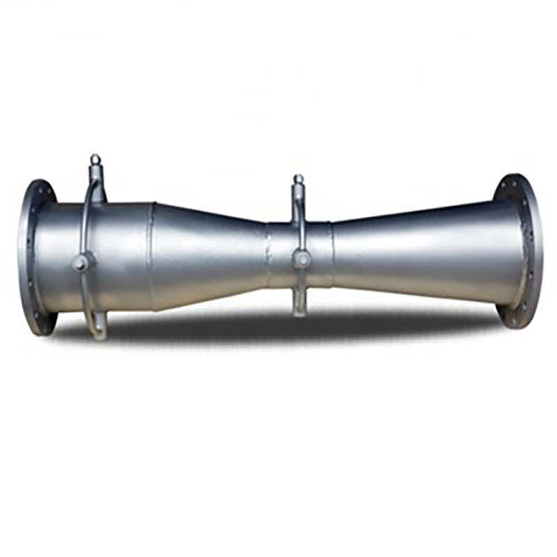
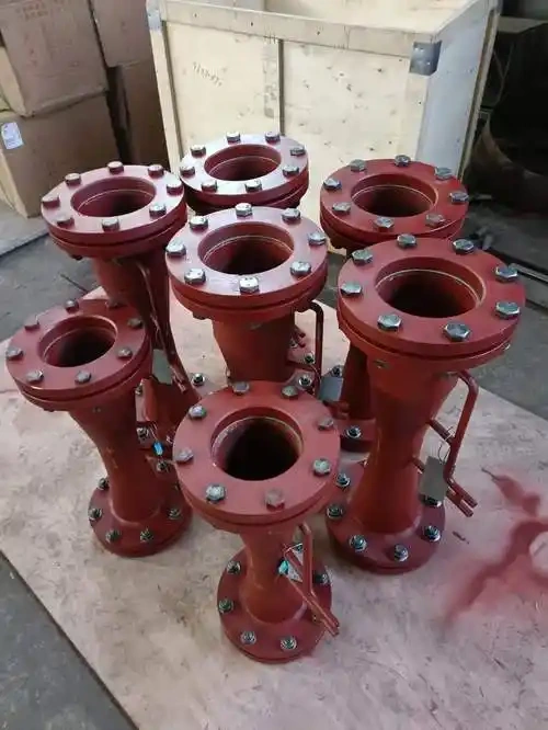
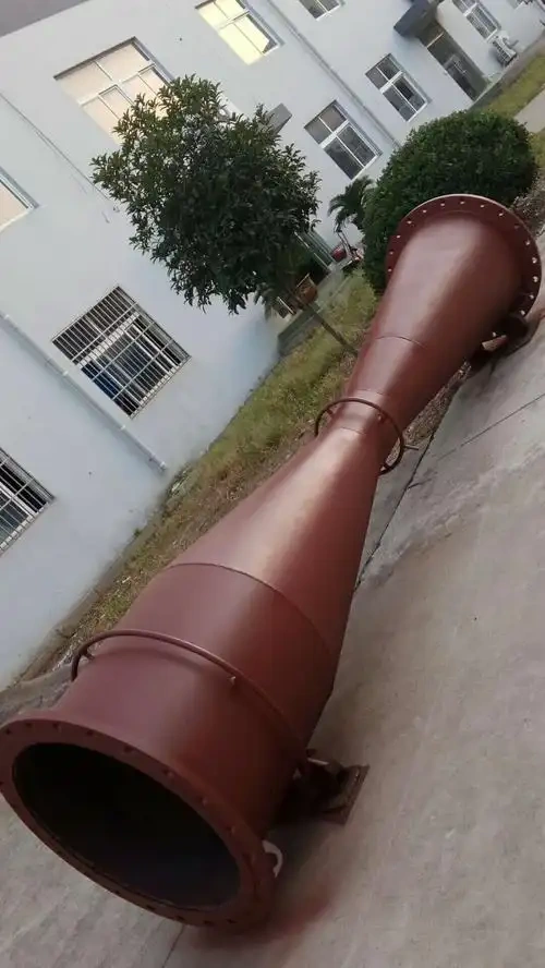
Inlet section: This section matches the pipe internal diameter and has a smooth bore. It conditions the incoming flow, knocking down swirl and turbulence before the fluid hits the contraction.
Contraction section: The cross-section tapers gradually along the flow path, accelerating the fluid. Pressure drops here because static pressure is turning into kinetic energy.
Throat: The straight, narrowest portion of the Venturi tube. Velocity peaks and pressure bottoms out at this point. Pressure taps installed here pick up the throat pressure.
Expansion Section: The cross-section widens again in the flow direction, slowing the fluid back down. Much of the kinetic energy converts back to static pressure, which is why overall pressure loss stays low.
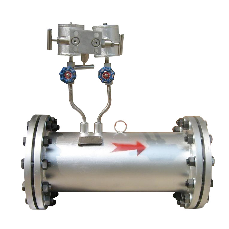
Pressure Tapping Device: Taps in the inlet and at the throat run to a differential pressure transducer. The pressure difference between these two points is the basis for calculating flow rate.
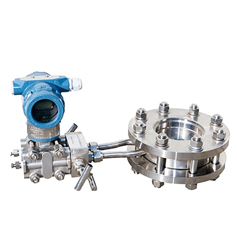
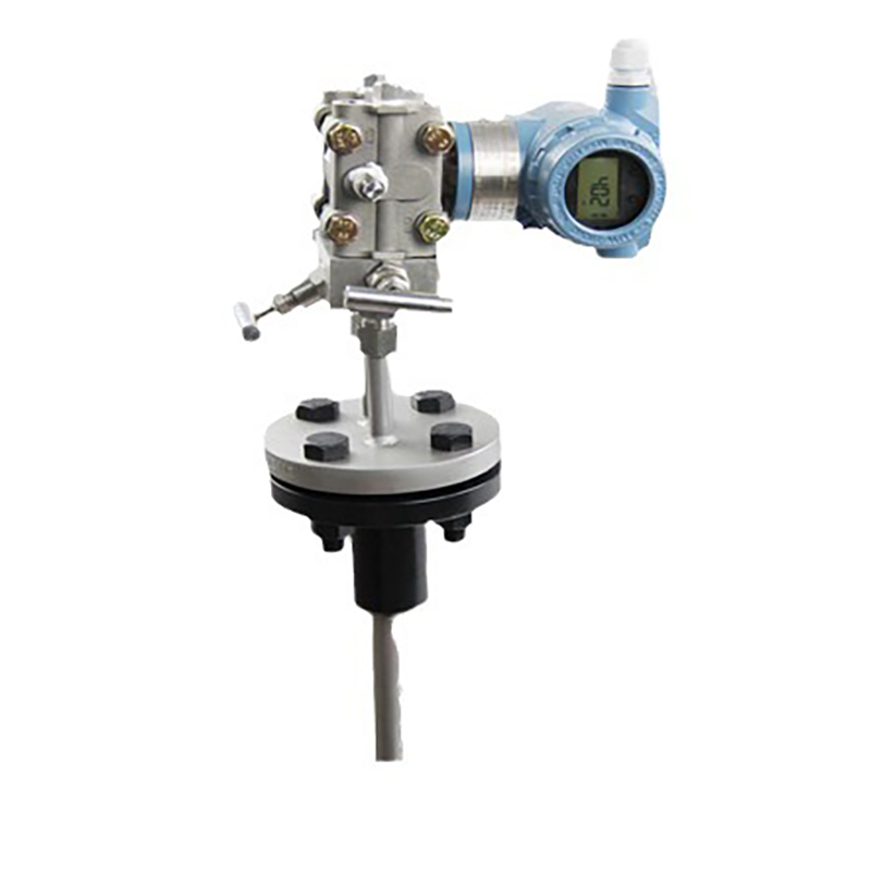
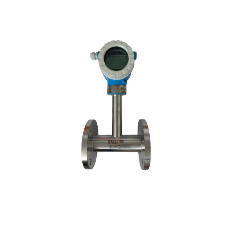
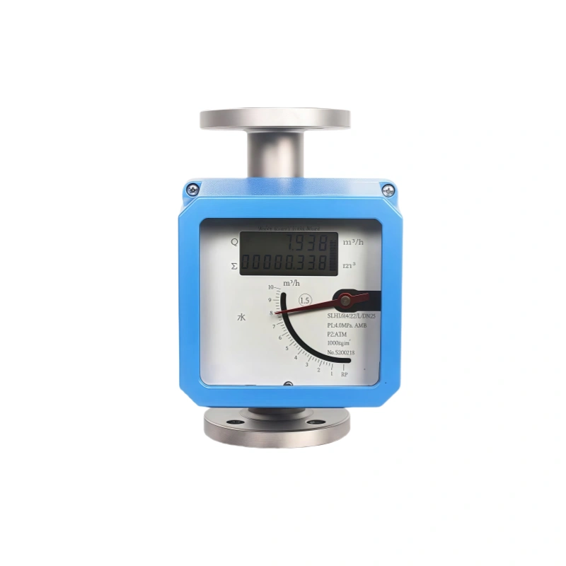
Advantages and Disadvantages of the Venturi Flow Meter
Advantages
1. Low measurement pressure loss: Because the passage narrows and then opens back up, it doesn’t bleed off as much pressure as an orifice plate. That saves energy across the system and lets the meter keep running non-stop for long periods.
2. Wide measurement range: It handles liquids, gases and steam alike. Readings hold up well whether the velocity is high or low, so it fits a broad mix of applications.
3. Good wear resistance: There are no sharp edges inside to get chewed up. When the fluid carries grit or small particles, the internals wear down a lot slower.
4. High measurement accuracy: The throttling principle behind it is tried and tested. Once calibrated, the meter gives you solid, repeatable numbers that stay on the money as long as the process conditions don’t swing around.
5. Suitable for large-diameter applications: Big bore sizes are readily available, making these meters a go-to choice for water mains, drainage networks, district heating lines and large industrial pipe runs.
6. Low operational and maintenance requirements: Nothing inside moves, so there’s not much that can break. You won’t find yourself taking it apart for repairs very often.
7. Suitable for high-temperature and high-pressure conditions: The structure is strong and can be fabricated from various materials, allowing it to survive the extreme temperatures and pressures found in heavy-duty process lines.
8. Less stringent requirements for upstream and downstream straight pipe sections than some flowmeters: Compared with an orifice plate, it needs shorter straight runs upstream and downstream. That is a real advantage when available pipe space on site is limited.
Disadvantages
1. High requirements for pipe length: You need plenty of straight pipe upstream and downstream, which chews up installation space. Fitting one into a cramped area can be a real headache.
2. Susceptible to contaminated media: If the fluid carries solid particles or grit, the constriction and throat tend to foul up and wear down. Once the geometry shifts, accuracy takes a hit.
3. Unsuitable for high-viscosity media: Thick fluids don’t play well with this design. High viscosity thickens the boundary layer, throws the flow coefficient out of whack, and drives up measurement error.
4. Limited turndown ratio: The typical turndown is only 4:1 to 10:1. Performance drops off at low flow rates, so applications with wide flow swings aren’t a good match.
5. Pressure loss still occurs: Although pressure loss is relatively low compared to some differential pressure-type orifice devices, an irreversible pressure loss still exists, leading to additional energy consumption under high-pressure conditions.
6. Inconvenient maintenance and repair: As these are integrated in-line devices, the internal throat cannot be removed and inspected whilst the system is in operation; in the event of wear or blockage, the pipeline must be shut down and the device removed for repair.
Applications
1. Petrochemical Industry
Venturi flowmeters are commonly used to measure the flow of liquids, gases and vapours within pipelines. They are suited to continuous measurement in process pipelines and can be used for flow monitoring at the inlets and outlets of feedstock transfer lines and reaction units.
They can withstand relatively high operating pressures and are reasonably adaptable to media containing small amounts of impurities. When used in conjunction with differential pressure transmitters, they enable real-time flow data acquisition, providing a data basis for process control.
2. District Heating and Thermal Network Sector
These are frequently used for flow measurement of high-temperature hot water and saturated steam, and are widely employed in the main trunk networks of urban centralised heating systems and within the piping systems of heat exchange stations.
Compared to orifice plate flowmeters, they offer lower pressure loss, which can reduce energy consumption in pipeline networks over the long term. They not only monitor the flow of heating media but also support data collection for thermal trade settlement.
3. Water Supply, Drainage and Water Treatment Industry
These meters handle flow measurement in tap-water transmission pipelines and process piping at sewage treatment plants. They work for both clean water and sewage in large-diameter lines.
The Venturi tube’s smooth bore keeps sediment and suspended solids from settling in and causing blockages, giving operators steady readings on inflow, outflow and flow rates through each treatment stage. That consistent data helps the plant crew keep the water treatment process under control.
4. Power Generation Industry
Used to measure boiler feedwater, circulating water and various types of steam flow in thermal and cogeneration power stations; suitable for the high-pressure, high-temperature operating conditions found in power stations.
The equipment offers good vibration resistance and can operate stably over the long term, providing flow parameters for the operational monitoring of boiler and circulating water systems, thereby ensuring the safe operation of the fluid systems associated with power generation units.
5. Metallurgical Industry
Used for flow measurement of blast furnace gas, coke oven gas and various types of process cooling water. As gas media often contain dust and impurities, the Venturi structure is resistant to dust accumulation and blockages.
It meets the flow measurement requirements for complex media and large-diameter pipelines in metallurgical settings, facilitating process adjustments in blast furnaces and coking units.
6. Natural Gas and Gas Transmission Applications
Used for gas flow monitoring in medium- and low-pressure gas pipelines, it is suitable for industrial gas supply pipelines. The smooth flow path results in low pressure loss, reducing energy loss during transmission, enabling gas consumption monitoring and providing data support for the management of gas used in production.
7. Ventilation and HVAC Ductwork
These meters measure airflow inside the ductwork of ventilation systems in large industrial buildings and air-conditioning setups. They come in handy during commissioning, let you see how the system is actually performing, and help with balancing and fine-tuning the airflow.
Calibration of Venturi Flow Meters
The whole point of calibrating a Venturi flow meter is to clean up systematic errors, nail down the actual flow coefficient, and close the gap between theory and what really happens in the pipe. Do it properly and the readings are reliable. Labs and industrial plants run this procedure routinely for standard fluids like water and gases.
The process breaks down into four parts: preparation, testing under operating conditions, data review, and correction. It’s a structured workflow, and each stage has a clear objective.
Before starting, inspect and prep the equipment. Check how the Venturi tube is mounted — the piping should be straight, unobstructed, and properly sealed.Check that the straight upstream and downstream sections are long enough to spec; if they aren’t, flow disturbances will creep in and ruin accuracy.
After that, flush and clean the pressure lines and sensing devices, and make sure all air bubbles are vented from the tubing. Trapped air is enough to throw differential pressure readings off, so purging it is essential.
At the same time, whilst the pipeline is at rest, the zero point must be adjusted and the reference values calibrated. Once equipment commissioning is complete, the fluid system is started up, and stable pressure conditions are maintained within the pipeline.
The formal calibration employs a multi-point variable-flow measurement method, with the flow rate reduced in stages from the maximum rated flow rate, selecting 5 to 8 stable operating points at regular intervals.
Open the valve in small increments. Once the flow and pressure settle down, log the pressure drop across the meter along with the fluid temperature and pressure, then work out the actual flow rate using a standard reference method.
During testing, keep pipeline vibrations and sudden flow changes to a minimum. Steady conditions mean cleaner data and less scatter.
Once all the data is in, calculate the actual flow coefficient for each test point. Throw out any obvious outliers, average what’s left, and check whether the coefficients are stable and linear.
If the deviations go beyond the allowed limits, adjust the equipment parameters and calculation formulas, and put together a calibration curve of differential pressure versus flow rate.
Once calibration is done, run an overall accuracy check. If the results check out, the instrument is good to go. Setting up a regular recalibration schedule will keep the Venturi meter accurate over the long haul.
Venturi Flow Meter Installation Guide
1. Pre-installation Preparation:
Before you start, double-check that the meter’s nominal diameter and rated conditions line up with the pipeline. Inspect the body for any dents, warping, or shipping damage.
If it’s a new line, blow it out thoroughly first — welding slag and construction debris have a habit of getting stuck in the throat or scoring the internal surfaces.
2. Body Installation Specifications:
Mount the meter with the flow arrow pointing the right way; putting it in backwards will throw the readings off completely. Make sure the meter sits dead-centre and square with the pipe run.
When you’re making up the flanges, pick gaskets that fit properly and keep them from sticking into the bore — even a slight protrusion will disturb the flow profile. Tighten the bolts in a criss-cross pattern so the load is even.
Don’t let the meter carry any pipe stress or weight; on larger sizes, put in extra pipe supports so the body doesn’t sag or distort, which would wreck the calibration.
3. Straight Pipe Section Requirements:
Sufficient upstream and downstream straight pipe sections must be ensured; under standard operating conditions, the upstream section must be ≥5–10D and the downstream section ≥3–5D.
Where flow-disrupting components such as elbows or valves are present upstream, the straight pipe section must be extended or a flow straightener installed. Control valves must be installed downstream of the flowmeter; installation upstream is prohibited.
4. Installation of Pressure Taps and Pressure-Taking Tubes:
Select the orientation of the pressure taps according to the medium: for liquids, use the lower half of the pipe; for gases, the upper half; and for steam, the horizontal side. Any associated condensate traps must be installed at the same level.
Pressure run pipes must be of appropriate diameter, with a short route and symmetrical positive and negative lines. The installation gradient must be no less than 1:10; an air vent valve must be fitted at the highest point and a drain valve at the lowest point to prevent air pockets and dead zones where liquid accumulates.
5. Commissioning and Protection:
Position the transmitter appropriately according to the operating conditions of the medium; provide trace heating and insulation for steam and media prone to condensation.
After installation, check for leaks and commission the system in strict accordance with the three-valve manifold operating procedures; ensure that the no-load differential pressure is zero before commissioning. Temperature sensors must be positioned at a distance of no less than 5D from the flowmeter to avoid interfering with the flow field.
Sino-Inst offers a full range of differential pressure flowmetres, including Venturi tubes, V-cones and orifice plates, suitable for a wide variety of complex process conditions.
We provide selection guidance, technical support and accessories such as differential pressure transmitters and three-valve assemblies to ensure the standardised installation and stable, reliable operation of field instruments. Should you require technical consultation for your project, please do not hesitate to contact us for a comprehensive solution.