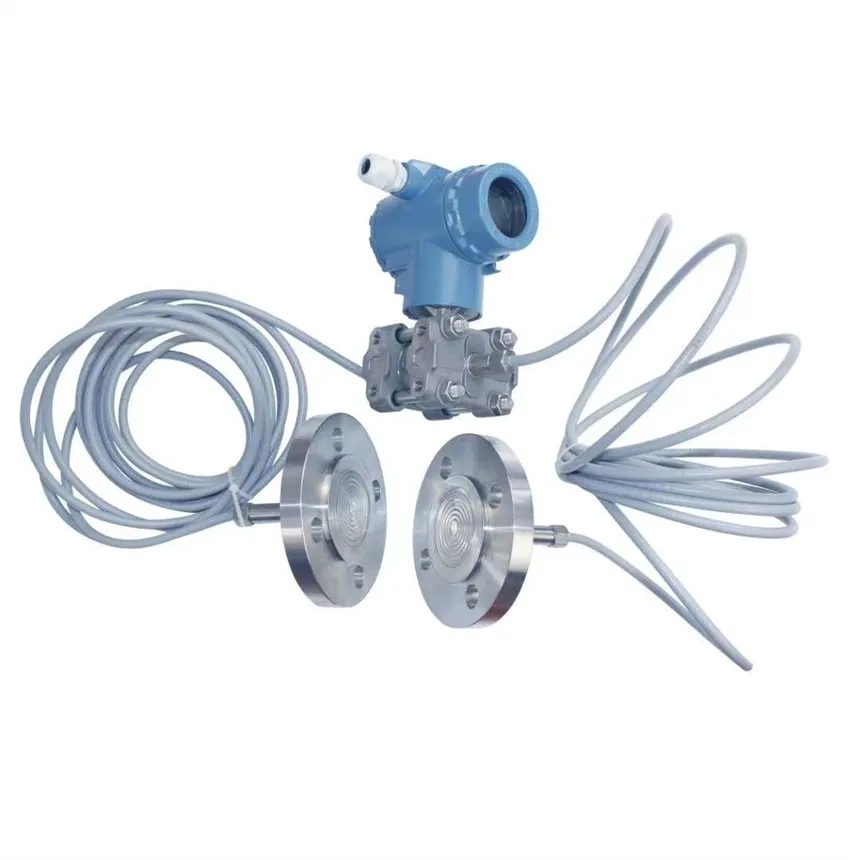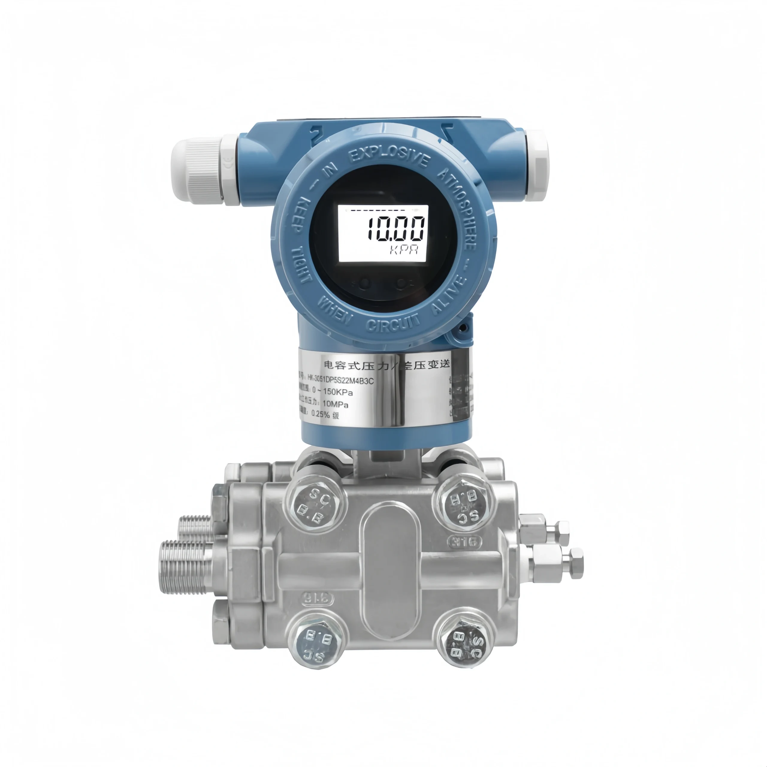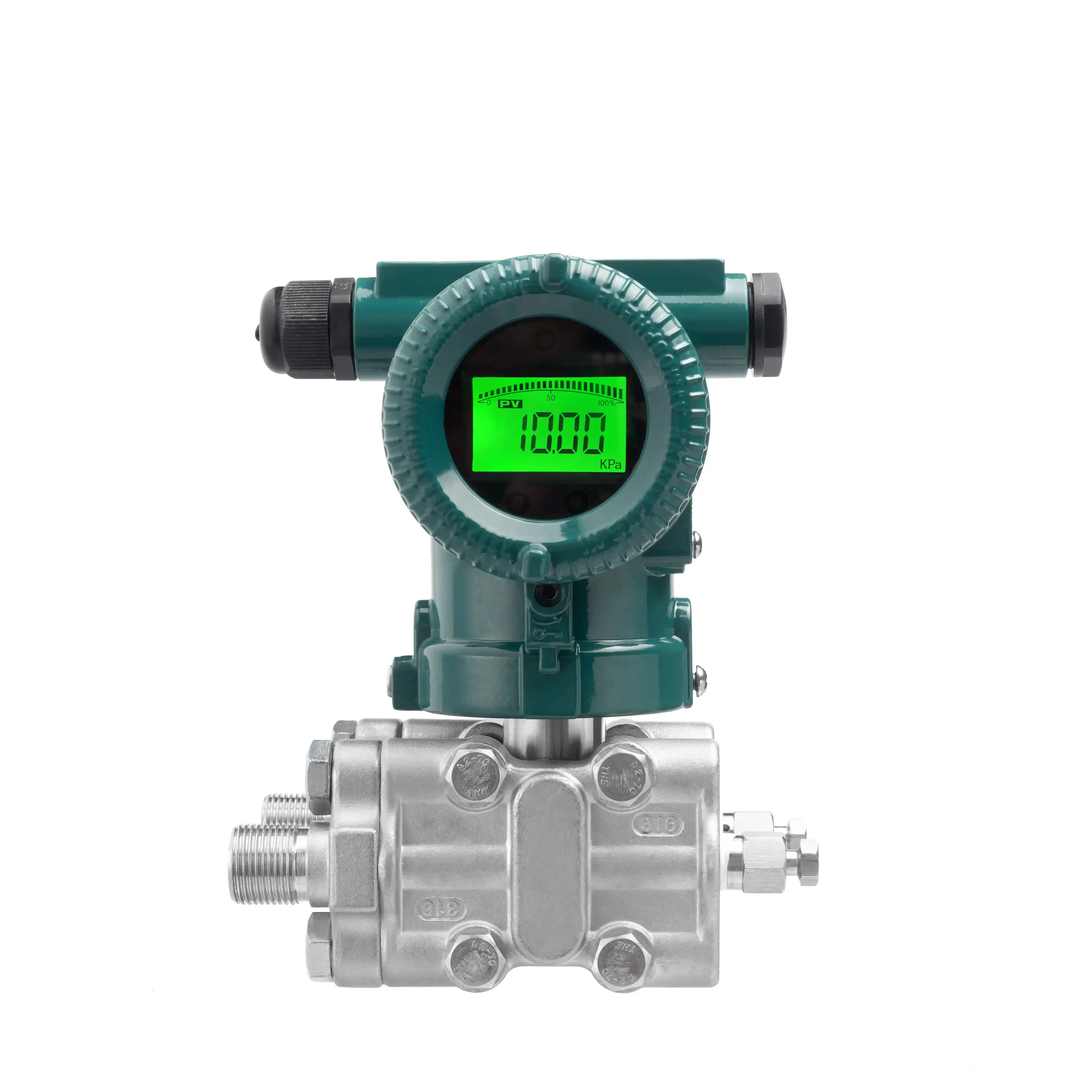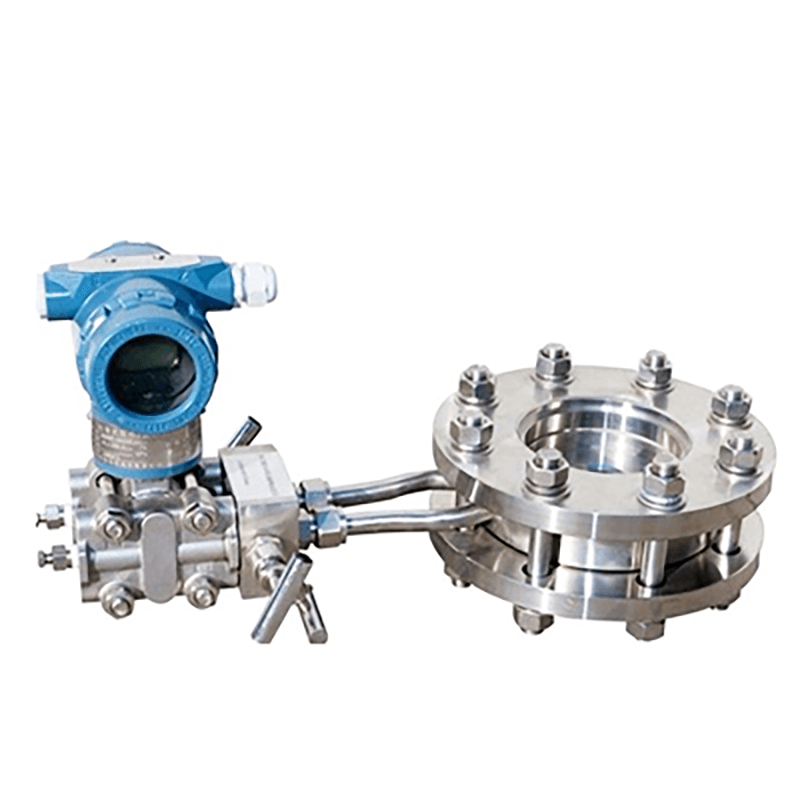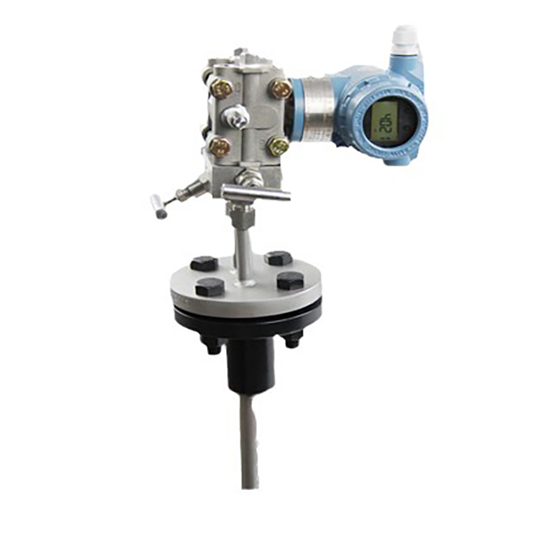
In differential pressure detection systems—such as those for flow and level measurement—the 3-valve manifold controls medium flow and provides pressure equalization.
Proper operation of the 3-valve manifold keeps the transmitter’s sensing elements from getting damaged, cuts down on operational and maintenance risks, and is what makes the differential pressure measurement system reliable in the long run.
Working Principle of Differential Pressure Transmitters
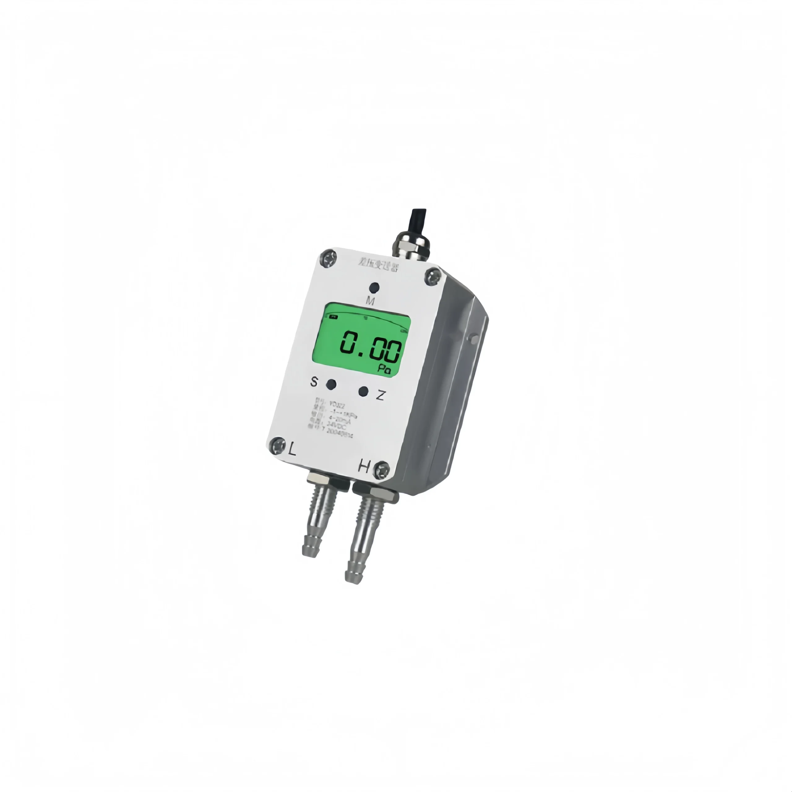
Differential pressure transmitters operate based on the principles of pressure sensing and signal conversion. The two sides are connected to the pressures of the medium being measured, and the resulting pressure difference acts on an isolation diaphragm, which transmits the force to the sensing chip via an internal filling fluid.
The chip generates a weak electrical signal proportional to the magnitude of the pressure difference. After amplification, temperature compensation, and linear correction by the built-in circuitry, this signal is converted into a standard 4–20 mA industrial output signal.
By detecting the pressure difference between two points, the device can indirectly measure process parameters such as level, flow, and pressure. The pressure difference magnitude shows up in the output signal value, and that is what lets operators monitor and control industrial operating conditions with the kind of precision they actually need.
What Is a 3-Valve Manifold for Differential Pressure Flow Meters?
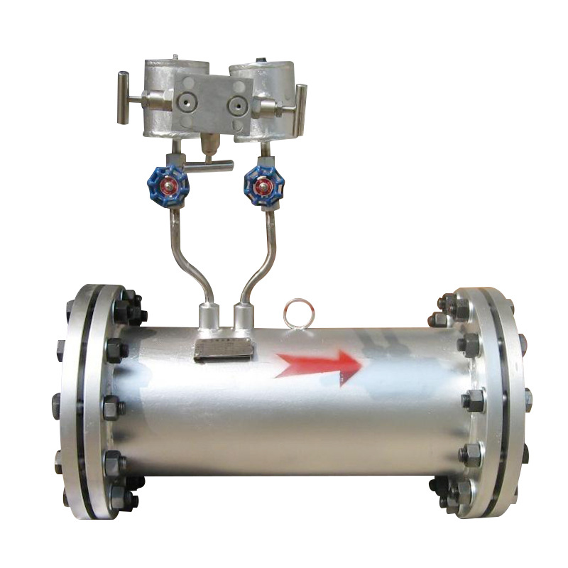
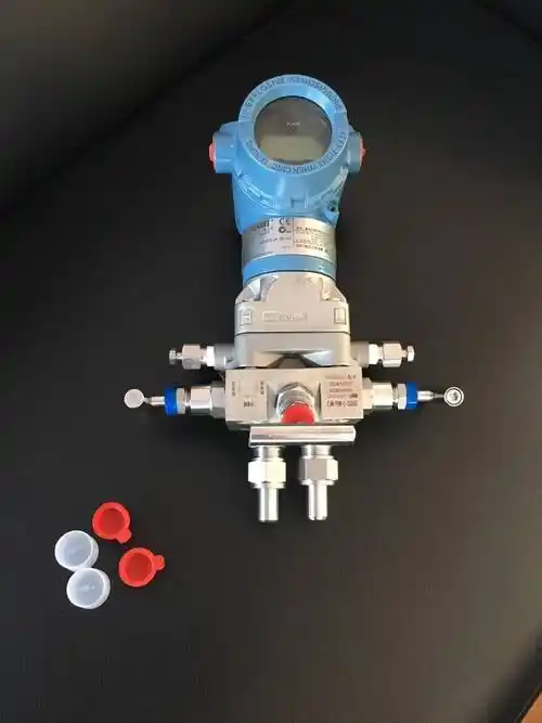
The 3-valve manifold on a differential pressure flow meter—often just called a 3-valve assembly—is a compact valve setup built specifically for differential pressure transmitters.
It has 3 valves in one piece: a high-pressure valve, a low-pressure valve, and a balancing valve. The whole thing mounts right between the pressure taps on the flow meter and the transmitter itself.
During normal operation, the high-pressure and low-pressure valves stay open while the balancing valve stays shut. The pressure drop between upstream and downstream gets fed straight to the transmitter, which then works out the flow rate.
When you need to service the transmitter, calibrate the zero point, or start up or shut down the system, you open the balancing valve first, then close the high- and low-pressure valves in sequence.
That ties the transmitter’s high- and low-pressure sides together, wipes out the differential pressure across it, and keeps the sensor diaphragm from getting wrecked by a one-sided pressure spike.
A 3-valve manifold integrates 3 valves into a single unit. Compared to separately installed individual valves, it reduces the number of pipe connections, lowers the risk of leaks, and simplifies on-site operating procedures. It is widely used in conjunction with various throttling-type differential pressure flowmeters, such as orifice plates, nozzles, and Venturi tubes.
What Is a Differential Pressure Transmitter Valve Assembly?
A differential pressure transmitter valve assembly is essentially a group of dedicated valves mounted directly at the transmitter’s pressure ports. The most common setups are 3-valve and 5-valve manifolds, and they bridge the impulse lines running from the primary element to the differential pressure transmitter.
Under normal operating conditions, the valves cycle through their open and close positions based on what the procedure calls for, letting the differential pressure signal through to the transmitter; during maintenance work, zero checks, or when bringing the unit online or taking it offline, you manipulate the assembly to equalize pressure across the high- and low-pressure sides so the transmitter diaphragm does not get damaged by pressure hitting it from only one direction.
It also gives you a handy point for draining or venting, cuts down on leaks at pipe joints, and generally makes field operation and upkeep less of a headache.
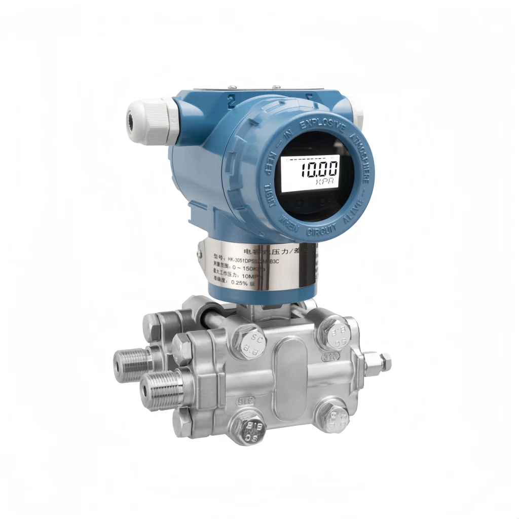
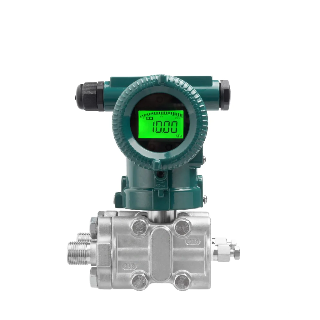
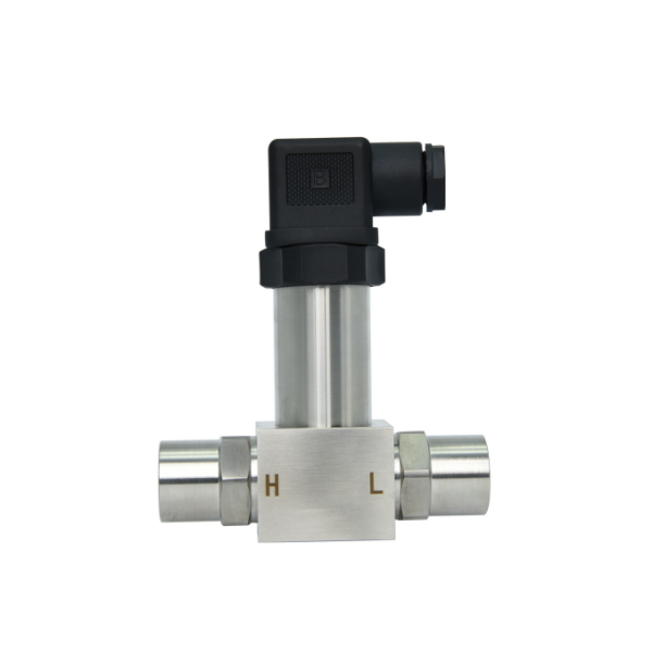
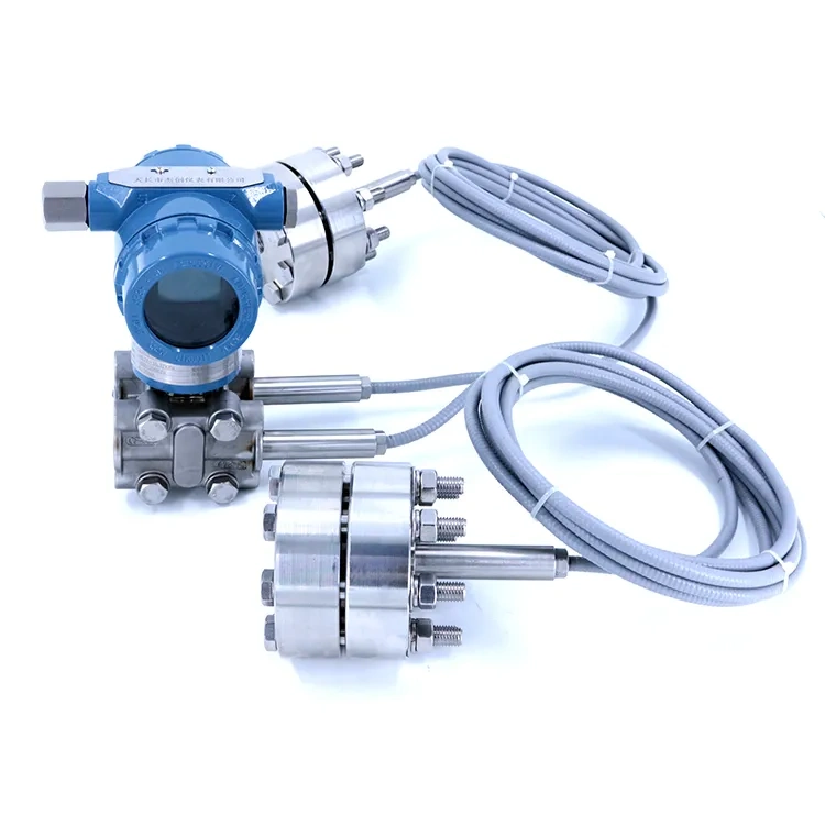
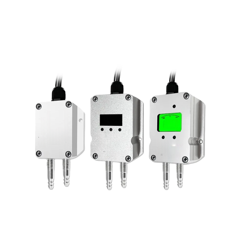
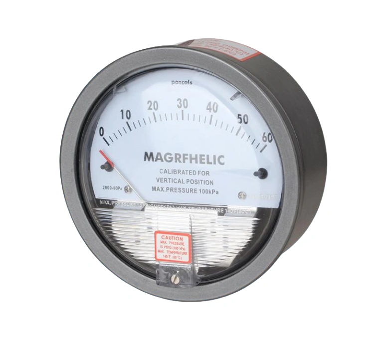
Main Components of a 3-Valve Manifold
1. High-Pressure Shut-Off Valve
The high-pressure shut-off valve controls the flow of the medium into the high-pressure side of the differential pressure transmitter.
Main functions: Isolate the high-pressure process pipeline; to protect the differential pressure transmitter during equipment maintenance; and to facilitate controlled commissioning operations.
2. Low-Pressure Shut-Off Valve
The low-pressure shut-off valve performs functions corresponding to those of the high-pressure shut-off valve on the low-pressure side of the differential pressure transmitter.
Main functions: to shut off the connection to the low-pressure side process piping; to create safe conditions for maintenance work; and to isolate the measuring instrument as required by operating conditions.
3. Balancing Valve
The balancing valve internally connects the high-pressure and low-pressure channels of the manifold.
When the valve opens, pressure on both sides of the differential pressure transmitter levels out. The instrument therefore avoids large pressure differentials during commissioning or zero-point calibration, and the transmitter stays protected from pressure surge damage.
4. Valve Body
The body starts as a single block with flow passages machined directly into it. All 3 valves sit inside this housing, and the standard connection ports are built right in. It serves as the foundation that the rest of the assembly bolts to.
5. Valve Plug, Valve Stem, and Sealing Assembly
This group is made up of the valve stem, plug, packing, and sealing gaskets. Turning the stem drives the plug to open or close the flow path. The sealing assembly keeps the process fluid from escaping and ensures the manifold can hold pressure without leaking.
6. Pipeline Connection Interfaces
These are the ports that hook up to the transmitter and the process pressure tapping lines. They usually come with standard threaded or flanged connections so you get a solid, reliable hookup between the 3-valve manifold, the differential pressure transmitter, and the field pressure tapping lines.
How does a 3-valve manifold work?
Principle of Operation Under Normal Measurement Conditions:
When the system is running normally, both the high- and low-pressure shut-off valves are wide open and the balancing valve stays shut. Process pressure enters the high- and low-pressure sides of the transmitter through separate lines.
The transmitter reads the pressure difference between the two sides and outputs a measurement signal. Because the balancing valve stays closed, the two chambers remain isolated, so no fluid bleeds across from one side to the other. That separation keeps the reading accurate and prevents cross-contamination.
Instrument Balancing and Calibration Principle:
For zero-point calibration or during commissioning, start by shutting the high- and low-pressure shut-off valves to block off the process pressure source, then open the balancing valve.
That ties the two transmitter chambers together, equalizes the pressure on both sides, and brings the differential pressure down to zero. Doing so gives you the baseline conditions you need for a proper calibration and makes sure the instrument is zeroed accurately.
Principle of Protection During Equipment Commissioning:
Start by opening the balancing valve so the high- and low-pressure chambers are tied together. Then crack open the shut-off valves on both sides gradually to let process pressure in, letting pressure build up on both ends at roughly the same rate.
That way you do not get a hard hit from high pressure on just one side slamming into the instrument diaphragm, and you sidestep damage from a differential pressure overload.
Safety Principle for Shutdown and Maintenance:
When you are taking the equipment out of service for maintenance or pulling the instrument apart, shut the high- and low-pressure shut-off valves first to cut off the process medium, then open the balancing valve.
That equalizes and bleeds off any residual pressure still sitting inside the transmitter, getting rid of the risk from pressure differentials and giving you safe conditions to work on, remove, or reinstall the instrument.
Integrated Sealing and Pressure Control Principle:
The 3-valve manifold is built as one solid piece with clean, separate internal flow paths, and it comes with a full set of sealed valves.
Each valve opens and closes independently and seals up tight, so you can isolate, vent, or balance pressure exactly when and where you need to. That keeps the control system pressure steady and the instrument running safely and reliably over the long haul.
Advantages of Using a 3-Valve Manifold
1. You can zero-calibrate the differential pressure transmitter right where it sits without pulling it out.
Just work the balancing valve along with the high- and low-pressure shut-offs to isolate the process pressure and equalize both sides of the transmitter. That makes field commissioning and routine calibration a lot less hassle.
2. It cuts down on the chance of the process fluid leaking out.
Because the piping and valves are machined into a single block, there are far fewer joints between the transmitter and the impulse lines, so there are fewer places for leaks to develop. That is why these manifolds are standard in applications handling flammable, explosive, or toxic media—oil and gas, chemical plants, and similar industries—where you simply cannot afford leaks.
3. It protects the transmitter’s sensing element.
During startup or shutdown, following the correct valve sequence prevents high pressure from striking the sensor diaphragm from one side only. That avoids permanent damage from one-sided overpressure and gives the transmitter a longer service life.
4. Simplifies piping layout and saves installation space.
The manifold bolts straight onto the differential pressure transmitter body, so you do not have to assemble a string of individual valves in the field. That keeps the piping neat and compact, which is especially handy when you are working in tight instrument bays with barely any room to spare.
5. Reduces on-site construction and maintenance time.
Because the valve assembly ships from the factory as one complete unit, there is far less welding and threading to do during installation. Later, when maintenance is due, you do not have to rip apart the whole impulse line system to get at the transmitter, so downtime and headaches both stay lower.
6. Promotes stable measurement accuracy.
Fewer external connections mean less pressure lag and fewer fluctuations interfering with the signal. The high- and low-pressure paths are shorter, so the differential pressure reaches the transmitter more quickly and smoothly. That keeps your flow and level data solid and reliable.
Common Applications of 3-Valve Manifolds
1. Differential pressure flow measurement circuits.
When you pair a 3-valve manifold with throttling devices—such as orifice plates, nozzles, Venturi tubes, or wedge meters—and a differential pressure transmitter, you get a standard setup for tracking liquid, gas, or steam flow through pipelines. This is the most common place you will actually run into these manifolds.
2. Level measurement in sealed vessels.
Differential pressure transmitters measure liquid level in equipment like storage tanks, reactors, and separators, and the 3-valve manifold lets you zero the transmitter right on site without stopping production or pulling the instrument out.
3. Equipment differential pressure monitoring.
Keeping tabs on the pressure drop across filters, heat exchangers, and pipeline sections lets you spot blockages and catch abnormal operating conditions while the equipment is still online.
4. Oil and gas process flows.
Differential pressure instruments on gathering and transmission pipelines, metering skids, and separator units almost always ship with a 3-valve manifold. These manifolds are rated for flammable and explosive media, and since the valves and ports are machined into a single block, there are far fewer joints where leaks can develop.
5. Measurement systems in chemical production facilities.
In chemical plants, 3-valve manifolds handle differential pressure detection on corrosive and toxic media across reaction units and distillation systems. They allow operators to isolate the instrument and perform online calibration without taking the process offline, which keeps the operation safer overall.
6. Thermal Power and District Heating Systems.
For steam flow in boiler piping and differential pressure level on steam drums, 3-valve manifolds handle high-temperature steam impulse lines without issue. They also make regular instrument calibration and maintenance much easier for the technicians on site.
7. Water Treatment and Water Supply Engineering.
In water supply pipelines and purification equipment tanks, 3-valve manifolds handle flow measurement along with differential pressure and level detection, covering the continuous monitoring needs typical of standard industrial water treatment.
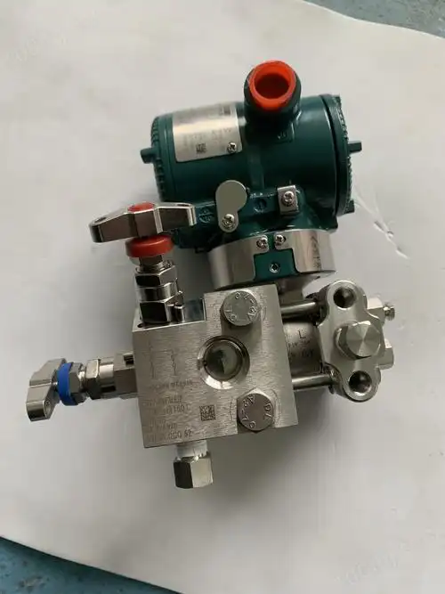
The 3-valve manifold is a staple in differential pressure measurement systems. It is safe, reliable, easy to install, and works with a wide range of equipment, which is why it remains a solid choice for process measurement and control across so many industries.
Sino-Inst carries 3-valve manifolds in various materials, pressure ratings, and connection sizes. We also supply the full range of industrial measurement equipment you need—differential pressure transmitters, orifice plates, level instruments, and more—so you can put together a complete flow, level, or differential pressure monitoring system from one source.
We have deep experience in selecting equipment for specific applications, and we can tailor solutions for just about any field environment, whether you need standard products or custom development.
If you have questions about product selection, technical specifications, or project integration, just reach out to our technical team. We will get you a practical, efficient solution that keeps your measurement system running safely and reliably over the long term.