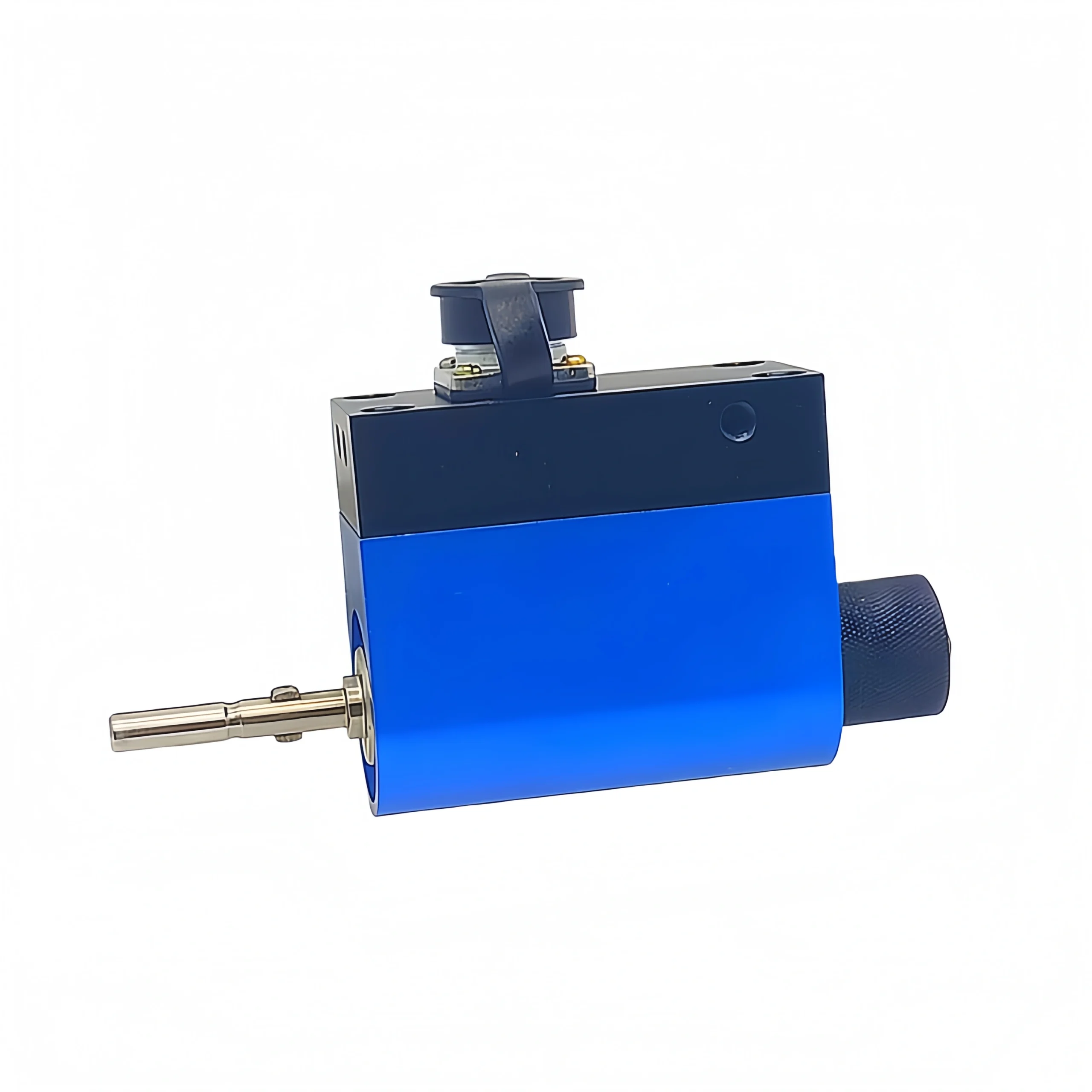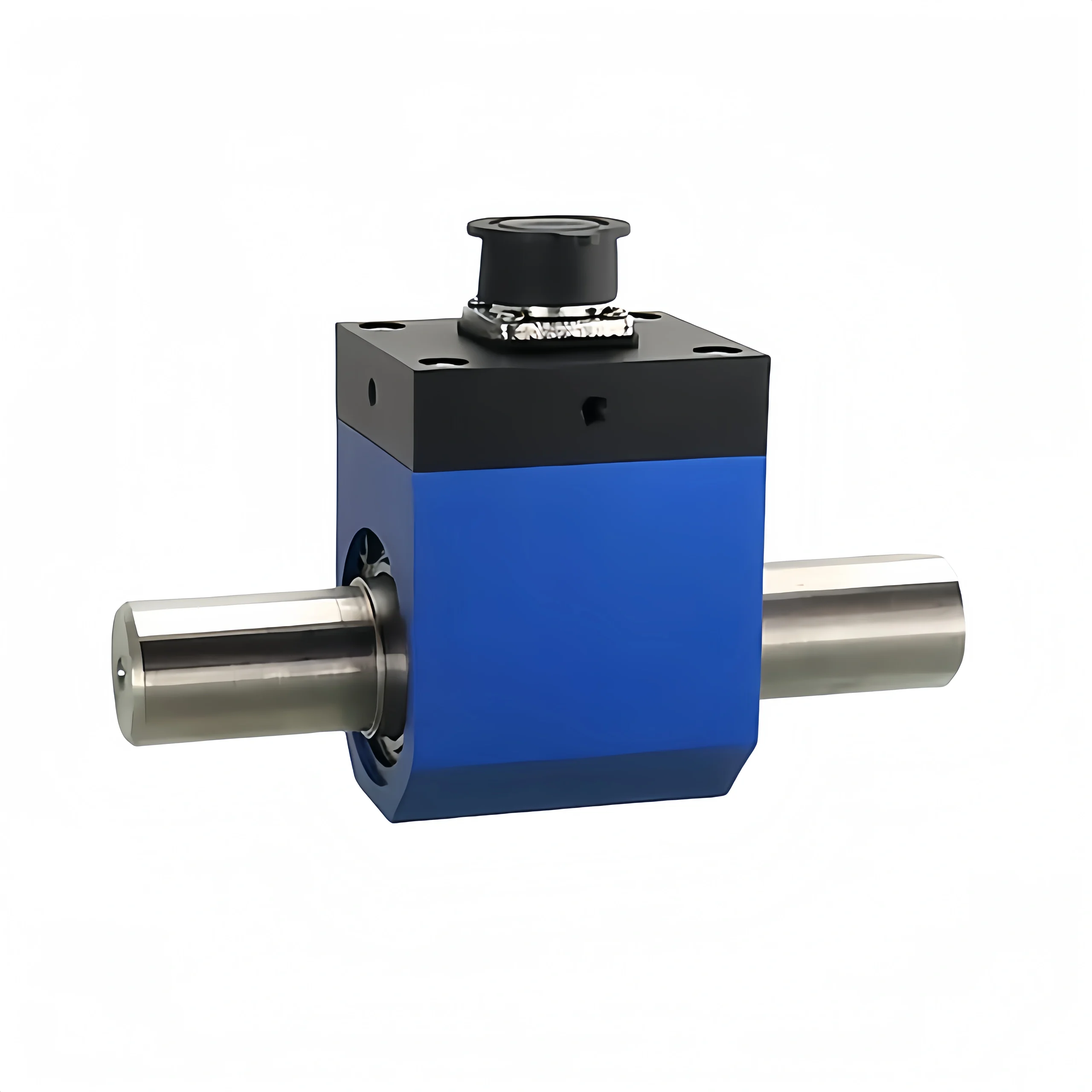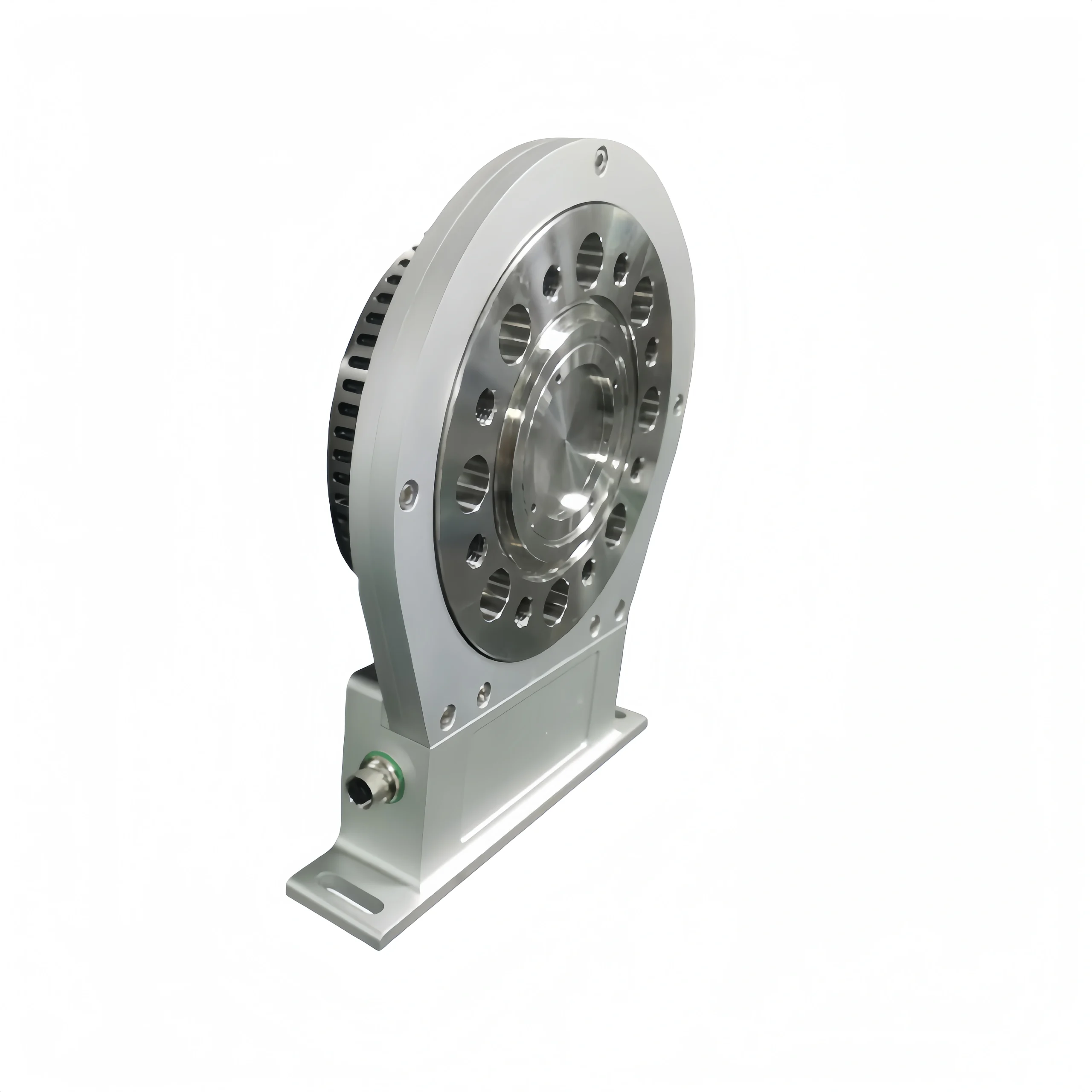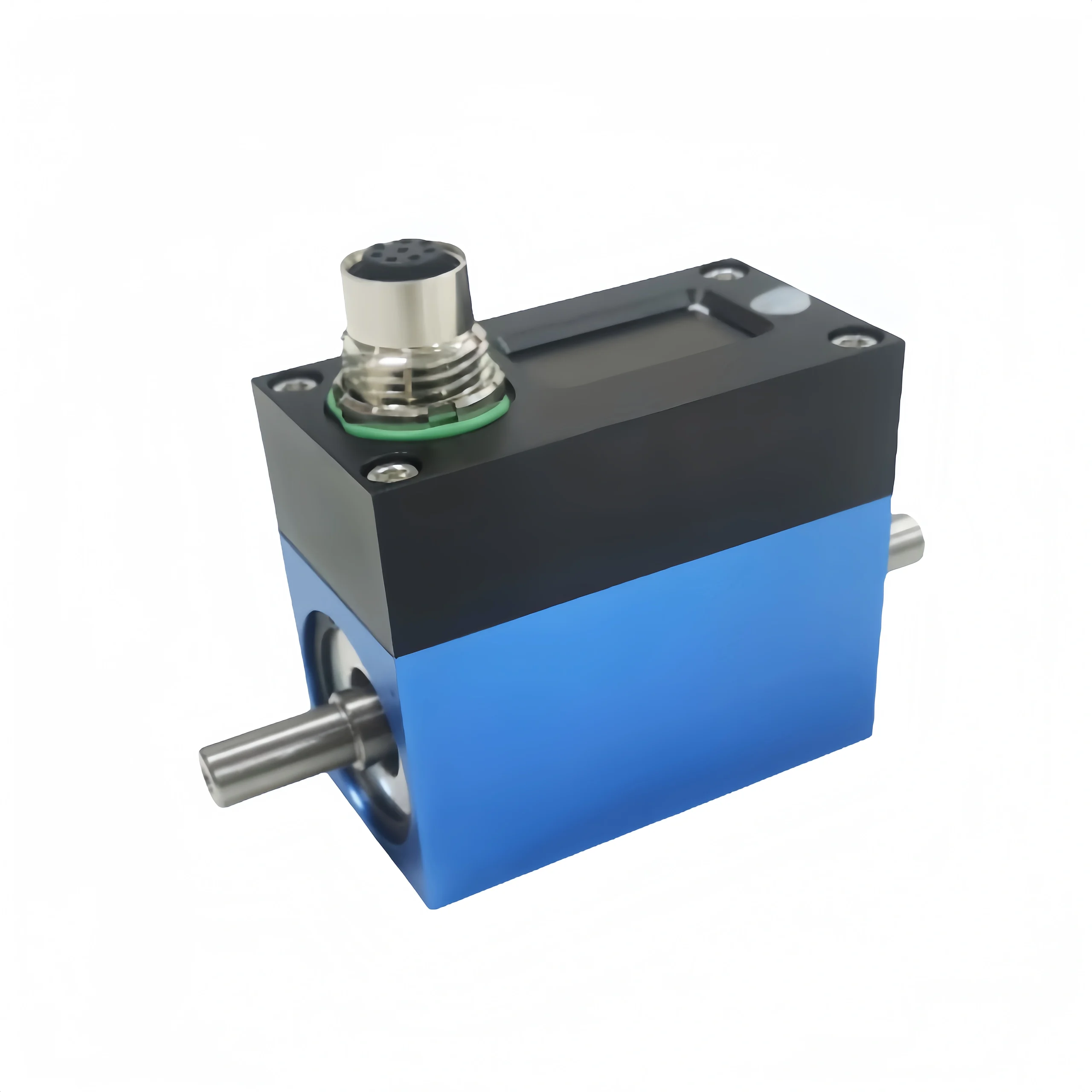
Torque sensors are crucial measuring components in modern industry. They play an irreplaceable role in power transmission, mechanical control, and automated production. Torque sensors can accurately measure the magnitude and direction of torque in real time. Provide reliable data support for equipment operating status monitoring and fault warning. This article provides a selection guide. To help readers choose the most suitable torque sensor.
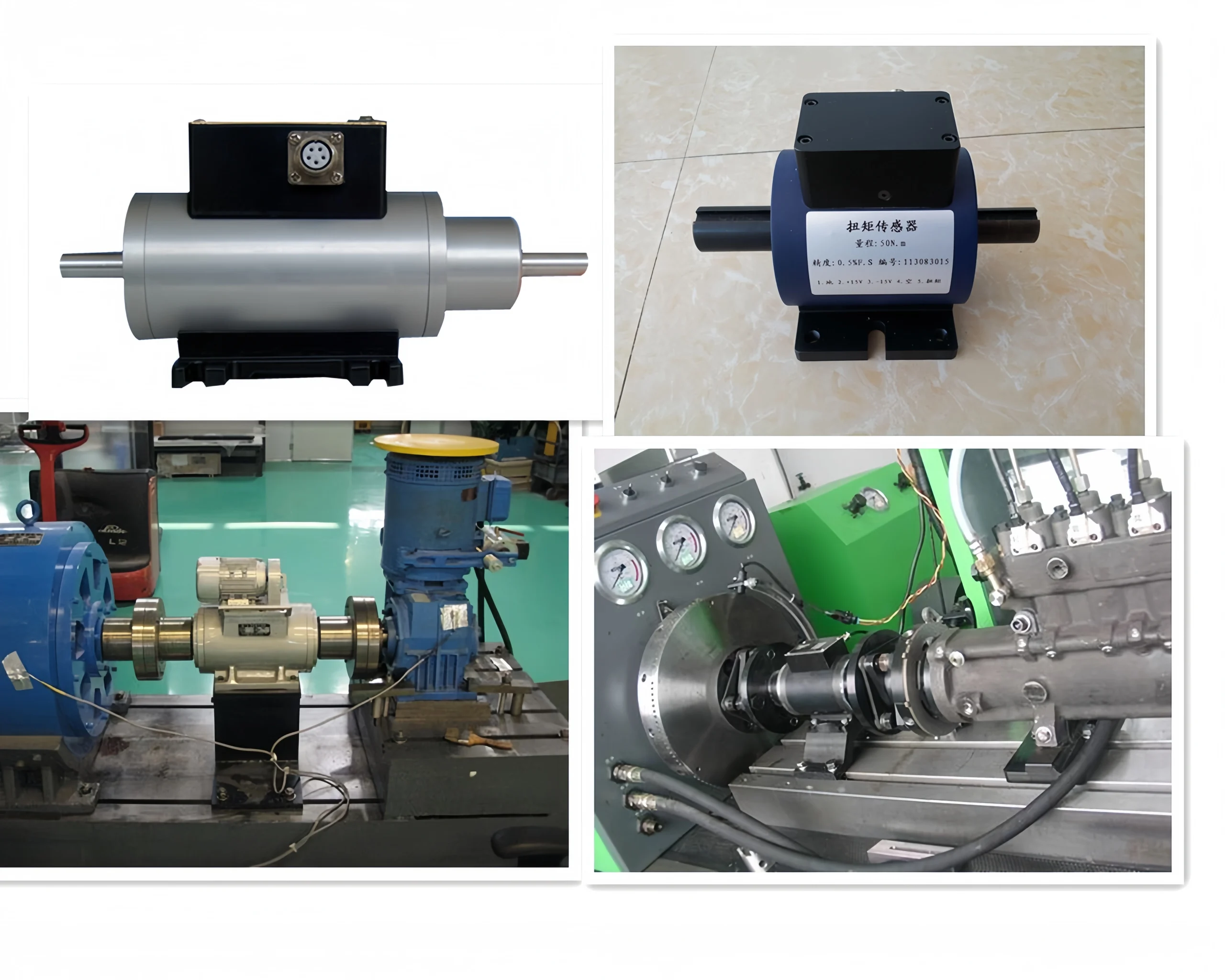
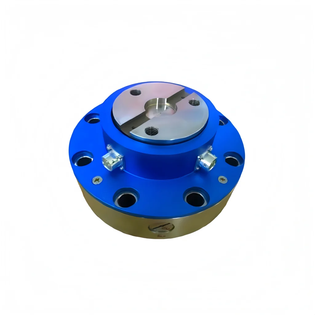
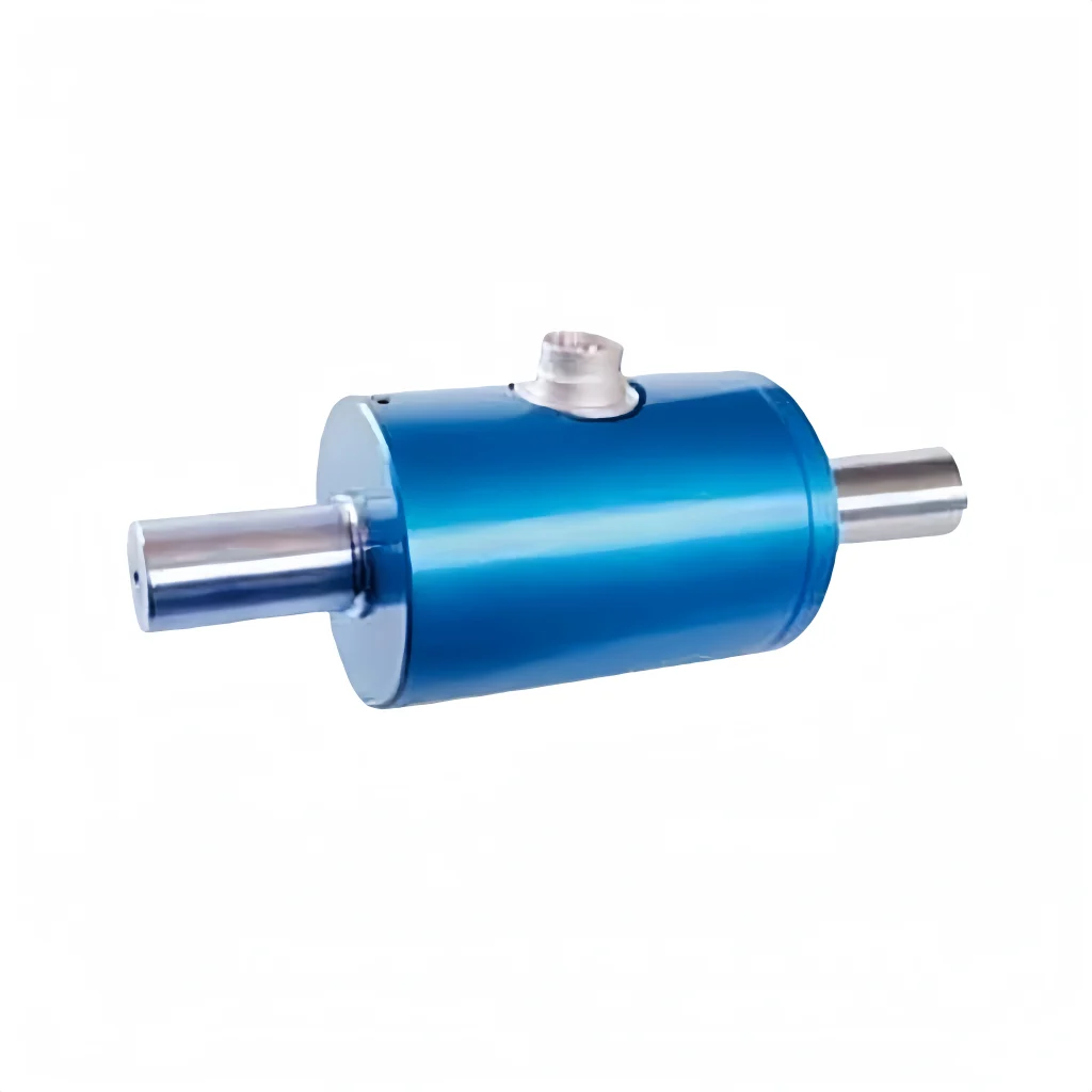
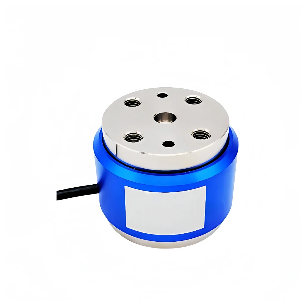
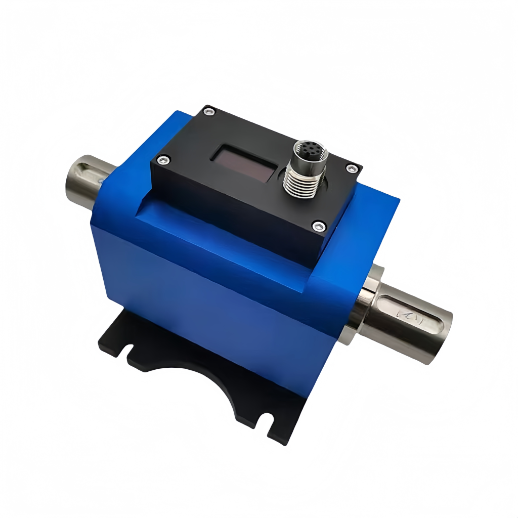
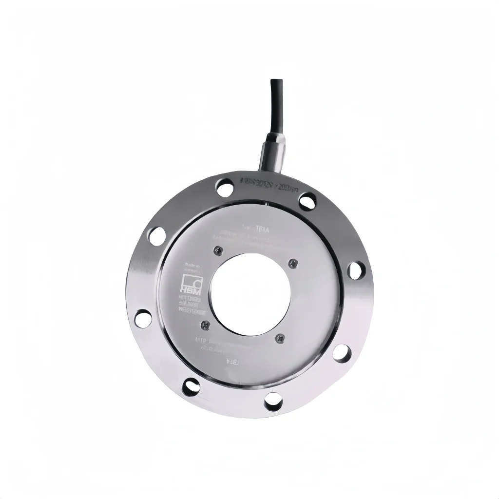
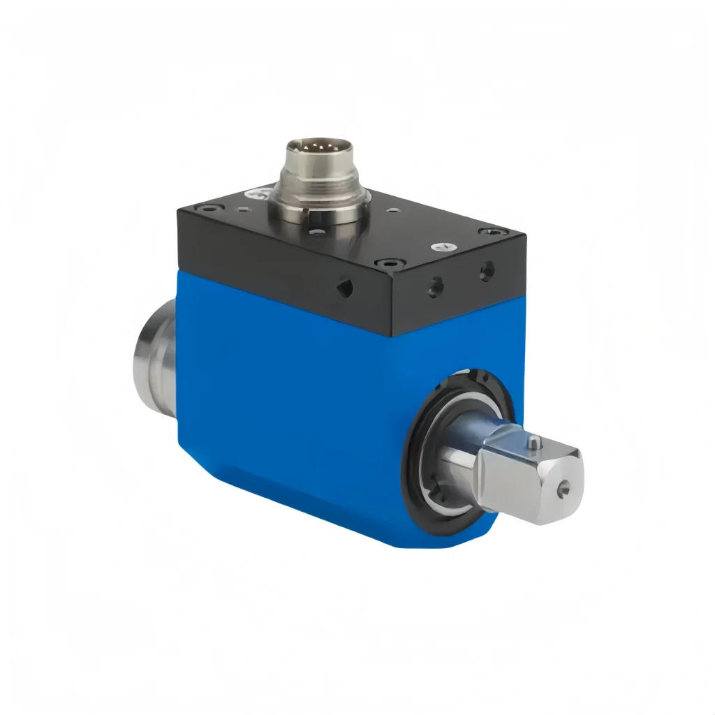
A torque sensor detects torsional torque on various rotating or non-rotating mechanical components. A torque sensor converts the physical change in torque into a precise electrical signal. Torque sensors can be used in the manufacture of viscometers and electric (pneumatic, hydraulic) torque levers. They offer high accuracy, fast frequency response, excellent reliability, and long life.
Torque sensors primarily infer torque by measuring the torsional deformation of a shaft. Their basic principle is to sense the amount of shaft torsional torque. using strain gauges, capacitors, optical fibers, and other technologies. The operating principles of torque sensors depend on the application requirements.
When selecting a torque sensor, it’s important to understand the sensor’s measurement principle. Ensure compatibility with the application.
Torque Sensor Features:
- Can measure both static and dynamic torque.
- High detection accuracy and stability.
- Strong anti-interference performance.
- Small size, light weight, and a variety of mounting configurations make it easy to install and use.
- Continuously measures forward and reverse torque without repeated zeroing.
- No wearing parts. such as conductive rings, allowing for long-term operation at high speeds
- The sensor outputs a high-level frequency signal. The signal can be directly sent to a computer for processing.
- The measuring elastomer is strong. And it can withstand overloads up to 200% FS.
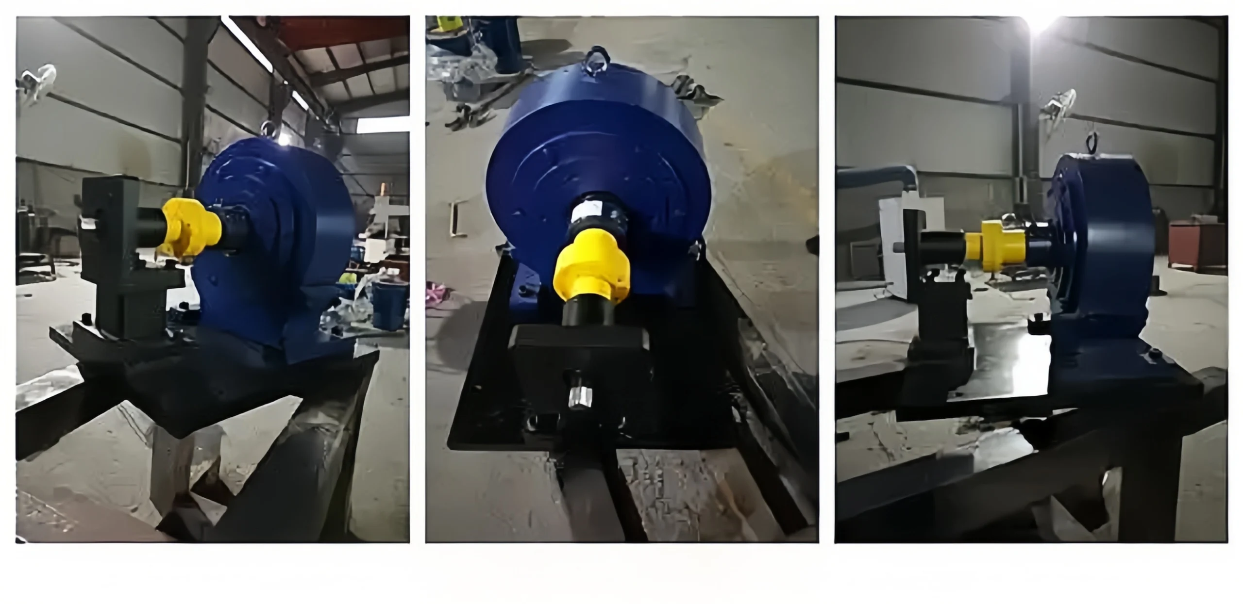
I. Classification by Measurement Principle
Strain Gauge Torque Sensors
These sensors rely on the deformation of an elastic shaft under torsional stress. A strain gauge bridge is attached to capture micro-deformation signals. They are subdivided into solid-shaft and hollow-shaft structures and include both static torque and dynamic rotational torque models. As the most widely used type in industry, they are suitable for various operating conditions at both high and low rotational speeds.
Magnetoelectric Torque Sensors
These detect shaft torsional displacement by measuring changes in magnetic flux. They employ non-contact measurement and do not require slip rings. They are classified into magnetic grating and magnetoresistive types, are resistant to dust and oil contamination, and are suitable for high-speed rotation and harsh, lubrication-free environments.
Capacitive Torque Sensors
Torsional deformation alters the distance between the electrodes; torque is calculated based on the resulting change in capacitance. These sensors are compact and feature fast response times, making them ideal for use in micro-motors and applications requiring precise measurement of minute torque values.
Optoelectronic Torque Sensors
Grating discs are mounted at both ends of the shaft; torsion creates a phase difference, and an optical probe captures pulse signals to calculate torque. These sensors offer extremely high measurement accuracy, have no mechanical contact, and are suitable for precision calibration in laboratories and high-speed servo equipment.
Piezoelectric Torque Sensors
Piezoelectric crystals generate electrical signals when subjected to torsional stress. They feature outstanding high-frequency response characteristics but are only suitable for transient and impact torque detection; they cannot be used for long-term measurement of static, constant torque.
II. Classification by the Motion State of the Measured Shaft
Static Torque Sensors
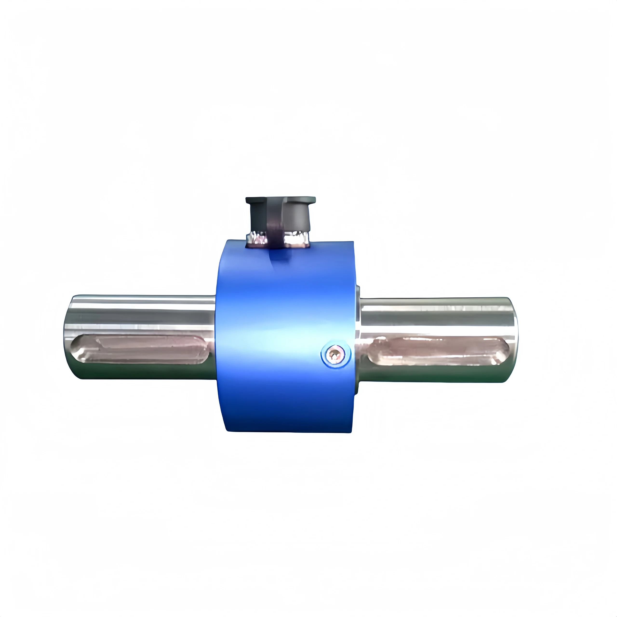
These sensors measure torque only when the shaft is stationary or undergoing slow starts and stops without continuous rotation. They feature a simplified structure and do not require signal transmission slip rings or wireless modules. Their measurement range covers both minute and large torque values, and they are commonly used for valve tightening, bolt fastening, and tooling clamping tests.
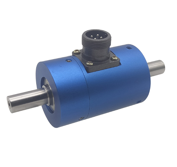
Dynamic Rotating Torque Sensors
Used in applications where the shaft operates continuously at high speeds; these are subdivided into two categories:
(1) Contact slip ring type: Strain signals are transmitted via carbon brush slip rings. These sensors are low-cost but are not suitable for ultra-high speeds and have a limited service life due to wear;
(2) Non-contact wireless telemetry type: Equipped with a built-in RF wireless transmission coil, these sensors have no mechanical wear and support long-term operation at speeds exceeding ten thousand revolutions per minute.
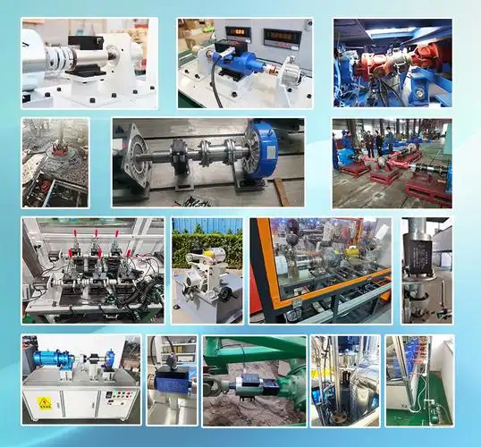
Measurement Requirements
Different application scenarios place varying demands on torque sensors. For example, static torque sensors are more suitable for measuring torque values in static. Dynamic torque sensors are more suitable for these scenarios. Involving rapid rotation and dynamic changes. Therefore, before selecting a torque sensor, you need to clearly understand the factors. such as the torque range, speed, and operating environment to be measured. Ensure that the selected sensor meets your actual needs.
Accuracy Level
Accuracy level is a key indicator of the measurement accuracy of a torque sensor. Generally, higher accuracy levels result in more precise measurements. However, higher-accuracy torque sensors often come with higher prices. Therefore, when selecting a torque sensor. You need to balance your actual needs with your budget. For high-precision measurement applications, a torque sensor with a higher accuracy level can be selected. For practical applications, a torque sensor with a moderate accuracy level can be selected.
Acquisition Frequency
For extremely high acquisition frequency requirements, a slip ring torque sensor is recommended. However, the speed of a slip ring sensor cannot exceed 3000 rpm. Internally, brushes are used for the power supply and signal output. And prolonged rotation will wear the brushes. Compared to non-contact dynamic torque sensors, slip ring torque sensors cannot measure speed. Non-contact torque sensors (power supply and signal) meet most measurement needs.
Sensor Installation Method and Structure
Different types of torque sensors have different installation requirements. For example, magnetoelectric torque sensors require strict alignment during installation. Otherwise, the sensor’s elastic shaft may bend, resulting in additional error.
Sensor Output Signal and Interface
To meet diverse user needs, torque sensors offer a variety of signal outputs. It includes
frequency, voltage, current, and RS232/485.
Frequency Signal: 5kHz to 15 kHz.
Voltage Signal: 0-5V, 0-10V, -5V-5V, -10-10V, and mV/V options available
Current Signal: 4-20mA
The torque sensor’s output signal and interface must be compatible with the measurement system or data acquisition device.
Choosing a Torque Sensor Range
Torque Sensors can be categorized by range:
Micro Range: 0.2Nm to 5Nm
Small to Medium Range: 5Nm to 200Nm
Medium to Large Range: 10Nm to 300kNm
If torque is measured statically, the selected sensor should have a range that matches the maximum load of the device. When measuring dynamic torque (where the power supply cannot control speed), select a torque sensor with a range that is twice the maximum load torque of the device. If you have a converter to control the power supply speed. You can choose a torque sensor with a range that matches the maximum load torque of the device.
Axial Dimensions
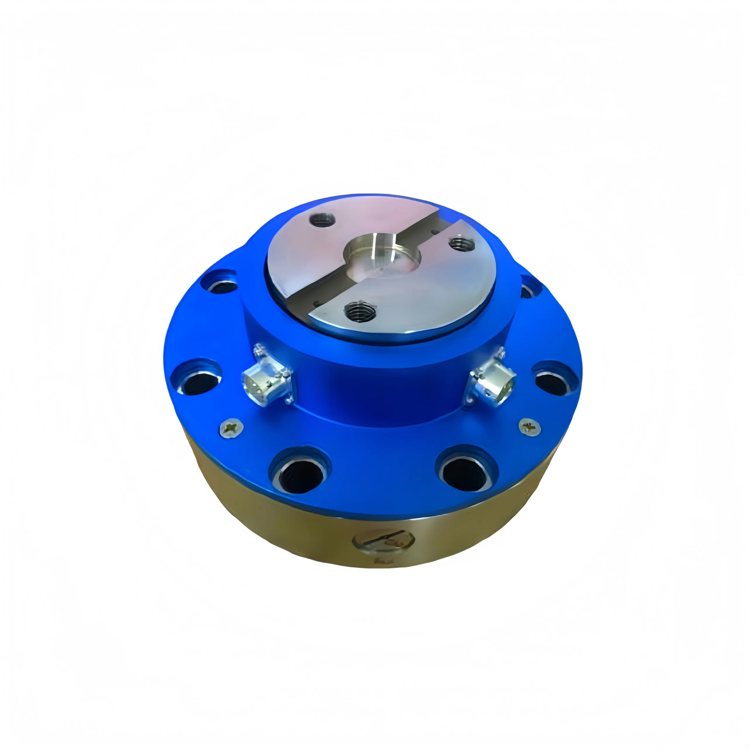
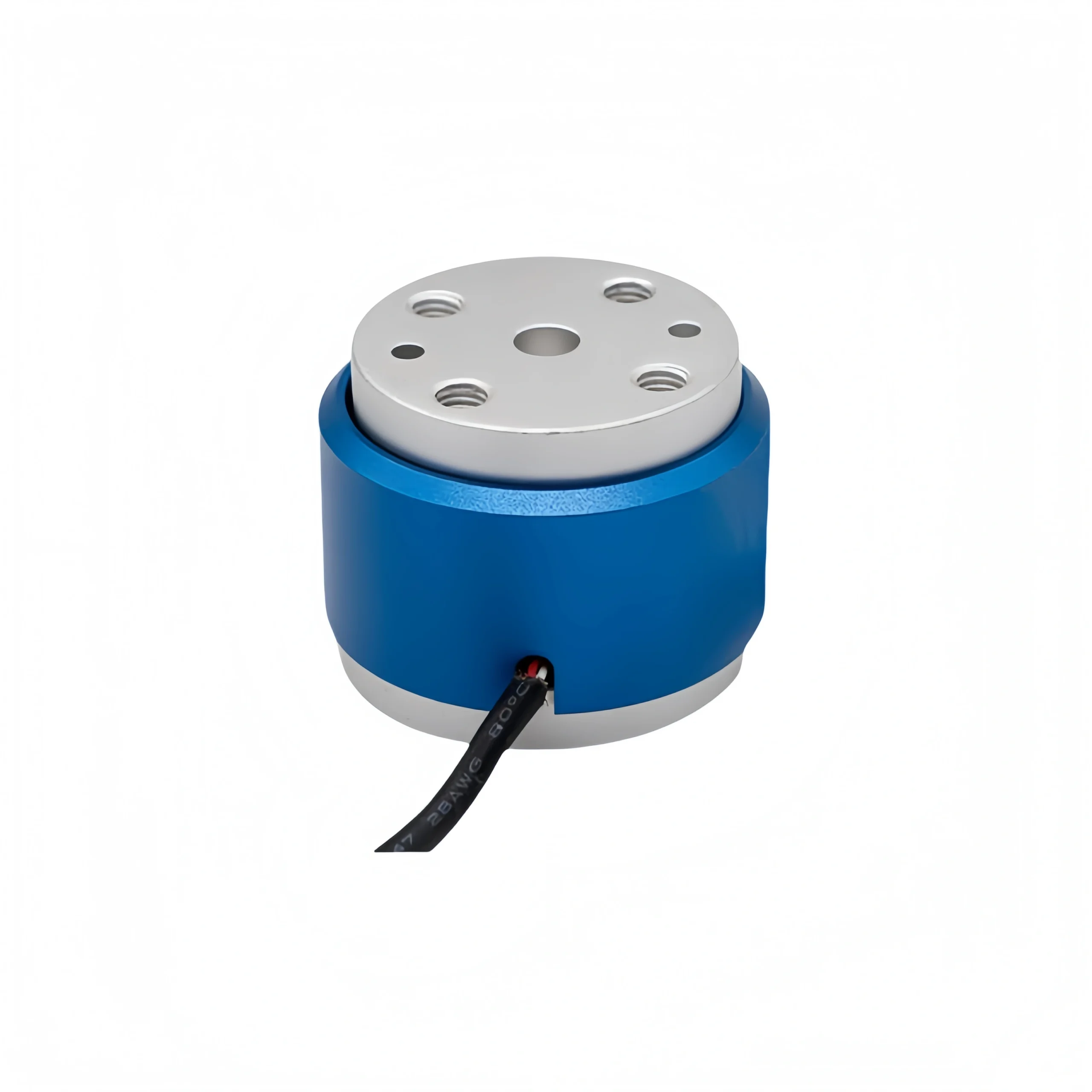
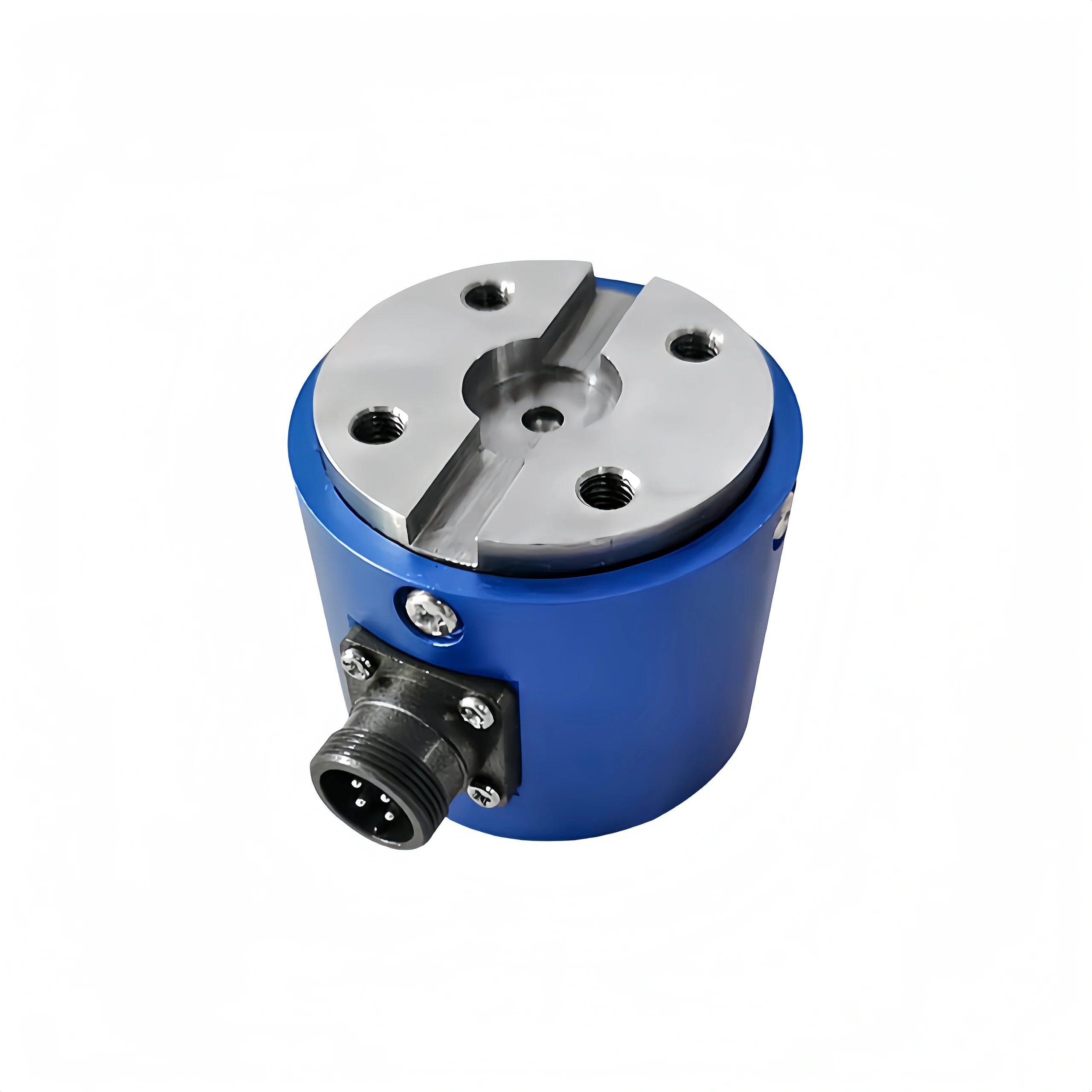
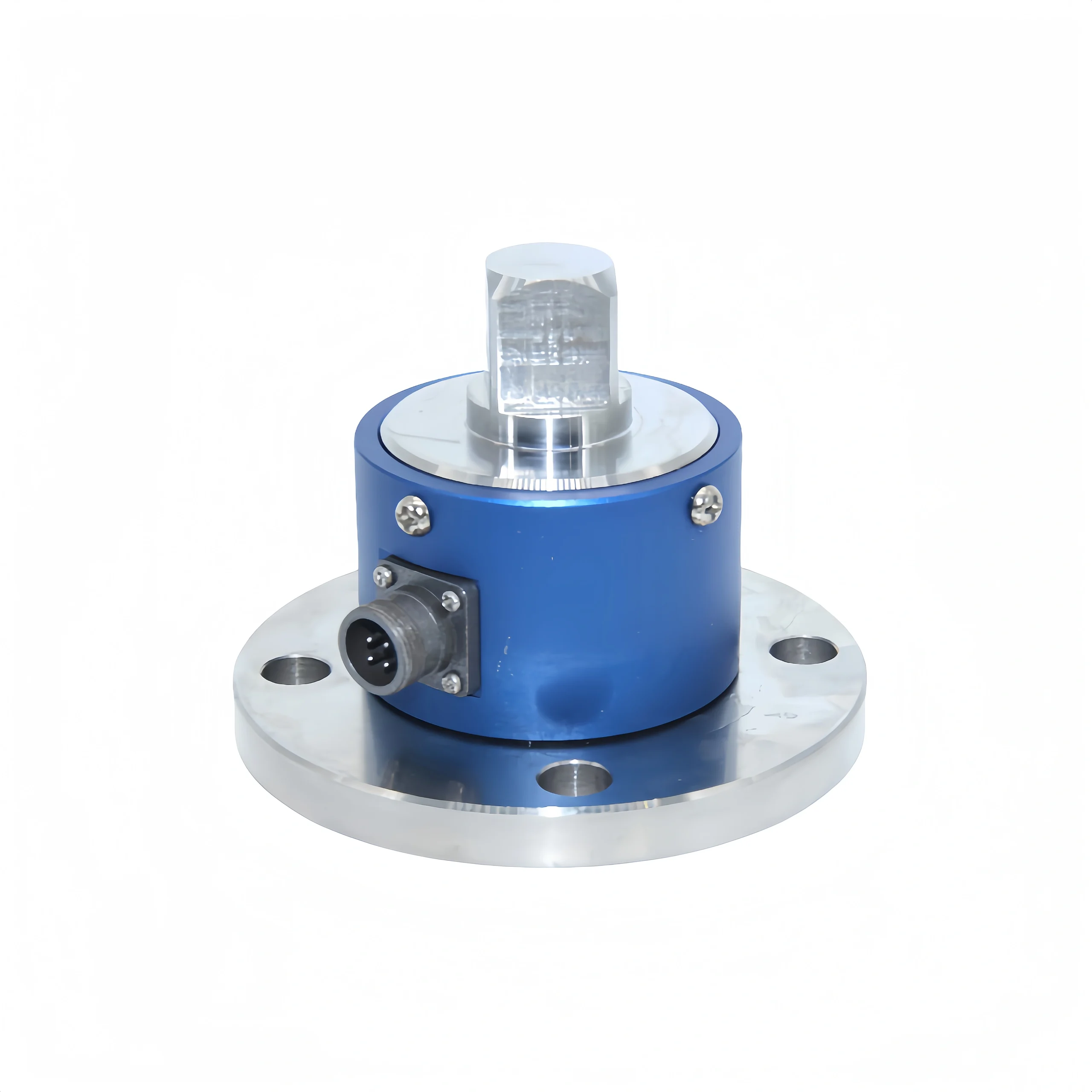
For customers requiring a shorter axial dimension, a disc-type torque sensor is available. This sensor has no output shaft at either end. It significantly reduces the axial dimension. It is suitable for monitoring and measuring transmission. And it breaks components in the automotive industry. For customers with less stringent shaft requirements, a standard torque sensor is available.
Customization
To meet diverse customer requirements in terms of form, we can customize torque sensors. function and signal quality. To meet your specific needs. Sino-Inst has many years of experience in the torque industry testing. And we offer many custom torque sensors.
Perform Field Testing and Verification
It’s necessary to conduct field testing and verification. Ensure it meets measurement requirements. This can be done by installing the torque sensor in the actual application scenario. A torque transducer should undergo a series of tests. To assess its measurement accuracy and stability. If the measurement results do not meet the requirements, the sensor can be adjusted or replaced. Ensure it meets actual requirements.
Brand and After-Sales Service
Choosing a brand with a good reputation is crucial. It ensures stable torque sensor performance. Well-known brands typically have high standards in production quality. After-sales service is also an important factor when selecting a torque sensor. High-quality after-sales service ensures timely repair in the event of a device failure.