4–20 mA is the mainstream analog transmission standard in industry, and proper 4–20 mA wiring directly determines signal stability. In the field, wiring errors often lead to value drift and false open-circuit alarms. The following section breaks down the wiring logic and practical implementation points for two-wire, three-wire, and four-wire systems.
What Is a 4–20 mA Signal Output?
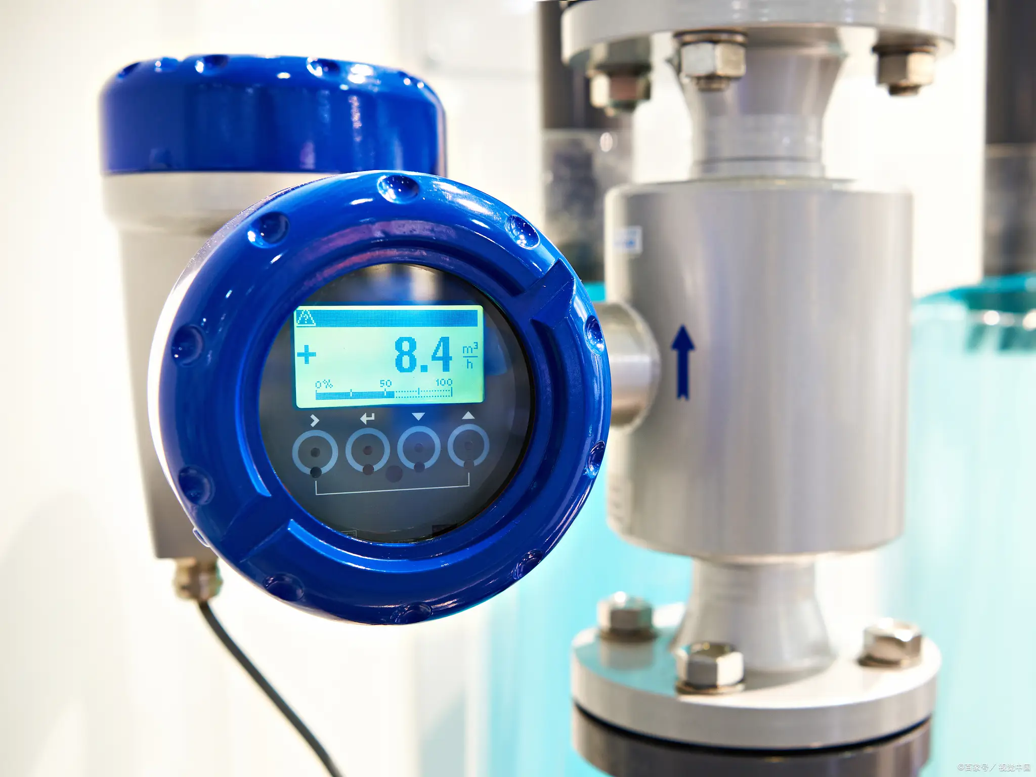
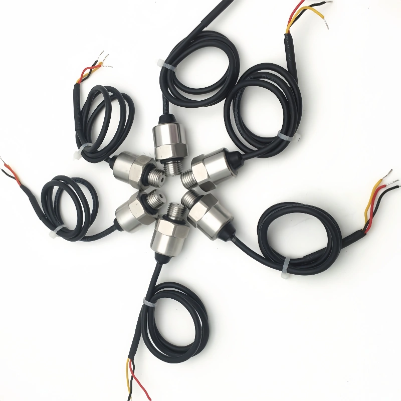
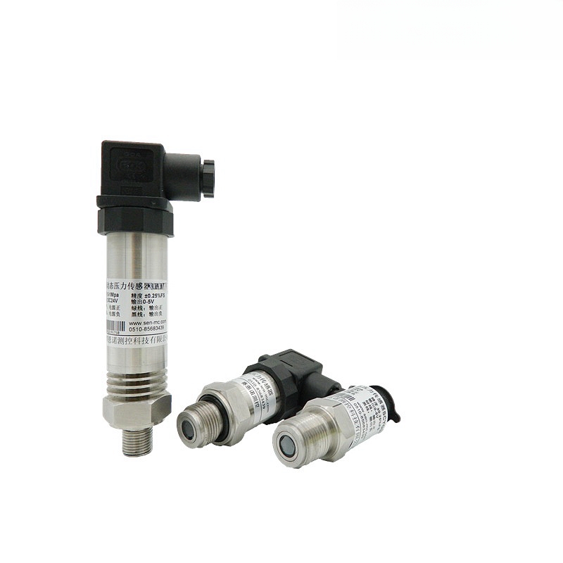
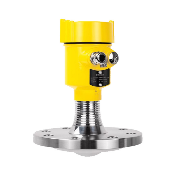
The 4–20 mA signal output is a standard analog current transmission signal widely used in the field of industrial automation and is commonly employed by various sensors and transmitters.
This signal uses 4 mA as the lower limit (zero point) of the measurement range and 20 mA as the upper limit (full scale). The current in the intermediate range of 4 to 20 mA varies linearly with the measured physical quantity—for example, as values for parameters such as pressure, temperature, flow rate, and liquid level increase, the output current approaches 20 mA.
Compared to voltage signals, current signals aren’t affected by resistance losses in the wiring during transmission. They don’t attenuate as much over long distances, hold up better against electromagnetic interference, and work well in messy factory wiring environments.
The 4 mA zero-point design doubles as a diagnostic tool: if a wire breaks or something fails, the loop current falls below 4 mA, so the control system can spot problems quickly and tell the difference between a “zero reading” and an actual equipment or wiring fault.
Signal transmission uses a two-wire setup, where the same pair of wires feeds power to the transmitter and carries the analog signal. This keeps field wiring straightforward and brings installation costs down. On the receiving end, you’ll usually find devices like PLCs or digital displays — they drop a sampling resistor into the circuit to convert the current to voltage, then handle data acquisition and monitoring from there.
4–20 mA Wiring
I. Two-Wire 4–20 mA
1. Working Principle
The two-wire system is the most commonly used signal transmission method in industry, relying solely on two wires to simultaneously power the instrument and transmit the signal.
The instrument is connected in series with a 24 V DC circuit. After measuring physical quantities such as pressure, temperature, and liquid level, it linearly converts them into a standard 4–20 mA current signal, where 4 mA corresponds to the zero point and 20 mA corresponds to full scale.
By leveraging the characteristic that the current signal remains unaffected by line resistance, stable transmission is achieved; simultaneously, a line break can be detected by monitoring the 4 mA baseline.
2. Wiring Method
The whole circuit is just a 24 V power supply, a field transmitter, and a control room acquisition module (PLC or digital display) all wired in series.
You connect the positive terminal of the power supply to the positive terminal of the instrument, then run the negative terminal of the instrument to the signal terminal on the analog module, and finally connect the negative terminal of the module back to the negative terminal of the power supply — that completes the loop.
Each instrument needs its own independent circuit; you can’t wire them in parallel. The wiring is straightforward and you don’t have to worry about figuring out complicated polarities.
3. Advantages and Disadvantages
Advantages:
The wiring is dead simple with only two cables, so installation and material costs stay low. Current signals shrug off interference pretty well, which means you get accurate transmission even over long runs.
It has built-in open-circuit detection, which makes life easier for operators and maintenance crews. The circuit doesn’t draw much power, so it works fine in intrinsically safe explosion-proof environments.
Disadvantages:
One circuit can only handle one instrument, so if you’ve got a bunch of measurement points the wiring costs add up. There are limits on load resistance, and if you stretch the cables too far you can run into signal distortion and not enough power getting through.
You can’t split the signal into multiple outputs either, so expanding the system down the road is a bit of a pain.
4. Application Scenarios
You’ll see this setup all over the place with standard industrial transmitters. It handles the usual pressure, level, flow, and temperature measurement points in industries like chemicals, power generation, water treatment, and oil and gas.
It really shines in explosion-proof areas and in simple outdoor monitoring setups where the sensors are a long way from the control room. It’s basically the bread-and-butter signal transmission solution for automation control systems.
II. Three-Wire 4–20 mA
1. Working Principle
The three-wire system employs a configuration with an independent power supply and a shared negative terminal, consisting of three wires: power positive, signal positive, and common negative.
The instrument is powered separately by a 24 V power supply, which provides sufficient power to ensure stable operation of the internal sensing circuitry. After measuring the parameters, it outputs a 4–20 mA current signal.
The signal loop and power supply loop share a common ground wire, achieving relative separation between power supply and signal transmission.
2. Wiring Method
The instrument’s positive power terminal is connected to the 24V power supply’s positive terminal; the common negative terminal is connected to both the power supply’s negative terminal and the PLC module’s negative terminal; and the signal positive terminal is connected separately to the analog signal acquisition port.
The common negative terminals of multiple instruments can be connected in parallel, resulting in neat wiring and ensuring that the power supply and signal circuits do not interfere with each other.
3. Advantages and Disadvantages
Advantages:
There’s plenty of power on tap, so you can run instruments that draw a fair bit of current. Load restrictions are pretty relaxed, and the signal stays stable even when you have to run cables a long way. Wiring up multiple points is less of a headache. Zero-point drift is barely an issue, and you get better overall accuracy.
Disadvantages:
You need an extra cable compared to two-wire systems, which bumps up wiring costs a bit. The shared ground wire can pick up common-mode interference, so you have to get your shielding and grounding right. Retrofitting for explosion-proof use and getting everything commissioned is also more involved.
4. Application Scenarios
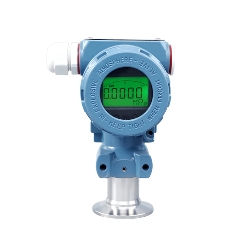
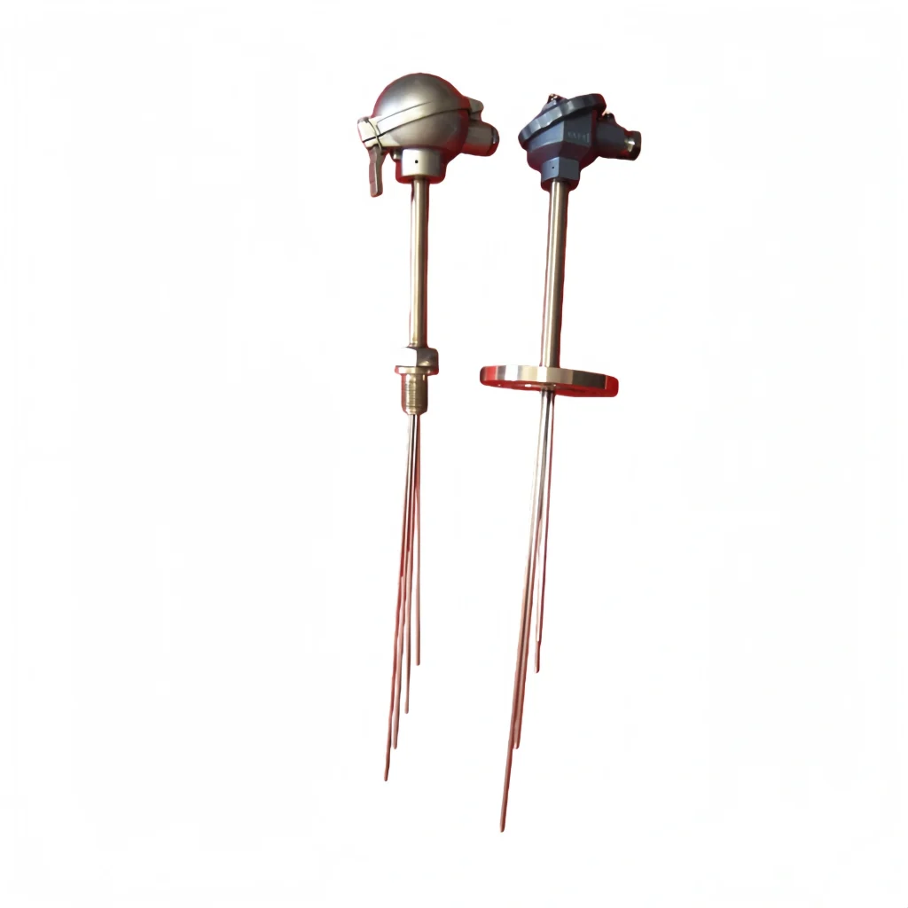
This approach works best for sensor devices that have built-in displays, need high precision, or consume a moderate-to-high amount of power — think high-precision temperature meters, water turbidity sensors, and integrated unit monitoring instruments.
You’ll typically find them in water treatment plants, metallurgical facilities, and workshop automation setups. They’re a good fit for indoor environments where measurement points are clustered together and you don’t have to deal with strict explosion-proof requirements.
II. Three-Wire 4–20 mA
1. Operating Principle
The three-wire system employs a configuration with a separate power supply and a common negative terminal, consisting of three wires: power positive, signal positive, and common negative.
The instrument is powered separately by a 24 V power supply, which provides sufficient power to ensure stable operation of the internal sensing circuitry. After detecting the parameters, it outputs a 4–20 mA current signal.
The signal circuit and the power supply circuit share a common ground wire, thereby achieving relative separation between the power supply and the signal.
2. Wiring Method
Connect the instrument’s positive power terminal to the positive side of the 24V supply. The common negative terminal goes to both the power supply’s negative terminal and the PLC module’s negative terminal.
The signal positive terminal runs on its own straight to the analog signal input. You can tie the common negative terminals together across multiple instruments, which keeps the wiring neat and prevents the power and signal paths from interfering with each other.
3. Advantages and Disadvantages
Advantages:
The power supply has enough headroom to run instruments that pull a lot of current. Load restrictions don’t really hold you back, and the signal stays solid even when the cables run a long way. Managing multiple measurement points is less of a hassle. Zero-point drift hardly shows up, and the accuracy is a step up from what you’d get with simpler setups.
Disadvantages:
You need one more cable than a two-wire setup, which pushes wiring costs up a little. The shared ground wire can catch common-mode interference, so you’ve got to pay attention to shielding and grounding. Retrofitting for explosion-proof use and getting the system commissioned is also more of a hassle.
4. Application Scenarios
This works best for sensor devices that come with displays, need tight precision, or draw a moderate-to-high amount of power — things like high-precision temperature meters, water turbidity sensors, and integrated unit monitoring instruments.
You’ll see them a lot in water treatment plants, metallurgy operations, and workshop automation equipment. It’s a good match for indoor environments where measurement points are packed together and you don’t have to worry about strict explosion-proof requirements.
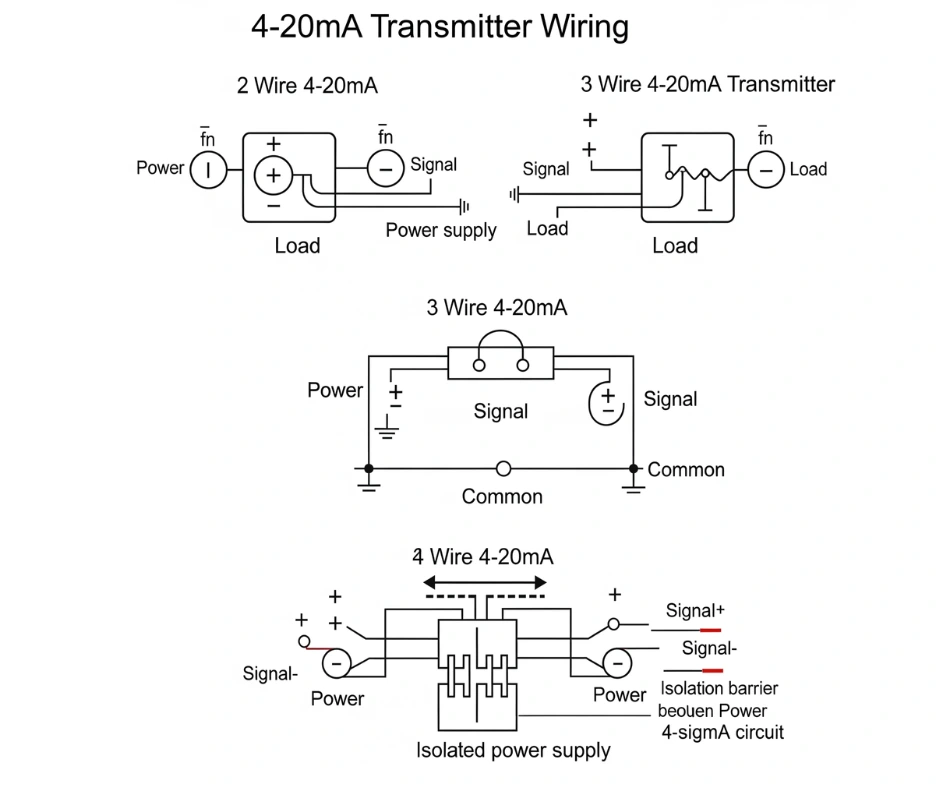
III. Four-Wire 4–20 mA
1. Operating Principle
The four-wire system achieves complete electrical isolation between the power supply circuit and the signal circuit, with two wires dedicated to power supply and two wires dedicated to signal transmission.
The instrument draws power independently, and the power supply is not limited by the signal. After the acquired process parameters are converted into a 4–20 mA current signal, they are transmitted via independent signal wires. The power supply and signal do not interfere with each other, completely eliminating loop interference issues.
2. Wiring Method
The instrument’s four terminals are completely separate from each other. The positive and negative power terminals hook up to an external 24V supply for independent power delivery, while the positive and negative signal terminals get wired separately to the data acquisition gear in the control room.
You can run the power lines in parallel, but each signal line needs its own dedicated connection to the system. Never short the power ground wire and the signal ground wire together — keeping the circuits fully isolated is the whole point.
3. Advantages and Disadvantages
Advantages:
The electrical isolation is rock-solid, so you don’t have to deal with common-mode interference, and you can push high-precision signals over long distances without issues.
There’s plenty of power available, which means you can drive high-power, multifunctional smart instruments without breaking a sweat. It also supports daisy-chaining or serial data collection from multiple devices, gives you room to expand the signal path later, and makes troubleshooting a lot less painful when something goes wrong.
Disadvantages:
You need a ton of cabling, so installation and material costs hit the highest level among the three wiring types. The wiring itself is complicated and eats up a lot of space in cable trays.
Getting it integrated in explosion-proof environments is no walk in the park either. If you’ve only got a handful of measurement points, the cost-per-point just doesn’t make sense.
4. Application Scenarios
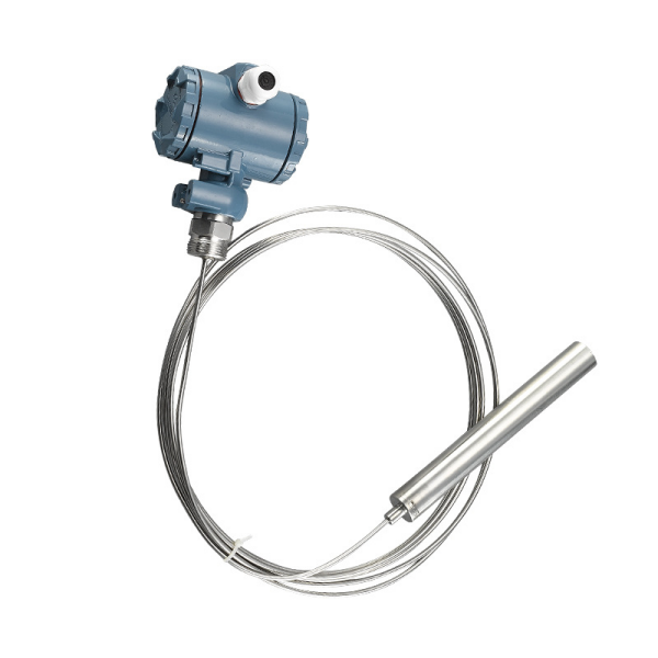
This setup is mainly found in high-precision, multifunctional industrial smart analyzers — flue gas analyzers, multi-parameter water quality analyzers, and flow meters that come with purge or control functions are typical examples.
It’s widely used in professional monitoring situations where measurement accuracy and equipment functionality are non-negotiable, like environmental protection monitoring stations, chemical analysis booths, and denitrification systems in thermal power plants.
Differences Between 4–20 mA Two-Wire and Four-Wire Systems
1. Differences in Cabling and Power Supply Logic
The two-wire system gets by with just two conductors, where power and signal ride on the same current loop — the transmitter draws its operating power straight from that loop current.
The four-wire system, on the other hand, uses four separate conductors: two for bringing in power and two for sending out the signal independently. The power loop and signal loop are completely separate, with no shared wiring between them.
2. Differences in Operating Principles
With a two-wire setup, the loop current stays within the 4–20 mA band, and the exact current at any moment reflects whatever you’re measuring. The 4 mA floor does more than mark zero — it’s also what keeps the instrument powered up and running.
In a four-wire arrangement, the device draws from its own separate power supply, so it gets a steady feed regardless of the signal. The output current is used only to transmit the measurement value, and the power side operates completely independently of the 4–20 mA loop.
3. Differences in Wiring Methods
In a two-wire system, the transmitter, power source, and data acquisition module are all wired in series on a single loop. Each transmitter needs its own pair of wires, and you can’t hook multiple units in parallel on the same loop.
With a four-wire system, several transmitters can share the same power supply line in parallel, while each signal line runs on its own to a PLC or secondary device. Just be careful not to tie the power ground and signal ground together.
4. Differences in Advantages and Disadvantages
The two-wire system has a few things going for it: fewer cables to deal with, lower wiring costs, built-in wire break detection since the current drops below 4 mA if something’s wrong, and it works well in intrinsically safe explosion-proof environments.
The downsides are that the loop can’t handle much load, the instrument’s power consumption is capped by what’s available in the 4–20 mA range, and you’re stuck with only one data acquisition device per loop.
The four-wire system brings its own set of strengths: no common-mode interference to worry about, high transmission accuracy, enough power to drive high-power instruments, and the ability to string multiple display devices in series on the signal line.
The trade-offs are that it burns through more cable, installation costs are higher, and getting the explosion-proof configuration right is more complicated.
5. Differences in Applicable Equipment and Operating Conditions
The two-wire system is suitable for pressure, level, standard temperature, and conventional flow transmitters, and is commonly used in chemical plants, oil and gas explosion-proof zones, and for simple outdoor measurement points over long distances.
The four-wire system is commonly used for gas analyzers, multi-parameter water quality analyzers, and large intelligent instruments with purge/heating functions, and is suitable for high-precision, high-power-consumption measurement scenarios such as environmental monitoring and online analysis cabins.
Selection Guide
1. Two-wire system: Only two wires; power and signal share the same circuit, reducing wiring costs. Suitable for standard pressure, level, and temperature transmitters, as well as explosion-proof applications and scenarios where PLC modules are directly powered; cannot drive high-power probes due to load limitations.
2. Three-wire system: This one uses three wires — positive power, a shared negative, and a signal output — which gives you more power to work with than a two-wire setup. It works well for sensors that have built-in amplification circuits or low-power heating elements, and it’s fine for short runs inside control cabinets. Just keep in mind that voltage drops across long ground wires can throw off your accuracy.
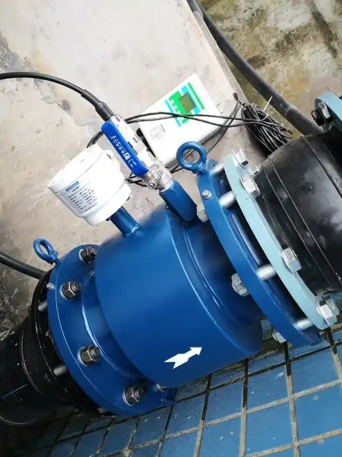
3. Four-wire system: Power and signal lines are completely independent of each other, so you get plenty of power and solid resistance to interference. You’ll see this on electromagnetic flowmeters, high-precision analyzers, equipment in areas with strong electromagnetic fields, and anywhere you need to push signals over long distances. The catch is that cable costs are noticeably higher.
4. For intrinsically safe applications, stick with two-wire systems if you can. The explosion-proof design gets messy when you have to deal with three-wire or four-wire systems that use independent power supplies.
5. If you’re working in an environment with strong electromagnetic interference or you need high-precision measurement, go with a four-wire system to keep power supply noise from bleeding into your signal.
6. When the data acquisition card is the only power source available and there’s no external 220V supply to tap into, a two-wire system is pretty much your only choice.
7. If the instrument has power-hungry components like pumps or heating elements built into it, you’ll need to step up to either a three-wire or four-wire system to handle the extra load.
8. For cable lengths exceeding 500 meters, prefer a four-wire system; for short distances with a single instrument, use a two-wire system to reduce costs.
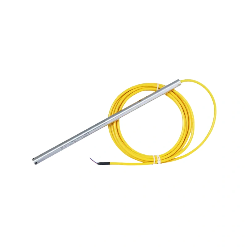
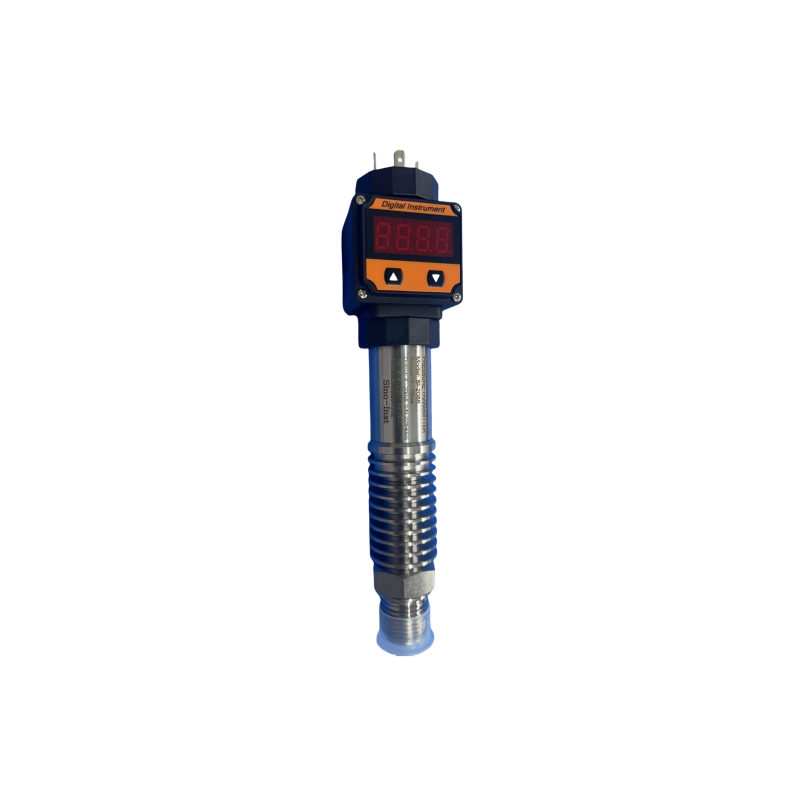
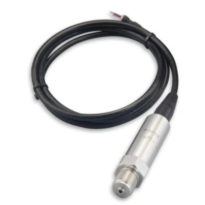
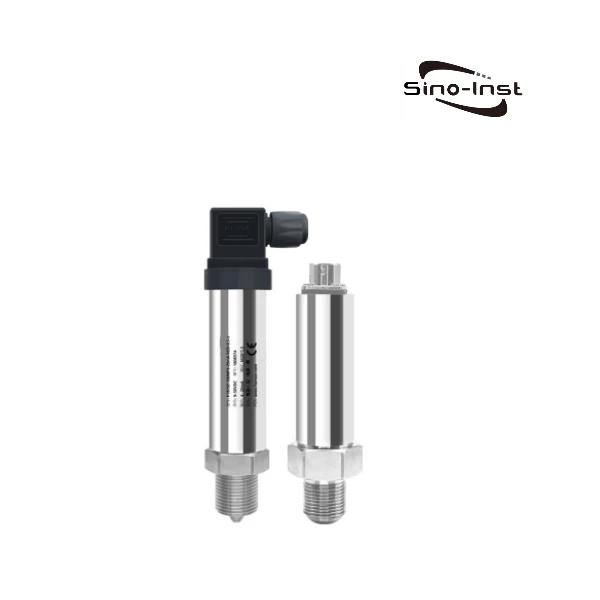
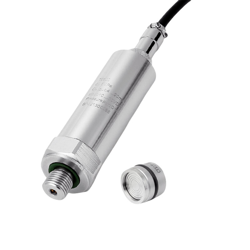
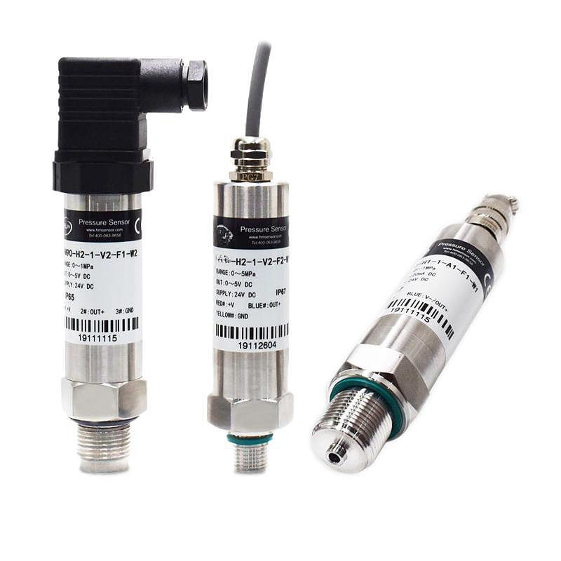
The full range of Sino-Inst 4–20 mA transmitters covers two-wire, three-wire, and four-wire configurations, meeting the requirements of all types of operating conditions, including pressure, level, flow, and water quality analysis.
In addition to standard analog current signals, the entire series of instruments simultaneously supports digital signal outputs such as RS485 and HART, accommodating both traditional data acquisition systems and intelligent digital control platforms.
We provide professional, one-on-one technical support for wiring and instrument selection, and supply cables, isolation barriers, and intrinsically safe explosion-proof accessories as needed, balancing on-site installation costs with long-term measurement stability.
If you have any needs regarding instrument selection or customized wiring solutions, please feel free to contact us at any time to obtain a complete technical proposal and quote.