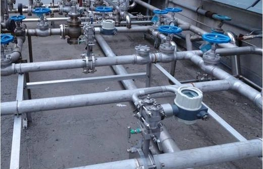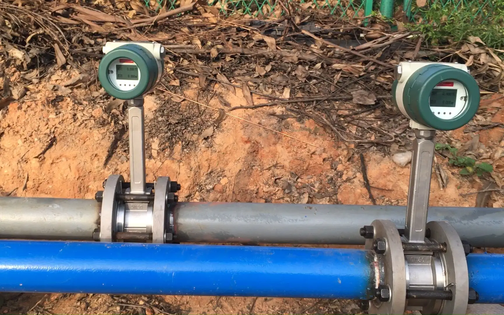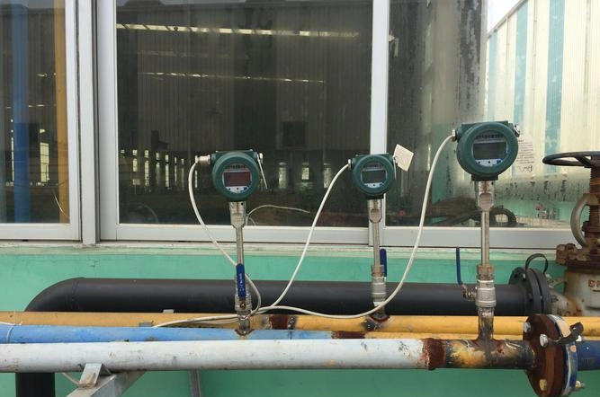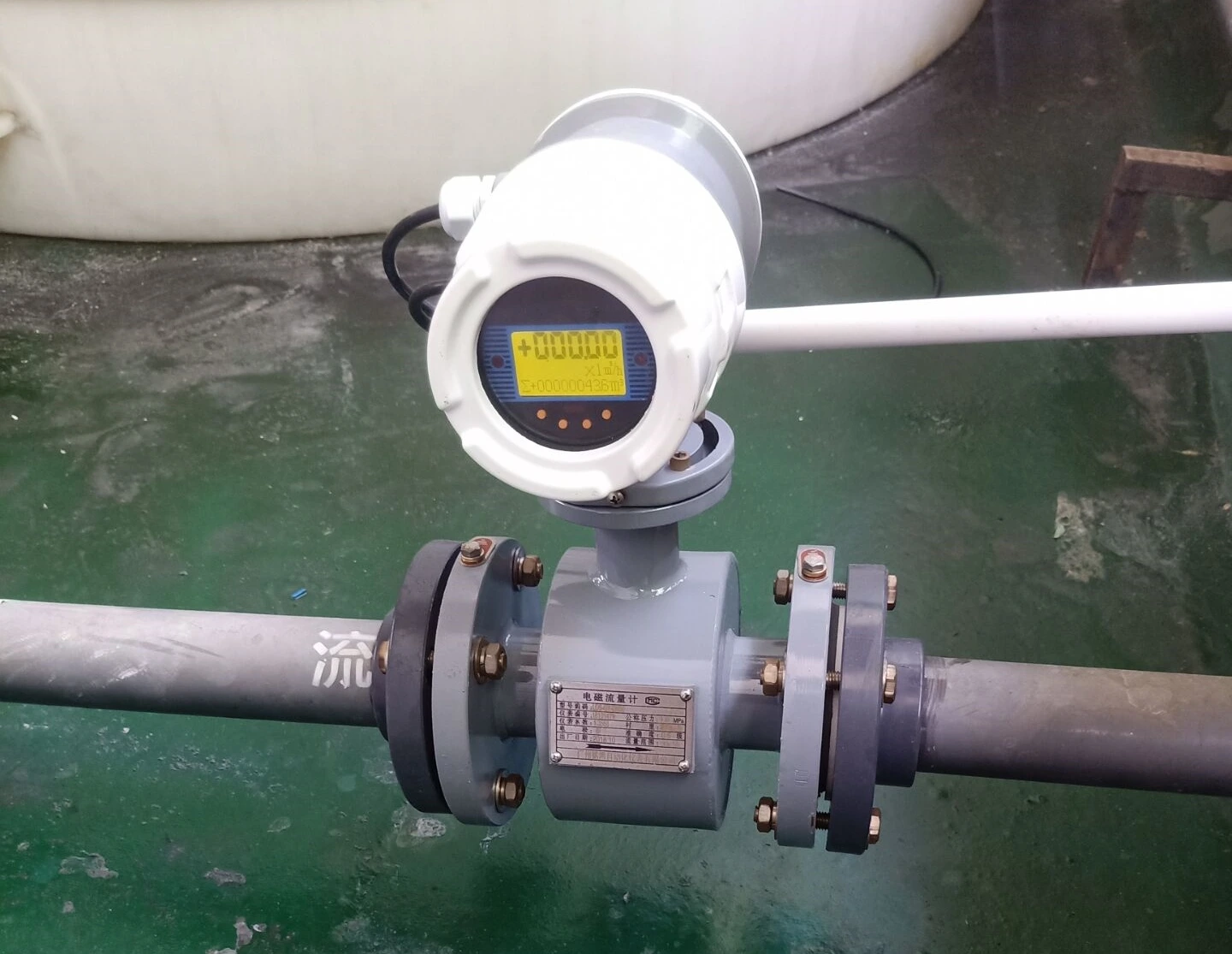
Orifice flow meters are the mainstream devices for industrial differential pressure flow measurement; however, during long-term operation, wear on the orifice plate and abnormalities in pressure tapping can introduce measurement errors.
Standardised calibration is a key means of controlling measurement uncertainty and ensuring the reliability of process control and commercial settlement. This article discusses the key points of orifice flow meter calibration.
What is an Orifice Flow Meter?
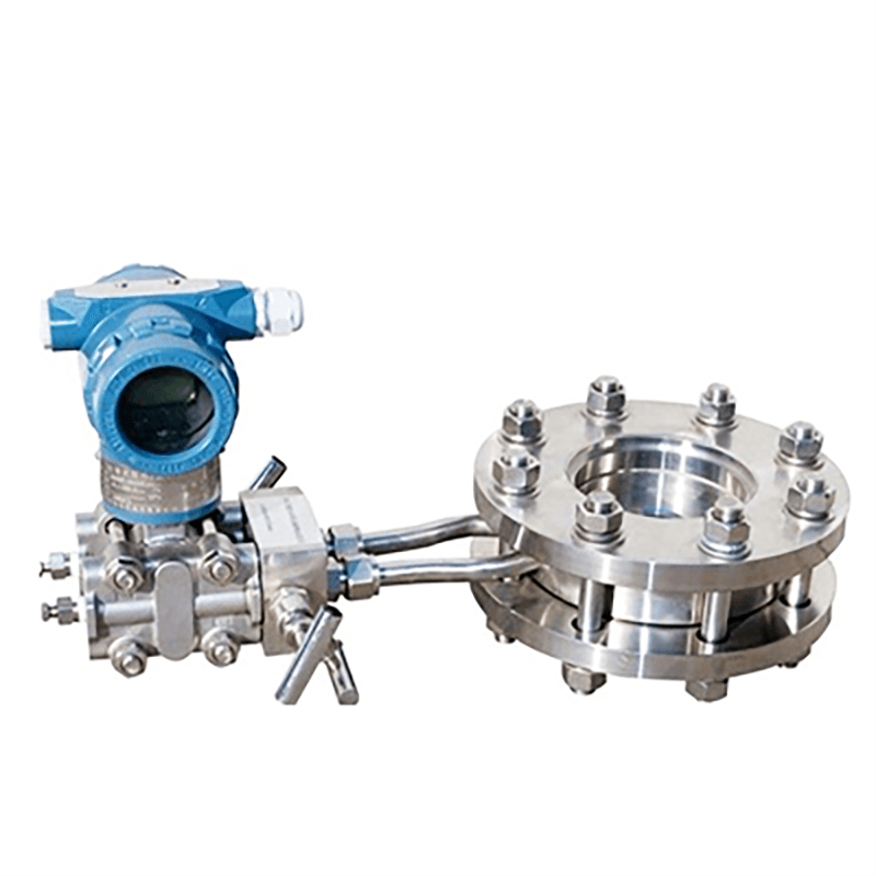
The orifice flow meter belongs to the family of differential pressure flowmeters and is widely used in industrial settings to measure the volumetric flow of liquids, gases and steam running through pipelines.
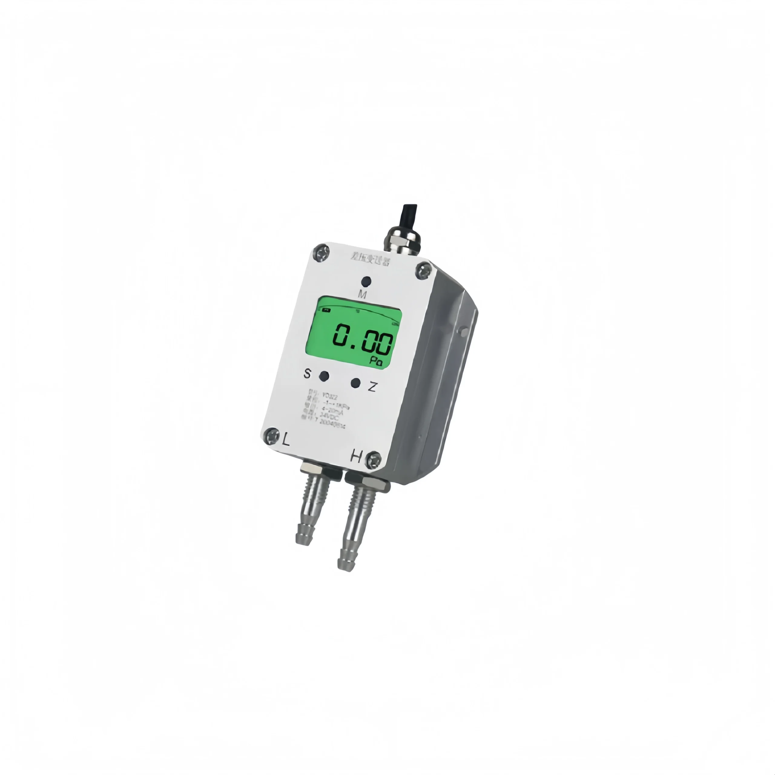
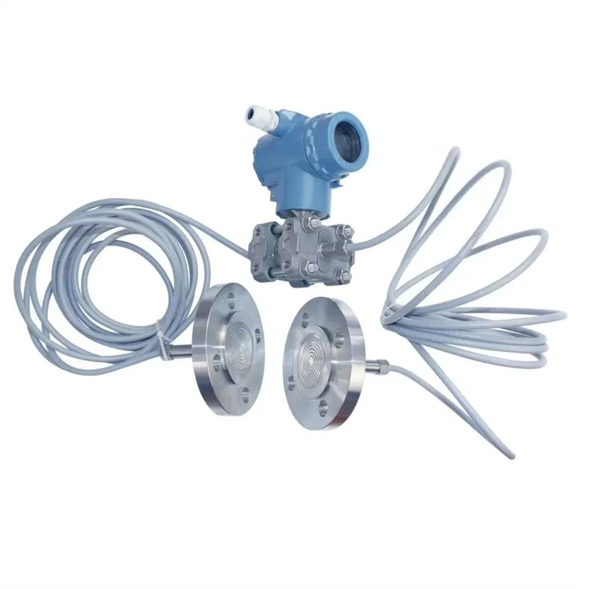
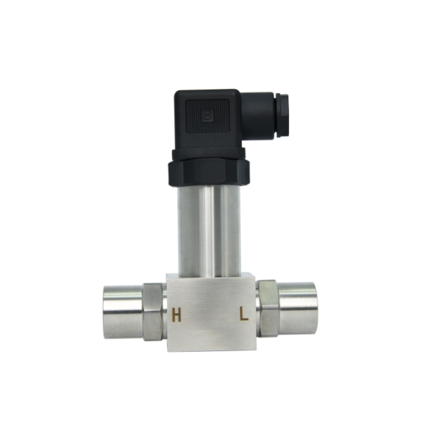
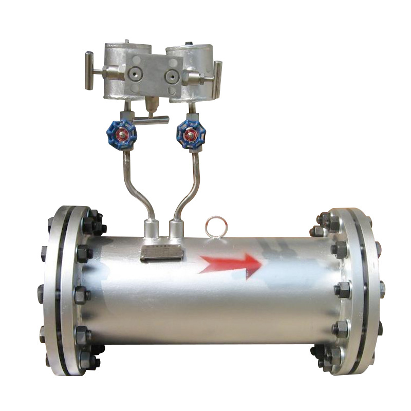
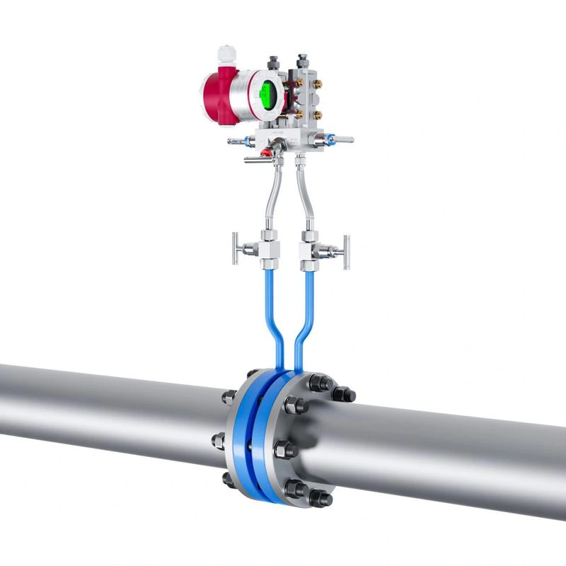
It is made up of three main parts: the throttling element (that is, the orifice plate), the pressure tapping points, and a differential pressure transmitter. What makes it popular is its simple construction, its low price, and the fact that installation and upkeep present little difficulty.
How the Orifice Flow Meter Works
The meter works on the principle of throttling. As the fluid travels along the pipe and meets the orifice plate fitted inside, the flow passage suddenly contracts. Passing through this restriction, the fluid speeds up and its static pressure falls, which sets up a stable pressure difference between the two sides of the plate.
The bigger the flow, the bigger this pressure difference becomes. The differential pressure transmitter detects this signal, and the actual flow rate is then calculated from the appropriate equation, with the fluid properties and the dimensions of both orifice plate and pipe fed into the calculation.
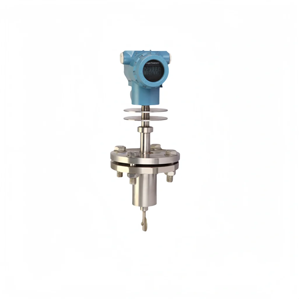
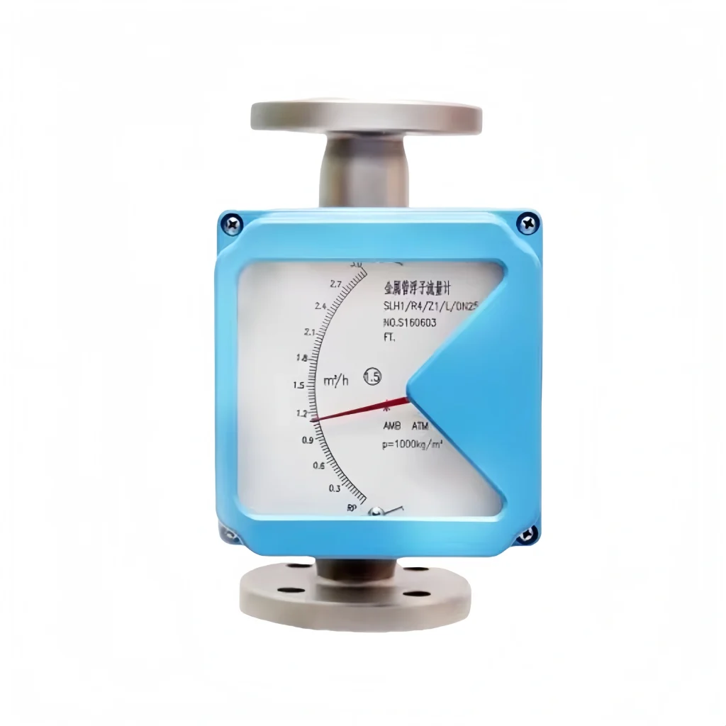
Factors affecting the accuracy of orifice plate flow meters
1. Fluid condition. Distorted velocity distribution, vortices, impurities, bubbles or two-phase flow in the medium disrupt the conditions for single-phase measurement, leading to measurement errors.
2. Orifice plate machining and installation. If the sharp edges have worn or corroded, if the plate has been mounted the wrong way round or set off-centre, or if a gasket sticks out into the bore, the discharge coefficient will no longer be what it should be, and the differential pressure reading will be off.
3. Insufficient straight pipe runs. Where bends, valves or similar fittings sit too close to the orifice plate on either side, the flow pattern gets disturbed before or after the restriction, and the measured flow ends up deviating from the true value.
4. Faults in the pressure tapping system. Blockages, air leaks or liquid accumulation in the pressure tapping lines, as well as vapourisation and condensation of the medium, lead to distortion of the differential pressure signal.
5. Changes in medium operating conditions. Fluctuations in the fluid’s temperature and pressure alter the medium’s density, whilst changes in viscosity, if not compensated for, will reduce measurement accuracy.
6. Reynolds number limitations. When the Reynolds number falls below the lower limit, the discharge coefficient becomes unstable; at low flow rates, the differential pressure is weak, resulting in an increased relative error.
7. Differential pressure instrumentation. Zero-point drift in the transmitter and inappropriate range selection result in secondary measurement errors.
Common flowmeter calibration methods
Geometric inspection method (dry calibration)
Remove and clean the orifice plate, then use precision measuring instruments to measure parameters such as the orifice diameter, plate thickness, inlet sharpness, pressure tapping holes and pipe internal diameter.
Calculate the flow coefficient by comparing these measurements with standards. This method does not require fluid testing and facilitates rapid on-site inspection; however, it cannot assess errors arising from installation or flow field conditions.
Laboratory flow calibration (wet offline calibration).
The orifice plate, pressure-taking tubes and differential pressure transmitter are installed in a standard flow test rig. Five or more flow points are selected, and flow and differential pressure signals are recorded simultaneously to calculate the discharge coefficient and measurement error.
This method is suitable for trade metering; however, it requires the removal of the equipment.
On-site actual flow comparison calibration
The orifice plate is not removed; instead, a high-precision standard flowmeter is connected in series to the pipeline. Under stable operating conditions, multi-point comparison readings are taken to assess system error.
This method closely reflects actual operating conditions and avoids the need to remove the meter, but is susceptible to the influence of straight pipe sections and flow patterns.
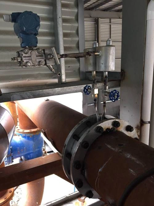
Orifice Flow Meters Calibration
Pre-calibration preparations
1. Inspect the orifice plate and pipework
Check that the sharp edges of the orifice plate are intact, with no corrosion, deformation or scratches.
Verify the condition of the upstream and downstream straight pipe sections, pressure taps, flanges and seals; clear any debris from the interior of the pipework; confirm that the installation is concentric and the flow direction markings are correct; gaskets must not protrude into the pipe.
2. Prepare supporting equipment
Confirm that instruments for differential pressure, pressure and temperature are within their valid calibration period.
Inspect the pressure-taking lines, valves and data acquisition devices to ensure that power supply and signal lines are functioning correctly and that the piping is free from blockages or leaks; prepare the calibration record forms.
3. Determine fluid characteristics
Identify the type of calibration medium and obtain parameters such as density and viscosity under operating conditions; determine the calibration flow points in conjunction with the process conditions and match them to the corresponding calibration operating conditions.
Calibration Process
Zero Point Calibration
1. This is a static calibration procedure, the purpose of which is to eliminate measurement errors caused by zero-point drift in the differential pressure transmitter and differences in liquid column height in the pressure-taking lines.
2. During the procedure, close the upstream and downstream shut-off valves on the pipeline and open the balancing valve on the three-valve manifold to equalise the pressure in the transmitter’s positive and negative pressure chambers; inspect the piping to ensure there are no air bubbles, blockages or leaks.
3. Once the pressure has stabilised completely, use a handheld programmer to set the transmitter’s zero point, ensuring that zero differential pressure corresponds to a 4 mA output.
4. After calibration, verify the results multiple times to ensure the instrument’s zero point remains stable in the absence of flow; take great care during the operation to prevent damage to the transmitter diaphragm caused by high-pressure surges on either side.
Low-flow calibration
1. In the lower range of the measurement span, the differential pressure across the orifice plate is very low at low flow rates, making it susceptible to interference from fluid noise and pipeline disturbances; this is a section where errors frequently occur.
2. Set the flow to a stable low rate on the standard calibration apparatus, wait for the fluid conditions to stabilise, and simultaneously record the standard flow reading, the orifice plate differential pressure and the flow indication.
3. Compare the theoretical differential pressure with the value actually measured to check whether the instrument’s square-root extraction and low-flow cut-off settings are behaving as they should, and adjust the flow coefficient if the comparison indicates it needs correcting.
4. Carry out a repeatability check at the bottom end of the range, so that you can be confident the meter still gives dependable readings when the flow is low.
Multi-point Calibration
1. This is the basic method used to calibrate the whole orifice plate flowmeter system. Pick five to seven flow points spread fairly evenly over the full range, making sure the minimum, typical and maximum flows are all included.
2. Once the flow has been brought to each point, let it settle and hold steady for long enough, and record the relevant operating parameters — the standard flow rate, the differential pressure across the orifice plate, and the medium temperature and pressure — while the flow is stable.
3. From these readings, work out the indication error and repeatability at each point, draw up the differential pressure versus flow rate curve, and verify the discharge coefficient, correcting it if the results call for it.
4. This also gives you a picture of linearity across the full range. Problems in the mid-range — the kind that a single-point calibration would simply miss — tend to show up clearly once several points have been checked.
High-Flow Calibration
1. Conduct this near the flowmeter’s rated upper limit to verify the orifice plate’s throttling characteristics and the differential pressure transmitter’s full-scale output capability under high-velocity conditions.
2. Adjust the pipeline flow to a value close to the instrument’s maximum range; once operating conditions have stabilised, simultaneously compare the readings from the standard flowmeter and the orifice plate flowmeter.
3. High flow rates generate intense turbulence, which readily exposes defects such as orifice plate wear and scouring at the pressure tapping ports; this is used to verify the effects of full-scale output and pressure loss.
4. Correct the flow coefficient for the high-flow range to confirm the instrument’s measurement accuracy and stability at the rated upper limit operating conditions, whilst simultaneously inspecting the pipeline’s pressure-bearing integrity.
Post-calibration inspection
1. Visual inspection and installation check. Take a close look at the orifice plate — its sharp edges should be undamaged and undeformed, and the gaskets in good condition. Also confirm that the plate has been installed facing the right direction, that the straight pipe runs upstream and downstream are up to standard, and that the flanges, pressure taps and impulse lines are all tightly connected with no kinks or blockages anywhere.
2. Static zero check. Once the flow has been shut off completely, watch the differential pressure transmitter’s zero output for a while to make sure it stays put and doesn’t drift. While you’re at it, verify that the power and communications are functioning as they should and that no fault alarms are showing.
3. Checking calibration data and repeatability. Pull out the original calibration records and go through them. Then run a few repeated measurements under identical conditions to test repeatability — the indication error and repeatability figures should fall within the required limits. It’s also worth double-checking that configuration details, the orifice diameter in particular, have been keyed into the instrument correctly.
4. Leak test. Raise the system to its normal operating pressure and let it sit there. Go over the flanges, joints, valves and every other connection point for leaks, and make sure the pressure holds steady rather than dropping off on its own.
5. Dynamic commissioning and documentation review. Introduce the process medium and observe that the flow signal is stable with no fluctuations; ensure that ancillary components are in good condition, organise the calibration documentation, affix the compliance label and update the register.
FAQ
Which offers higher accuracy: an orifice plate flowmeter or a Venturi flowmeter?
In terms of measurement accuracy, Venturi flowmeters come out ahead of orifice plate flowmeters in most situations.
An orifice plate determines flow from the pressure difference generated across the plate, but this approach has its drawbacks: the plate edges wear with use, the pressure loss across it is considerable, and accuracy is usually only around ±1% to ±2.5%, often getting worse as time goes on.
Venturi flowmeters, on the other hand, guide the fluid through a gently tapered inlet and a long diffuser, so the flow passes through with far less disturbance. They stand up well to erosion and introduce minimal permanent pressure loss.
Typical accuracy figures fall between ±0.5% and ±1%, and their readings remain comparatively stable over the long term.
Media that can be measured by orifice plate flow meters?
1. Liquid media: these meters work well with clean single-phase liquids — water, oils and various solvents, for example. Liquids with a bit of contamination can still be measured, though the impurities tend to erode the orifice plate’s sharp edges over time, and that does have an impact on accuracy.
2. Gaseous media:single-phase gases are equally well suited, including air, natural gas and steam. Saturated and superheated steam are actually two of the most frequent applications.
3. Certain mixed media: Suitable for gas-liquid and liquid-solid two-phase conditions; however, generally only suitable for fluids with low solid content and low bubble content; not recommended for conditions with high levels of impurities.
4. Application limitations:Not suitable for media with high viscosity, strong corrosiveness, a large number of solid particles, or a tendency to form scale; such media may cause wear, blockage or scale build-up on the orifice plate.
Installation requirements for orifice plate flow meters?
- Straight pipe sections: make sure there is enough straight pipe run on both the upstream and downstream sides, with the upstream run being the longer of the two. Keep elbows, valves and similar fittings out of these sections where possible.
- Flow direction: the fluid must flow in the direction indicated by the markings on the orifice plate, with the sharp edge of the plate facing into the flow. Never install the plate the wrong way round.
- Piping:the pipe bore should match the orifice plate, and the inner wall of the pipe needs to be smooth. Take care that the gaskets do not stick out into the pipe.
- Pressure taps:for liquid service, locate the pressure taps on the lower side; for gas service, place them on the upper side, so that gas or liquid does not build up in the tapping lines.
- Environment: keep the installation away from locations with strong vibration, and make certain that the piping is firmly secured.
Types of differential pressure flow meters
A classic throttling differential pressure instrument; a pressure difference is generated as the fluid flows through the orifice plate. It features a simple structure, is low-cost and widely used, but suffers from high pressure loss and requires long straight pipe sections.
The fluid impacts a target plate to generate a differential pressure signal; suitable for high-viscosity and particulate-laden media, it can measure both liquids and gases, but is not suitable for low flow rates.
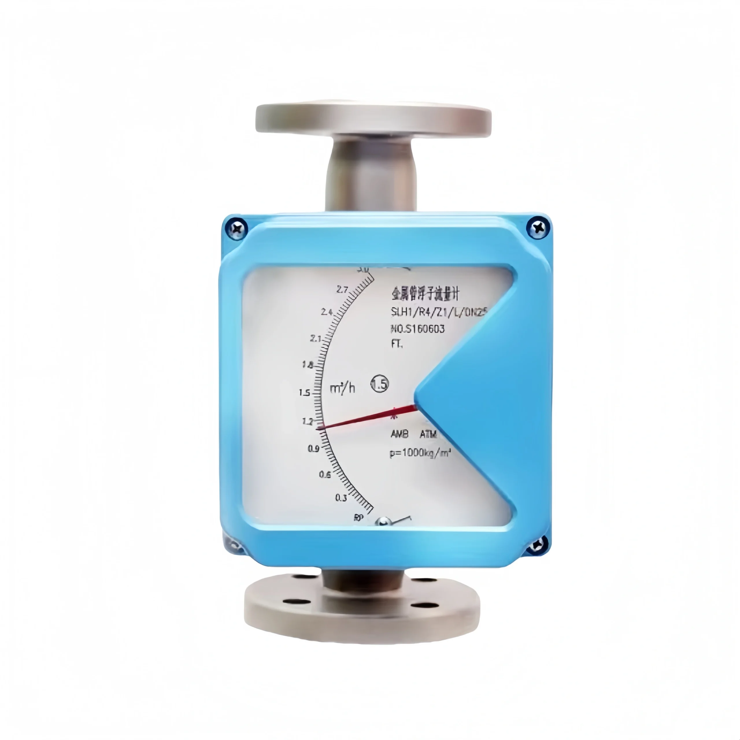
A variable-area differential pressure instrument in which a float is balanced against gravity by the differential pressure; its position indicates flow rate. It is commonly used for on-site indication of low flow rates.
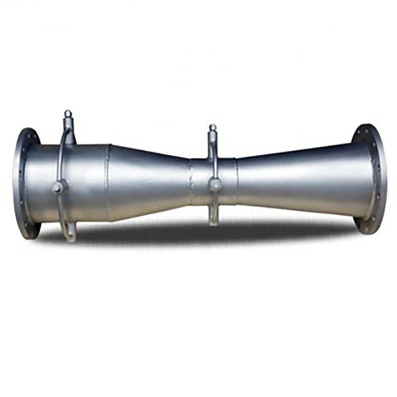
Consists of a contraction section, a throat and a diffusion section; the throat generates a differential pressure. It has low pressure loss and stable measurement, with better accuracy than orifice plates, but is relatively expensive.
V-cone flowmetre:
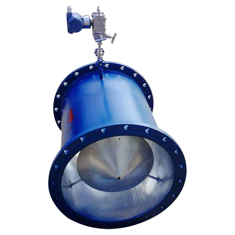
Features a V-shaped cone throttling element installed within the pipeline; the fluid flows around the cone to generate a differential pressure. It has a built-in flow straightening effect, requires minimal straight pipe runs, is resistant to fouling, has a wide measuring range and is suitable for high-temperature and high-pressure applications.
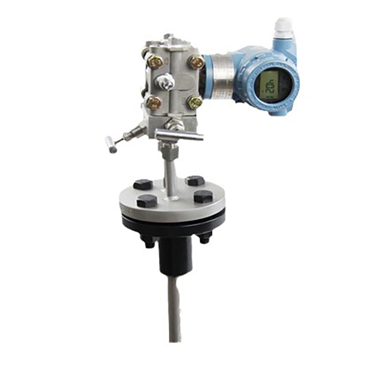
A differential pressure instrument utilising an average velocity tube, which takes pressure readings at multiple points along the measuring rod to obtain the average pressure across the cross-section, and calculates flow rate based on the differential pressure. It is easy to install and has low pressure loss, and is commonly used in large-diameter pipelines.
Standardised calibration is essential for ensuring stable measurement with orifice plate flowmeters.
Sino-Inst specialises in the field of flow measurement; in addition to differential pressure flowmeters, we offer a full range of flow instruments, including turbine, vortex, electromagnetic and ultrasonic models, suitable for various operating conditions in the chemical, water and energy sectors.
We provide a one-stop service for instrument selection and technical support, safeguarding your process control and trade metering.