Water level monitoring is a core component of process control in the water supply and environmental protection sectors. 4–20 mA standard current output water level sensors utilise a hydrostatic sensing mechanism to convert water levels linearly into a standard industrial analogue signal.
They offer the advantages of long-distance, interference-resistant transmission and the ability to detect cable breakage, making them suitable for continuous measurement in a variety of scenarios, including storage tanks, rivers and deep wells.
What is a 4–20 mA Signal Output?
A 4–20 mA signal output is a standard analogue current transmission signal widely used in the field of industrial automation, primarily for the long-distance transmission of measurement data between field sensors, transmitters and controllers.
This signal uses 4 mA as the lower limit (zero point) of the measurement range and 20 mA as the upper limit, corresponding to the minimum and maximum physical quantities within the device’s measurement range, such as process parameters including temperature, pressure, liquid level and flow rate.
Compared to voltage signals, current signal transmission offers greater resistance to interference; changes in line resistance do not cause signal attenuation, making it suitable for long-distance cabling in industrial settings, and it is compatible with both four-wire and two-wire transmitters.
The 4 mA reference zero point, distinct from 0 mA, enables line fault diagnosis. In the event of a broken wire or sensor failure, the loop current will fall below 4 mA, allowing the control system to rapidly identify the fault and trigger an alarm, thereby effectively distinguishing between the measurement zero point and equipment failure.
The entire transmission circuit requires only a series power supply, making wiring simple and ensuring high compatibility. Virtually all PLCs, DCSs and digital displays are equipped with 4–20 mA signal acquisition channels, making this a standardised analogue output format widely used in industrial process control.
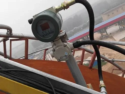
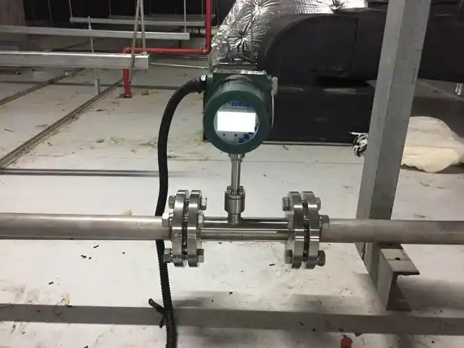
4–20 mA Water Level Transmitter
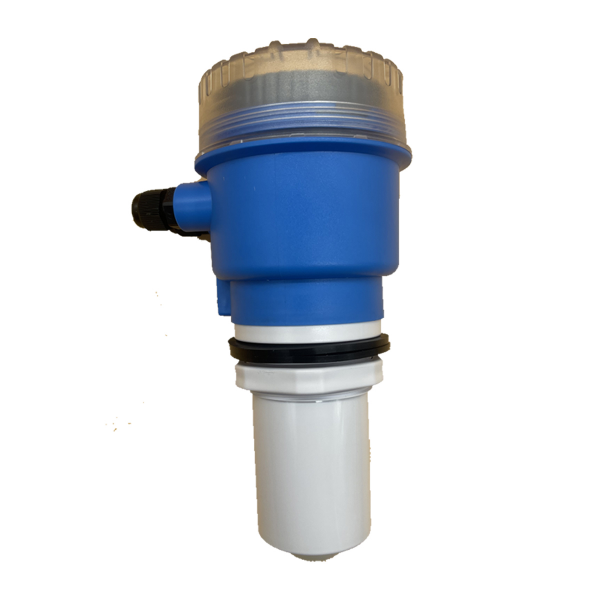
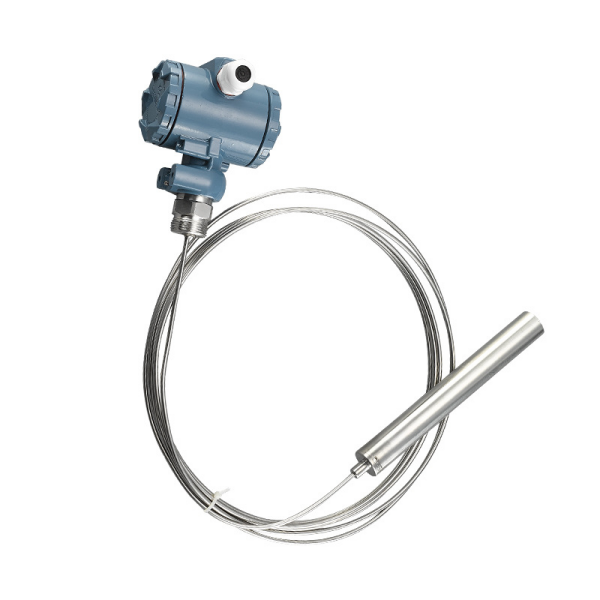
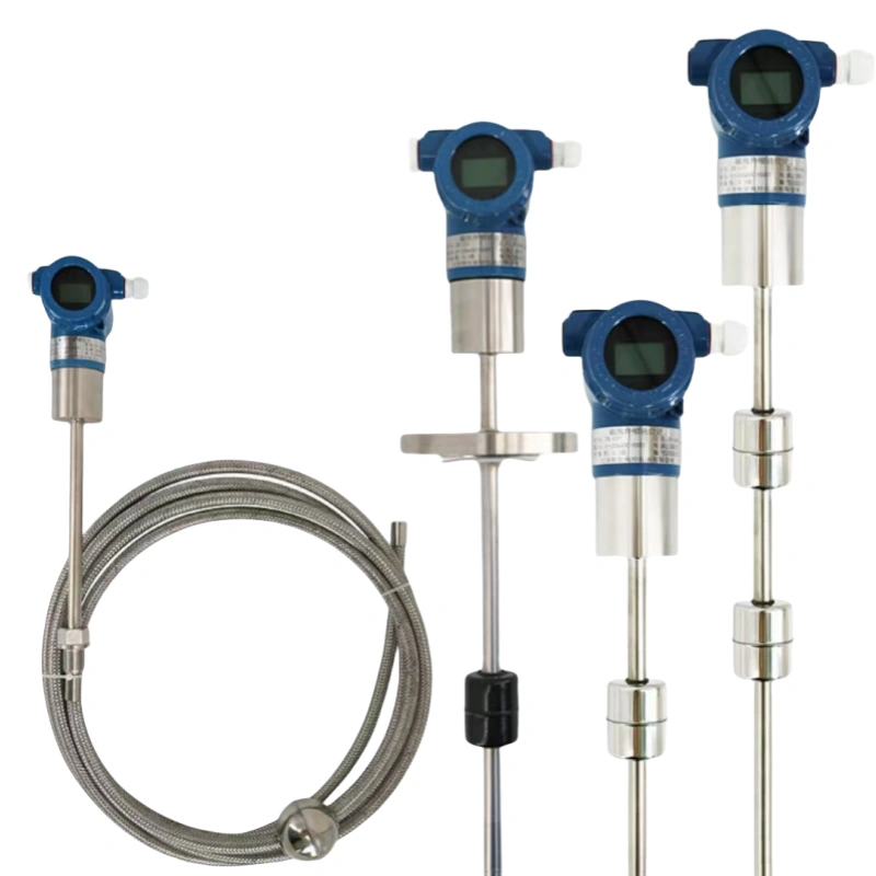
Submersible Static Pressure Water Level Transmitter
Principle of Operation
The level transmitter probe incorporates a high-precision pressure sensing element. When the probe is submerged at the bottom of the liquid, the static pressure generated by the liquid’s own weight acts upon the sensor’s diaphragm.
According to the formula for liquid pressure, there is a linear proportional relationship between pressure and liquid level height; A vented cable maintains real-time equilibrium with external atmospheric pressure, eliminating interference from ambient pressure on the measurement.
After the sensor core acquires the pressure signal, it is converted, amplified and processed, ultimately outputting a standard 4–20 mA current signal corresponding to the range from the minimum liquid level to full scale.
Advantages
1. Simple structure and easy installation; can be used immediately upon immersion in tanks, wells or reservoirs
2. No measurement dead zones; full-range linear detection of high and low liquid levels
3. 4–20 mA two-wire transmission, enabling long-distance cabling with resistance to electromagnetic interference
4. Wide measurement range, suitable for applications ranging from shallow tanks to wells up to 100 metres deep
5. Low cost with minimal maintenance requirements
6. Available with corrosion-resistant probe materials, suitable for clean water, sewage and mildly corrosive water bodies
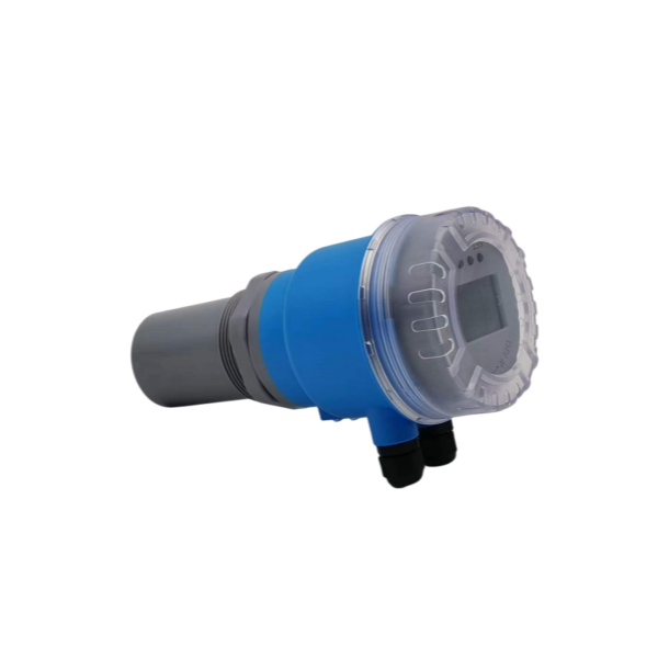
Ultrasonic Water Level Transmitter
Principle of Operation
Installed above the liquid surface, the sensor probe emits high-frequency ultrasonic pulses downwards. When the sound waves strike the water surface, they are reflected, forming an echo.
The probe receives the reflected signal; the internal circuitry records the time difference between the emission and reception of the sound waves. By applying the speed of sound, it calculates the vertical distance from the probe to the water surface, then uses an algorithm to convert this into the real-time liquid level height, outputting a standard 4–20 mA analogue current signal.
Advantages
1. Non-contact measurement: the probe does not come into contact with the water, eliminating issues of corrosion and blockages
2. Suitable for sewage and water containing impurities; no need for frequent sensor cleaning
3. Stable 4–20 mA signal, allowing direct connection to PLCs and digital display data acquisition equipment
4. Simple installation and removal; no need to drain the water from the tank during maintenance
5. Highly adaptable to open-air water basins, watercourses and large-scale storage reservoirs
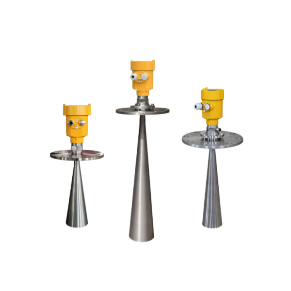
Radar Water Level Transmitter
Principle of Operation
The instrument’s antenna emits high-frequency microwave signals; these penetrate the air, reach the water surface and are reflected back to the instrument’s receiver. By precisely calculating the round-trip propagation time of the microwaves, the instrument determines the distance between the probe and the liquid surface.
After accounting for any installation height difference, it calculates the real-time water level value, which is processed and output as a 4–20 mA current signal; high-end models also support HART digital communication. These are categorised into two types: rod-type guided-wave radar and horn-type non-contact radar.
Advantages
1. Unaffected by mist, foam, temperature, dust or water viscosity, ensuring exceptional measurement stability
2. Minimal measurement dead zone, enabling precise detection even at low liquid levels
3. High measurement accuracy, down to the millimetre level, meeting the high-precision monitoring requirements of water conservancy and chemical engineering
4. Low signal attenuation over long distances with the 4–20 mA signal, making it suitable for long-distance monitoring of dams and large reservoirs
5. The non-contact version suffers no loss due to immersion and is resistant to corrosion and extreme temperatures
6. Stable operation is ensured even in sealed water tanks and vessels containing volatile water vapour
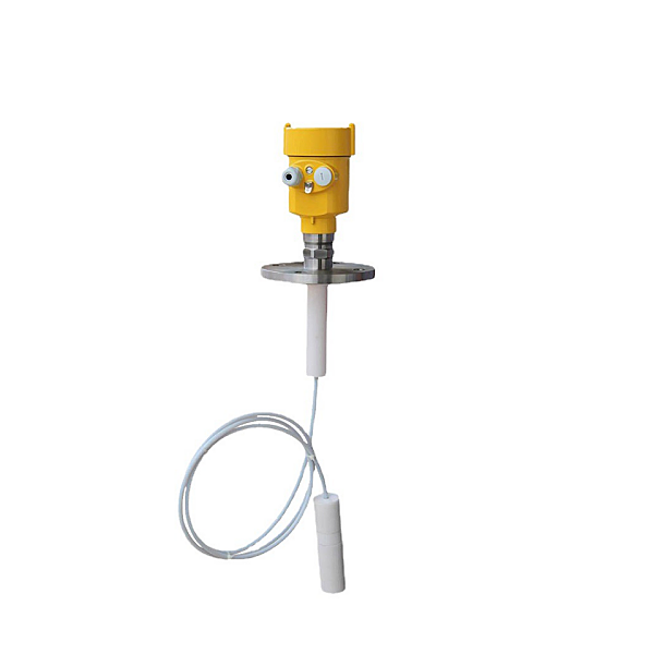
Magnetostrictive Water Level Transmitter
Principle of Operation
The main body of the level transmitter consists of a sealed measuring rod, inside which is a magnetostrictive waveguide wire; a magnetic float assembly is mounted on the exterior of the measuring rod and rises and falls in synchronisation with the water level.
The instrument generates excitation pulses that are transmitted along the waveguide wire; the interaction between the float’s magnetic field and the excitation pulse generates a magnetostrictive strain signal.
The circuit captures the time difference in signal propagation to calculate the float’s position, converting this into a linear 4–20 mA current signal output corresponding to the liquid level height.
Advantages
1. Measures accurately with solid linearity, and stays zeroed in without drifting over months of operation
2. Puts out a standard 4–20 mA signal, so it drops right into most industrial control setups
3. Tracks both water level and the oil-water interface at the same time, giving you two readings from one unit
4. Built with no internal rubbing parts, so wear stays low and the unit keeps running for years
5. Reacts quickly enough to catch even small level changes and feed that data back in real time
Advantages of 4–20 mA Signal Output
1. Excellent interference resistance.Current signals are less susceptible to industrial electromagnetic interference and line resistance; signal transmission remains stable over long distances without significant voltage drop distortion.
2. Supports long-distance cabling. Not restricted by cable voltage drop; standard shielded cable allows transmission over 100 metres without the need for additional signal compensation circuits.
3. Built-in cable fault diagnosis function. Unlike the 0 mA starting point of traditional signals, this solution adopts 4 mA as the minimum signal threshold. Once a circuit disconnection occurs, the loop current will fall to zero, allowing the control system to instantly detect and judge line failures.
4. Reduced field wiring expenses. Two-wire transmitters draw operating power directly from the signal loop. This design removes the need for dedicated power lines, greatly simplifying on-site wiring work and cutting overall installation costs.
5. Matches all common industrial communication norms. In field operations, 4mA represents the lower limit of the measuring span and 20mA marks the upper limit — a spec that the industry has stuck with for decades. Because pretty much everyone uses this standard, the device plugs right into most mainstream PLC units and local display meters without any headaches.
6. Simple signal conversion paired with stable linear output. The loop current output maintains a strictly linear match against real-time process variable readings captured on-site. This characteristic cuts down workload during program tuning and signal translation work, and also helps keep overall system measurement deviations to a minimum.
7. Multiple data acquisition devices can be connected in series.The circuit can simultaneously connect digital displays, controllers and other devices, allowing a single signal to be read by multiple devices.
8. High explosion-proof safety.With a maximum current of only 20mA and low power consumption, it can be used in flammable and explosive environments when paired with a safety barrier.
What is the difference between 4–20mA and 0–10mA signal outputs?
1. Fault detection capability
4–20 mA: The zero point is 4 mA; if a wire breaks, the current drops to 0 mA, so the controller can detect a circuit break directly and tell the difference between a missing signal and the measurement zero point.
0–10 mA: The zero point is 0 mA; both a broken wire and a measured value of zero show up as 0 mA, so there’s no way to tell whether it’s a fault or just a normal zero point.
2. Support for two-wire wiring layouts
4–20 mA Signals: The base 4 mA output delivers sufficient power to run sensor hardware. It fits perfectly with standard two-wire transmitter wiring layouts, which reduces total cable consumption and brings down field installation expenses.
0–10 mA Signals: This signal type begins at zero current output. It cannot supply steady power to field devices independently, meaning a four-wire configuration with dedicated power wiring is mandatory to supply operating power.
3. Standardisation and Universality
4–20 mA: As a well-established industrial universal specification, it boasts full compatibility with mainstream PLCs, transmitters and display meters. Field equipment replacement and upgrading can be completed without modifying any control programs.
0–10 mA: It is an obsolete and rarely adopted industrial standard. Most modern industrial control modules no longer offer native support for it, resulting in extremely poor equipment compatibility and interchangeability.
4. Measurement Range and Load Characteristics
When wired the same way, both signal types can handle voltage drop interference. That said, the 4–20 mA signal gives a wider measuring range and better signal resolution, so weak target signals don’t get drowned out by background noise.
The 0–10 mA current span, on the other hand, is much narrower, which means measurement deviations stand out more when picking up ultra-weak signals and hurts overall detection accuracy.
5. Explosion-Proof Applications
Mature safety barrier solutions are available for 4–20 mA, and it is widely used in explosion-proof chemical environments; explosion-proof accessories for 0–10 mA are scarce, and it is rarely used in hazardous areas.
Analogue Signals vs Digital Signals
I. Differences in Signal Definition
An analogue signal is an electrical signal that is continuous in both time and amplitude throughout its entire range; it can faithfully reproduce changes in physical quantities such as sound, temperature and light, and serves as a direct representation of the original signal.
A digital signal is a discrete, step-change signal that takes values only at fixed time points, typically in the two states of binary 0 and 1; it is a standardised signal obtained by sampling, quantising and encoding an analogue signal.
II. Differences in Waveform and Characteristics
The waveform of an analogue signal is a smooth, continuous curve with no abrupt breaks or jumps; its values can take any form, and changes are subtle and seamless.
A digital signal is a regular square wave, characterised by alternating high and low voltage levels; it has only two fixed states, with no intermediate values.
III. Differences in Interference Resistance and Transmission Quality
Analogue signals have poor resistance to interference; their transmission is easily affected by electromagnetic and noise interference, leading to distortion and attenuation. Noise cannot be eliminated; the further the signal is transmitted, the more severe the distortion becomes, making recovery difficult.
Digital signals have strong resistance to interference; minor interference does not affect the recognition of high and low levels, there is no accumulation of noise, and transmission is essentially distortion-free.
IV. Differences in Signal Processing and Storage Methods
Analogue signals can only undergo simple processing, such as amplification and filtering, via dedicated circuits; they offer low precision and poor flexibility, and cannot be stored or copied without loss of quality. Repeated copying results in the accumulation of noise and a deterioration in picture and sound quality.
Microchips and industrial computers handle digital signals with excellent precision. These signals can be saved permanently and duplicated countless times without signal distortion or quality drop-offs.
V. Transmission Methods & Matching Devices
Analog signals need their own dedicated signal lines to get around. Their transmission bandwidth is pretty limited and transfer efficiency is low, so they don’t work well for long-distance or large-data jobs. You mostly see them in older gear like old landline phones and analog TV sets.
Digital signals travel over fiber optic lines or wireless links. They come with large bandwidth, fast transfer rates and work with a wide range of hardware, which is why they’re everywhere in today’s mobile networks, data communication and digital audio/video equipment.
VI. Accuracy & Error Performance Contrast
Analog signals carry no quantization distortion and retain every subtle detail of the original signal. Even so, outside electromagnetic interference easily distorts them and triggers random reading errors, leading to unstable operation.
Digital signals bring small, manageable quantization errors and cannot capture every tiny nuance of raw signals. Still, outside environmental factors barely impact their readings, granting them superior overall precision and stable performance.
All things considered, 4–20 mA analog signals have remained the primary transmission standard for process monitoring in industrial automation for years.
Sino-Inst carries a complete lineup of level transmitters built with 4–20 mA output options. Our product portfolio covers hydrostatic submersible, ultrasonic, radar and magnetostrictive variants, catering to every common water monitoring scenario on the market.
Beyond level measurement gear, we also provide standard 4–20 mA pressure sensors and temperature transmitters. This full product suite lets facilities sync readouts from level, pressure, temperature and other process variables under one consistent signal format, streamlining overall system integration work.