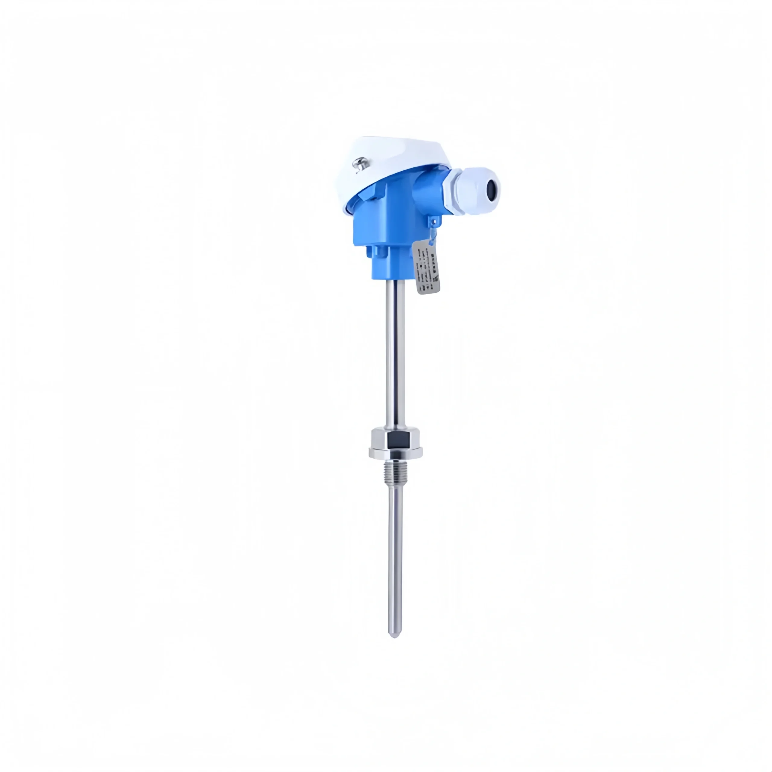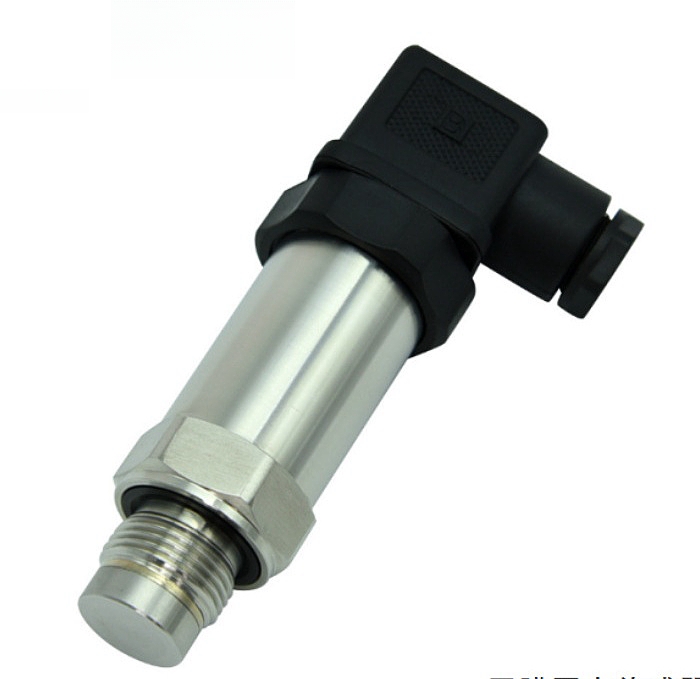
A temperature transmitter converts temperature signals into a standard electrical signal. It is primarily used to measure and control temperature parameters in industrial processes. A current transmitter converts the measured main circuit AC into a constant current loop standard signal and continuously transmits it to a receiving device.
Temperature transmitters use thermocouples and RTDs as temperature measuring elements. The output signal from the measuring element is sent to the transmitter module. After processing through circuits including voltage stabilization and filtering, operational amplification, nonlinearity correction, V/I conversion, constant current, and reverse protection, the signal is converted into an electronic signal output. The signal is linearly related to temperature.
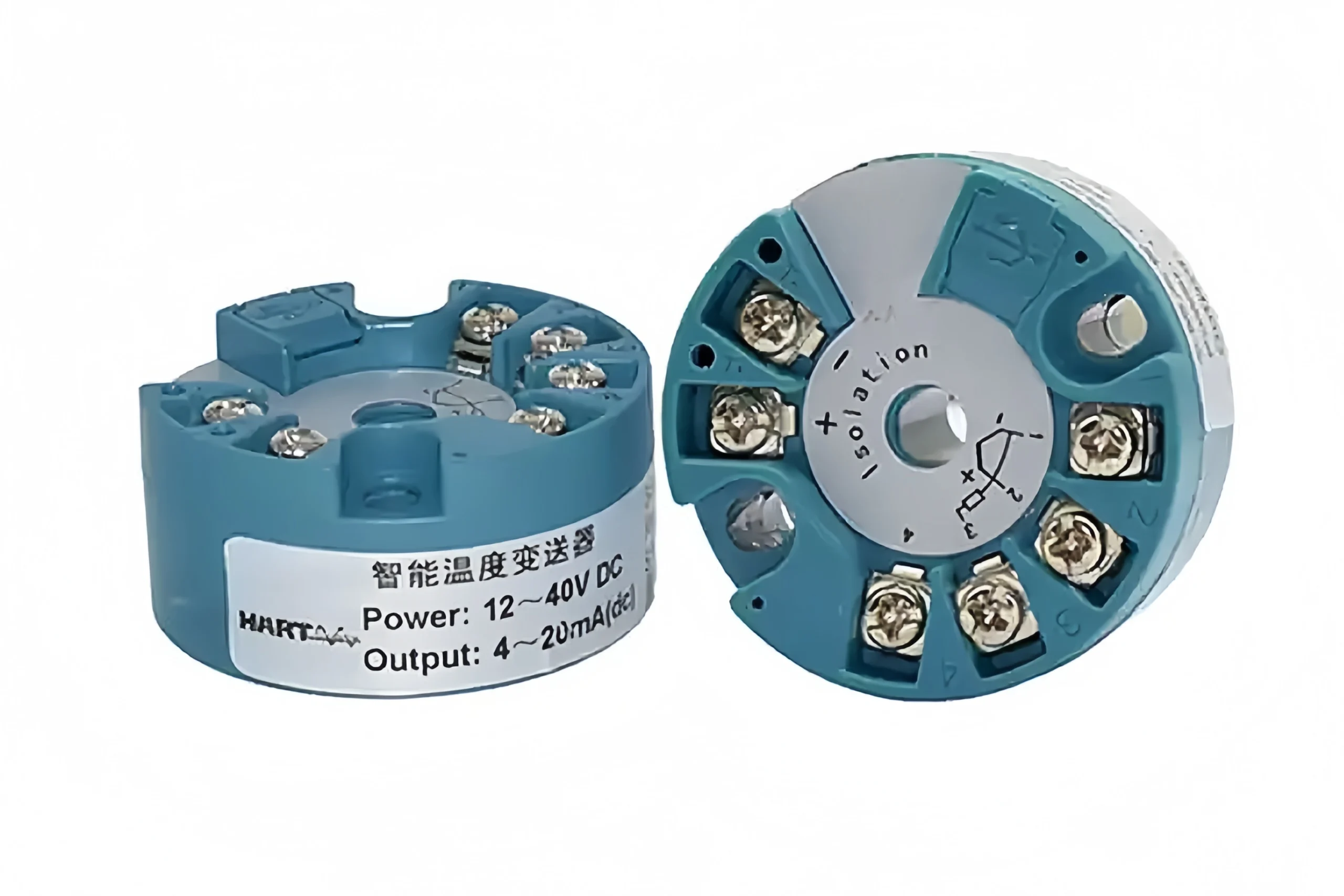
Temperature transmitters are mainly divided into thermocouple temperature transmitters and RTD temperature transmitters.
Thermocouple Temperature Transmitter
Principle of Operation
Thermocouples utilise the Seebeck thermoelectric effect, whereby two dissimilar metals form a closed circuit; a temperature difference between the two ends generates a faint thermoelectric potential.
The transmitter acquires this millivolt-level thermoelectric potential, performs cold-junction compensation, amplification and linearisation, and converts it into a standard 4–20 mA current output. The current value corresponds linearly to the measured temperature and is transmitted to a secondary control instrument.
Advantages
1. Wide temperature measurement range, covering temperatures from ultra-low to over 1,000 degrees, with superior adaptability to high-temperature operating conditions.
2. Compact probe size and low thermal mass result in fast temperature response, making it suitable for confined installation locations.
3. High-temperature resistance, shock and vibration resistance, and a robust structure make it suitable for high-temperature, vibrating environments such as boilers and heat treatment furnaces.
4. The low cost of the sensor itself means that large-scale deployment can effectively reduce the overall project cost.
Disadvantages
1. Measurement accuracy at low temperatures is relatively low; weak signals are prone to errors caused by line resistance and electromagnetic interference.
2. The thermoelectric potential is non-linear and relies on transmitter algorithms for correction; it is difficult to control deviations in the low-temperature range.
3. Cold-junction compensation is essential; significant fluctuations in ambient temperature can directly cause measurement drift.
4. Dedicated compensation leads are required; incorrect wiring or excessively long cables will increase measurement errors.
5. Measurement accuracy at room temperature is inferior to that of RTD (Resistance Temperature Detector) thermistors.
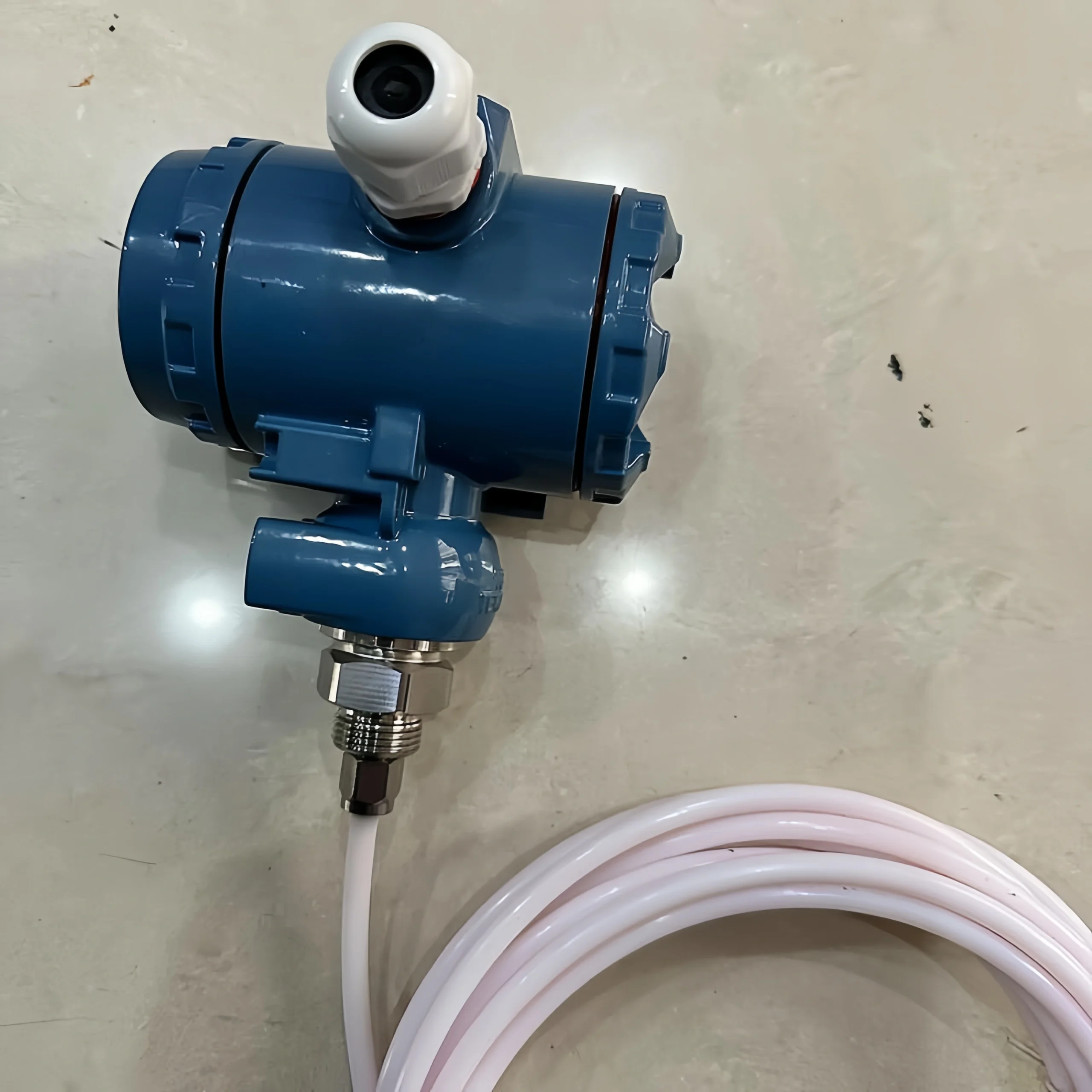
RTD Temperature Transmitter
Principle of Operation
Resistance temperature detectors (RTDs) measure temperature based on the property that the resistance of platinum increases in tandem with temperature; at 0°C, the resistance of a PT100 is 100 Ω.
The transmitter uses a Wheatstone bridge to measure changes in the RTD’s resistance; after compensating for lead resistance, it amplifies and conditions the signal, converting it into a linear 4–20 mA standard current for the stable transmission of temperature data over long distances.
Advantages
1. High measurement accuracy within the normal temperature range, with inherent good linearity and excellent measurement repeatability and stability.
2. No cold-junction compensation is required; changes in ambient temperature are unlikely to cause significant measurement drift, and commissioning and maintenance are straightforward.
3. Strong signal immunity to interference and a high signal-to-noise ratio, making it suitable for precision temperature control, clean piping systems and laboratory equipment.
4. The PT100 specification is universal, ensuring good compatibility with associated instruments and control systems, and facilitating the replacement of spare parts.
Disadvantages
1. The upper temperature limit is approximately 600°C; it cannot be used in ultra-high-temperature measurement scenarios such as smelting or high-temperature furnace chambers.
2. It has high thermal mass, resulting in response lag during sudden temperature changes; it is not suitable for rapid transient temperature measurement.
3. Lead resistance affects measurement accuracy; three-wire or four-wire configurations are preferred for long-distance wiring.
4. The internal platinum wire is prone to breakage due to severe vibration, resulting in a short service life in equipment subject to strong vibrations.
5. Prolonged exposure to high temperatures causes oxidation and drift in the platinum wire, reducing service life; procurement costs are higher than those of standard thermocouples.
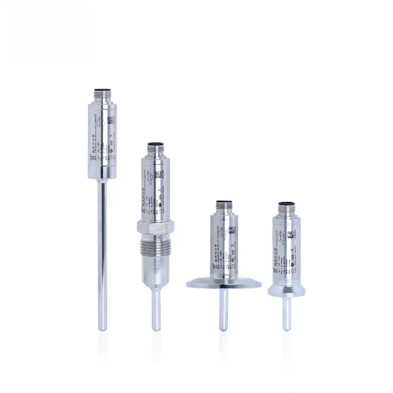

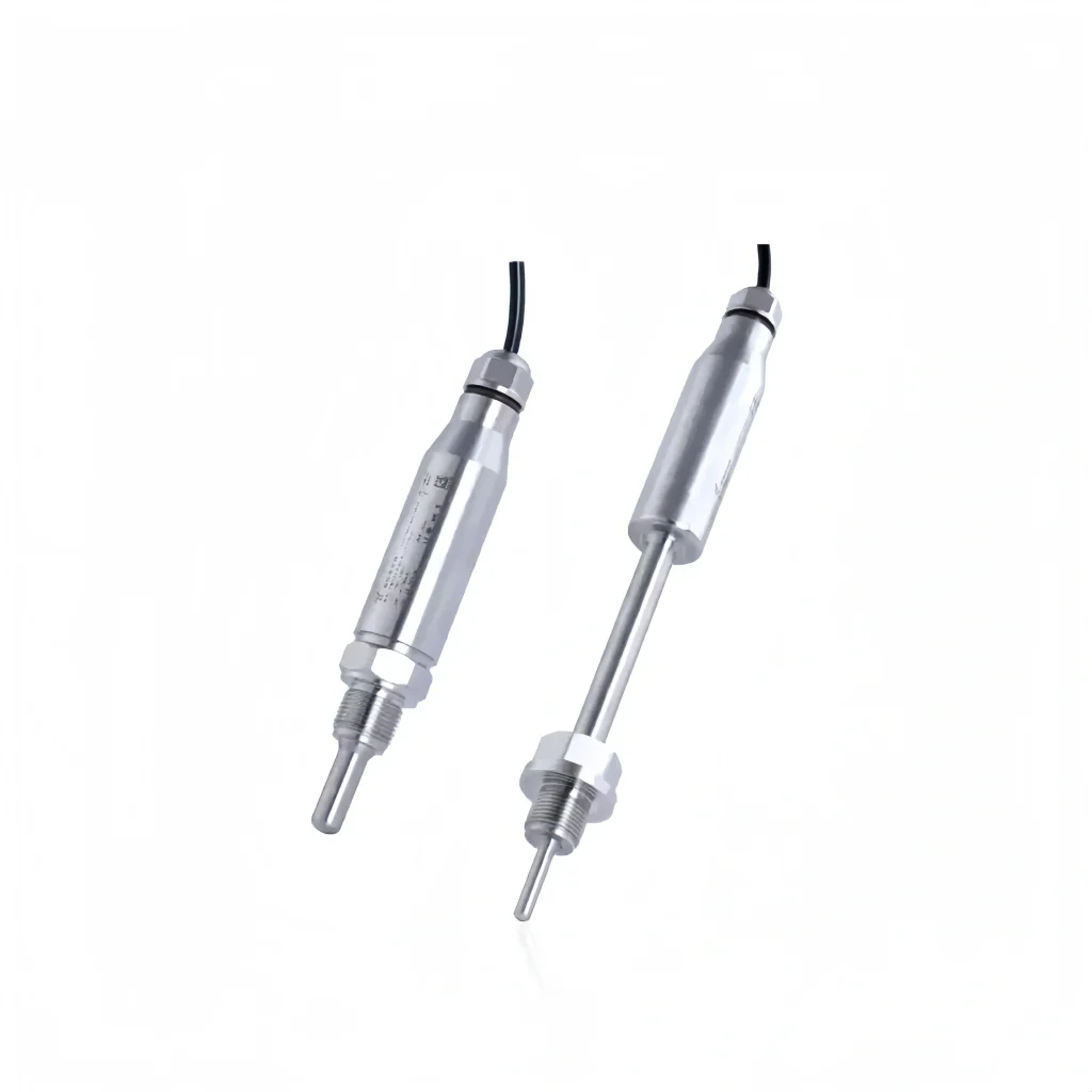
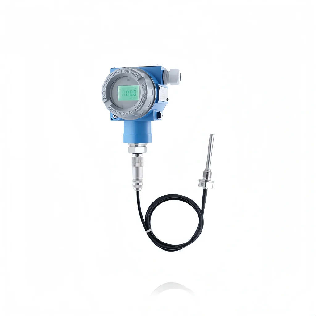
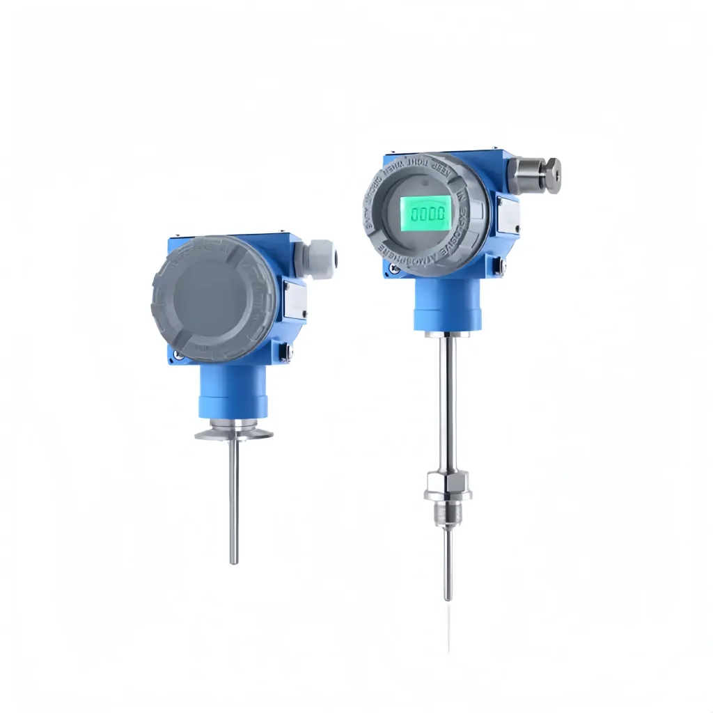
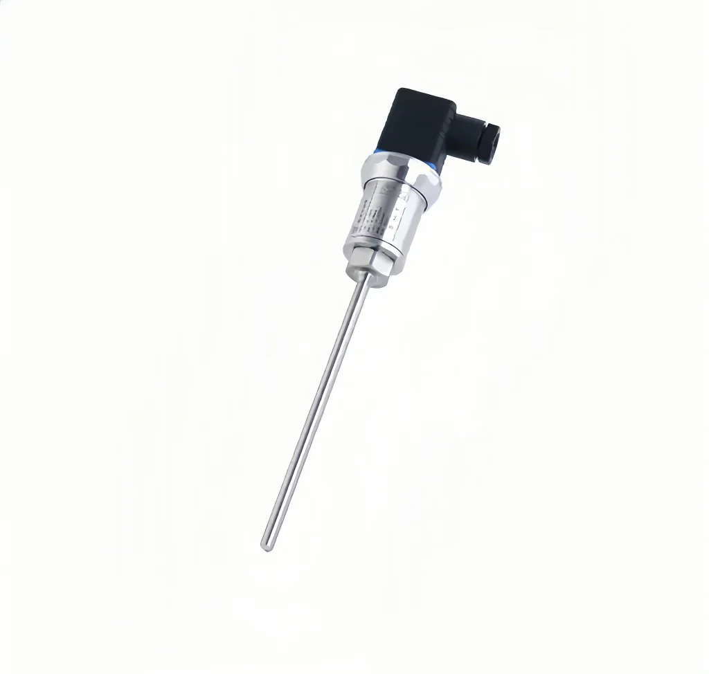
Temperature transmitter input signals come in two types: RTDs and thermocouples. The following is a detailed description:
RTD Input Signal
Based on the element structure, RTD input signals can be categorized as either wire-wound RTDs or thin-film RTDs. The following is a detailed introduction.
1. Wirewound RTD
This type of RTD has a small-diameter wire, most commonly platinum, wound into a coil placed within a ceramic/glass insulator. Extension wire is soldered to this platinum coil, which extends outside the insulator. Compared to thin-film sensors, this type of sensor is longer and more delicate. Wirewound RTDs offer good accuracy over a wider temperature range.
2. Thin-film RTD Element
Thin-film elements are made by depositing a very thin layer of resistive platinum metal onto a ceramic substrate. This film is then coated with epoxy or glass, which helps protect the deposited film and also serves as a strain relief for the external leads. This type of RTD performs better in vibration applications and for field temperature measurements.
Due to their versatility and cost-effectiveness, thin-film sensors are the most widely used sensor type. RTDs can also be differentiated based on the resistive element material. They are often referred to as Pt100, P1000, Ni120, Cu100, etc.
The letter indicates the element material, and the number indicates the resistance value at zero degrees Celsius. Therefore, a Pt100 element has a platinum resistance element and a resistance of 100Ω at 0°C. A Ni120 element has a nickel resistance element and a resistance of 120Ω at 0°C.
Thermocouple Input Signal
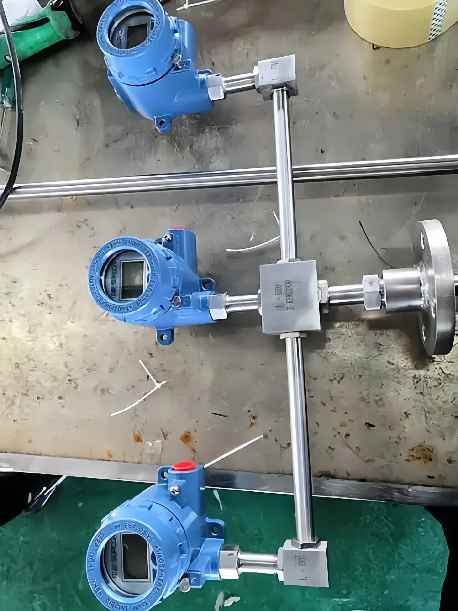
Thermocouple temperature transmitters (K, S, E, B, R, T, J, N, etc.) receive signals from field thermocouple sensors, process them, and convert them into a standard output signal. The signal is linearly proportional to temperature.
Common Thermocouples
1. Type K thermocouple: Made of nickel-chromium–nickel-silicon, with a temperature measurement range of –200 to 1,300 °C. It offers good value for money and excellent resistance to oxidation. As a general-purpose industrial model, it is suitable for routine temperature measurement in boilers and heat treatment processes.
2. Type S thermocouple: Made of platinum-rhodium 10–platinum, with a temperature range of 0–1,600 °C. It offers extremely high measurement accuracy and excellent stability, and is commonly used for high-temperature calibration and in precision kilns, though it is expensive.
3. Type B Thermocouple: Made of platinum-rhodium 30–platinum-rhodium 6, with a maximum temperature of 1,800 °C. It offers excellent high-temperature oxidation resistance and is suitable for ultra-high-temperature smelting applications; its low-temperature thermoelectric potential is extremely low, eliminating the need for cold-junction compensation.
4. Type E thermocouple: Made of nickel-chromium and copper-nickel, it has high sensitivity at low temperatures, with a measurement range of –200 to 800 °C. It is suitable for low-temperature and vacuum equipment, but is susceptible to corrosion by sulphurous gases.
5. Type J thermocouple: Iron–copper-nickel composition, with a temperature measurement range of –200 to 750 °C. It offers high sensitivity and is inexpensive, but cannot be used in high-temperature oxidising environments, as the iron wire is prone to rust.
6. Type T thermocouple: Copper–copper-nickel composition, with excellent low-temperature accuracy and a temperature measurement range of –200 to 350 °C. It is commonly used in low-temperature cold stores and for precision low-temperature measurements in laboratories.
Different thermocouples have different operating ambient temperatures. The following is a detailed introduction. For operating temperatures between 1300°C and 1600°C, B-type thermocouples are generally used when high accuracy is required.
- For operating temperatures between 1100°C and 1300°C, S-type and R-type thermocouples are generally used.
- For temperatures between 400°C and 1100°C, K-type and N-type thermocouples are generally used.
- For temperatures above 400°C, E-type and J-type thermocouples are generally used.
- For temperatures below 300°C and below negative temperatures, T-type thermocouples are generally used. At low temperatures, T-type thermocouples offer greater stability than other thermocouples.