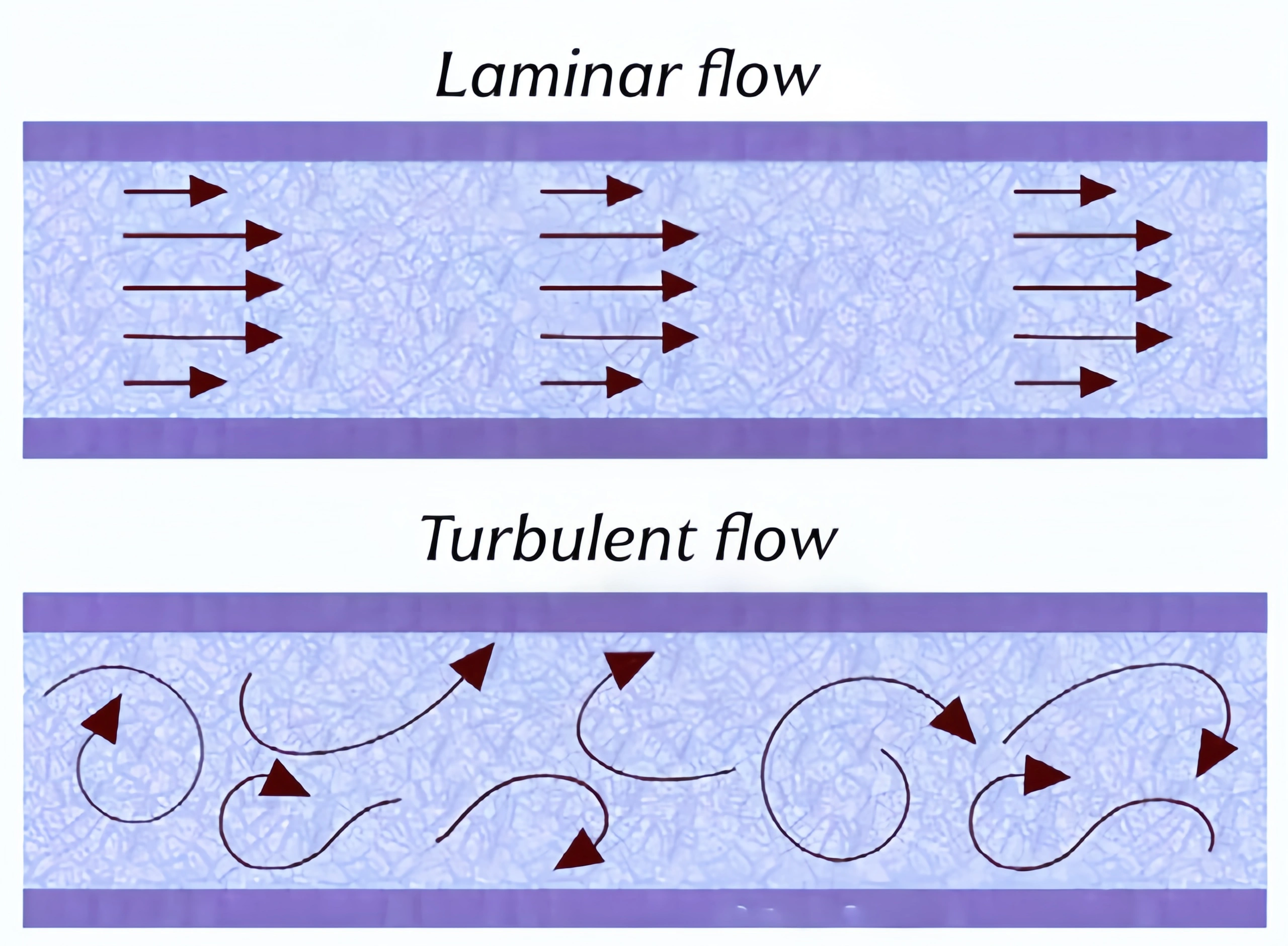
Laminar flow is a fundamental form of fluid flow in which particles within the fluid move steadily forward along parallel, well-defined streamlines. Interaction between fluid layers is limited to molecular diffusion, with no significant mixing of particles or vortical disturbances.
When the fluid velocity is low and the inertial forces are much smaller than the viscous forces, the flow typically exhibits laminar behavior. The velocity distribution across the cross-section of a laminar flow in a pipe follows a parabolic pattern, with the highest velocity at the center and the velocity approaching zero near the pipe wall.
Characteristics of laminar flow:
1. Fluid particles move in an orderly manner along parallel streamlines; different fluid layers do not mix with one another, and no random vortices are generated.
2. The flow is stable, and pressure loss is linearly proportional to the average fluid velocity.
3. The velocity distribution across the pipe cross-section follows a parabolic curve, with the highest velocity at the center of the pipe and the lowest velocity near the pipe wall.
4. The flow is primarily governed by viscous forces, with inertial forces having a relatively weak influence; it generally occurs under conditions of low flow velocity, small pipe diameters, or high-viscosity media.
5. The flow state remains steady, and neither velocity nor pressure exhibits erratic pulsations.
In laminar flow, the velocity distribution along a cross-section perpendicular to the flow direction follows a parabolic pattern. The velocity is highest at the center of the pipe. Near the pipe wall, the velocity gradually decreases, reaching zero. In laminar flow, the pressure decreases linearly along the pipe axis. Vertically, the pressure increases along the pipe wall. In aerodynamics, the characteristics of laminar flow must be considered in airfoil design, ship surface coatings, and high-speed train body design to reduce drag.
Turbulent flow is the most common form of fluid flow in engineering pipelines. When the fluid velocity increases and inertial forces far exceed viscous forces, fluid particles no longer move along regular, parallel streamlines.
Instead, numerous irregular vortices form, and fluid layers continuously mix and collide with one another, causing random fluctuations in velocity and pressure at any given moment.
In the vast majority of industrial fluid measurement scenarios, the medium inside the pipeline is in a turbulent state, which is also the flow condition that must be given primary consideration during flowmeter selection and calibration.
Turbulent flow is characterized by:
1. The fluid contains a large number of vortices of varying sizes that are constantly forming and dissipating; the motion of fluid particles is chaotic, and adjacent fluid layers are thoroughly mixed.
2. The velocity distribution across the pipe cross-section is relatively flat; compared to the parabolic distribution of laminar flow, it is more uniform, though the velocity gradient near the pipe wall is significant.
3. Pressure loss in the pipeline exhibits a nonlinear relationship with flow velocity; as flow velocity increases, the rate of pressure loss growth accelerates significantly.
4. The flow is accompanied by continuous, random fluctuations in velocity and pressure; signal fluctuations are common and directly affect the measurement stability of flow sensors.
5. The flow is dominated by inertial forces and is commonly observed under conditions of high flow velocity, large pipe diameters, and low-viscosity media; it is the predominant flow state in industrial pipelines.
In turbulent flow, the velocity distribution along a cross-section perpendicular to the flow direction is uniform. At the center of the pipe, the velocity is similar to that near the pipe wall. In turbulent flow, the pressure decreases linearly along the pipe axis. Vertically, the pressure increases along the pipe wall. At the same time, turbulent flow exhibits pressure fluctuations. In areas such as burner design, chemical reactors, and hydroelectric power plants, we need to consider the characteristics of turbulent flow to improve production efficiency.

Both gas and liquid flows can be classified as laminar or turbulent. Laminar flow is a stable state of fluid flow characterized by parallel streamlines, smooth flow, and no turbulence. Turbulent flow is an unstable state of fluid flow characterized by turbulence, vortices, and velocity fluctuations.
Different forms of particle motion: In laminar flow, fluid particles move in an orderly manner along parallel streamlines, and the fluid layers do not mix with one another; in turbulent flow, there are numerous disordered vortices, particles move chaotically, and the fluid layers continuously collide and mix.
Differences in Dominant Forces: Laminar flow is dominated by viscous forces, with inertial forces playing a minor role; turbulent flow is dominated by inertial forces, with viscous forces acting only within a thin layer adjacent to the pipe wall.
Differences in Cross-Sectional Velocity Distribution: In laminar flow, the velocity across the pipe cross-section follows a standard parabolic distribution, with the highest velocity at the center of the pipe; in turbulent flow, the velocity distribution is flatter and more uniform, with a rapid decrease in velocity only in the region near the pipe wall.
Different pressure loss patterns: Pressure loss in laminar flow is linearly proportional to the average fluid velocity; in turbulent flow, pressure loss follows a nonlinear exponential relationship with velocity, and the pressure drop increases more rapidly as velocity rises.
Different flow stability: Laminar flow is steady, with no random fluctuations in velocity or pressure; turbulent flow inherently involves continuous fluctuations in pressure and velocity, which can easily cause oscillations in flow measurement signals.
Different operating conditions: Laminar flow is commonly found in conditions involving low flow velocities, small pipe diameters, and high-viscosity media; turbulent flow occurs primarily in pipelines with high flow velocities, large pipe diameters, and low-viscosity media, and is also the most common flow state in industrial measurement.
Different Impacts on Flow Measurement: Some flow meters exhibit significant deviations in their measurement coefficients under laminar versus turbulent conditions. Turbulent pulsations can easily introduce measurement noise, while laminar flow requires careful consideration of measurement errors caused by velocity distribution.
The Reynolds number is a vital feature used to distinguish laminar flow from turbulent flow. The specific numerical values for these classifications were introduced at the beginning of this article. When selecting turbine and vortex flow meters, we should consider the Reynolds number of the fluid. There are formulas for the Reynolds number.
The Reynolds number is used in fluid mechanics to describe the state of fluid motion. British physicist Osborne Reynolds first proposed it.
The Reynolds number is calculated as: Re = ρvL/μ
where
ρ is the fluid density,
v is the fluid velocity,
L is the characteristic length (such as the pipe diameter), and
μ is the fluid’s dynamic viscosity.
The Reynolds number is widely used in various fields. It includes fluid mechanics, aerodynamics, naval architecture, and thermal engineering. By analyzing the Reynolds number, we can predict the flow state and performance of fluids under different operating conditions.
The ratio between internal forces and viscous forces can predict the likelihood of turbulence. The equation for the Reynolds number can be expressed as follows:
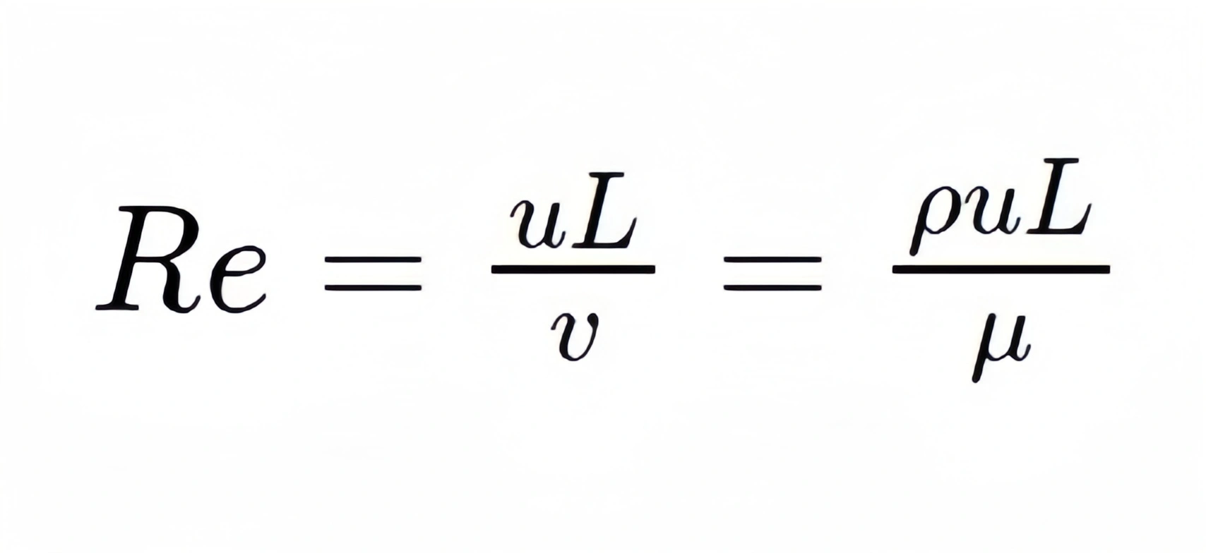
ρ = fluid density (kg/m³)
μ = flow velocity (m/s)
L = characteristic dimension or characteristic length, primarily pipe diameter, hydraulic diameter, equivalent diameter, or airfoil chord length (m)
μ = dynamic viscosity of the fluid (Pa·s)
v = kinematic viscosity (m2/s)
Reynolds’ research showed that pipe flows with low Reynolds numbers remain laminar. This is because they lack sufficient energy (in the form of inertial forces) to transform any instabilities in the fluid motion into flow perpendicular to the mean flow direction. As the fluid velocity or density increases relative to the viscosity, turbulence becomes more likely to develop.
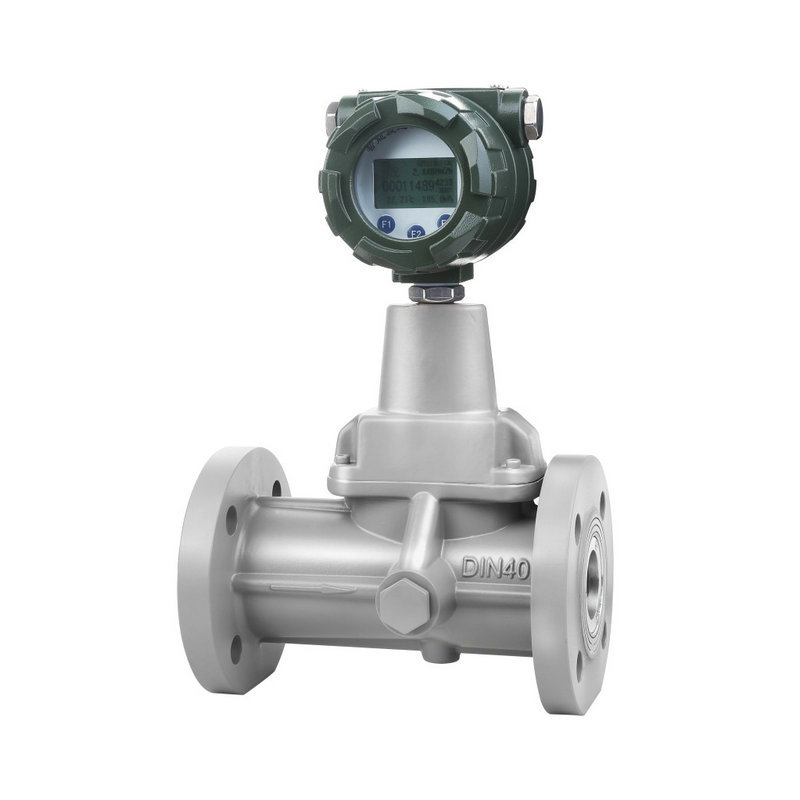
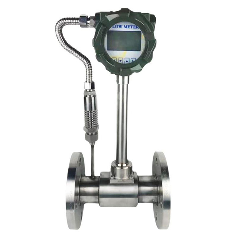
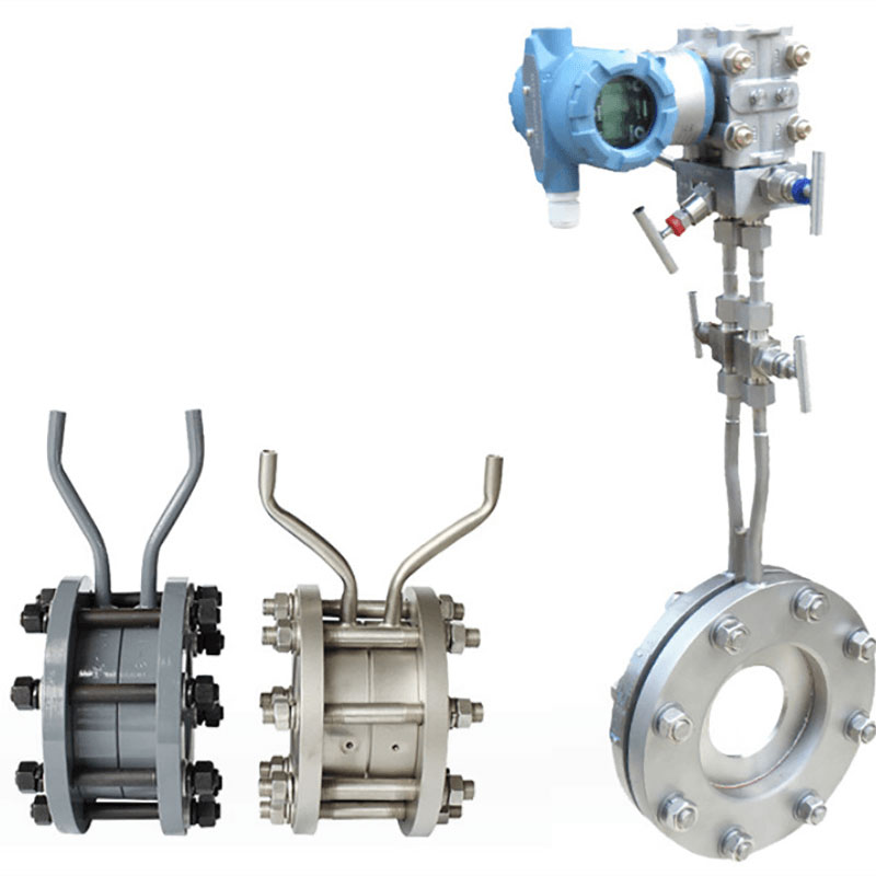
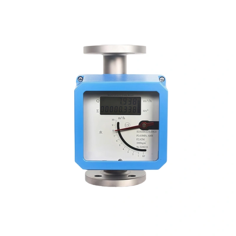
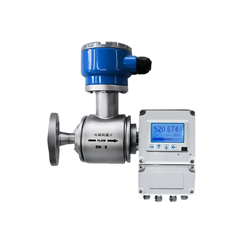
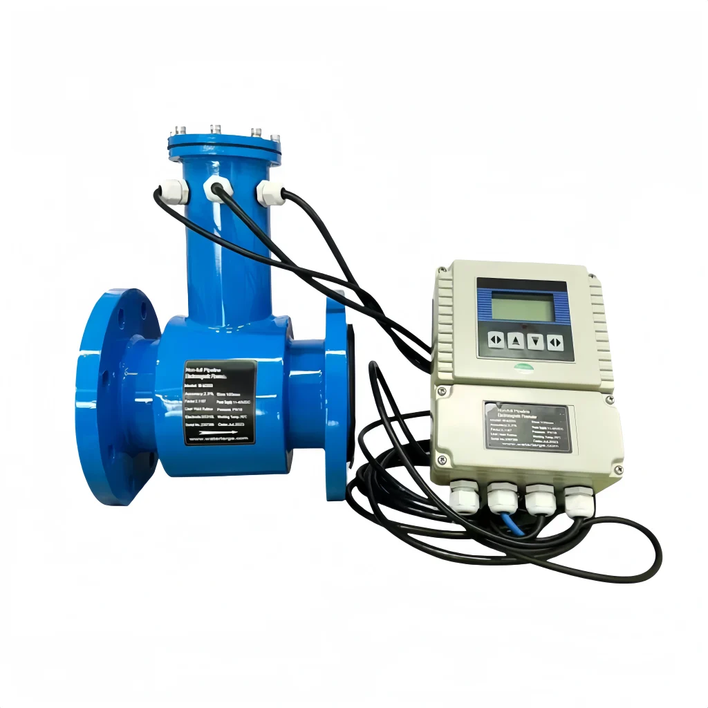
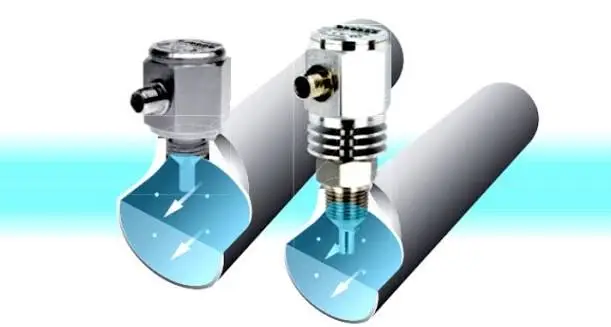
The extent to which turbulence affects a flow meter depends on the type of flow meter. If you are using a thermal flow meter based on the “bypass” principle, the main flow passes through the throttling element. While a small portion passes through the sensor. Turbulence can be caused by (excessive) restrictions in devices such as valves or adapters, as well as by the high flow velocity of the medium being used. This effect is called the “turbulence effect.” With each obstruction, the airflow is disrupted and the gas velocity changes. To address turbulence, we need to correctly dimension the pipe installation to ensure turbulence is reduced.
The ratio between the two flow rates is determined by the pressure drop across the sensor and the resistance in laminar flow. Turbulence can disrupt this ratio. Bypass sensor instruments are often used for very precise measurements. And turbulence can significantly affect the results. Thermal flow meters based on the “bypass” principle perform best under laminar flow conditions.
Turbulence can cause errors in flow measurement. Turbulent flow conditions affect different types of flowmeters. Vortex flow meters can disrupt vortex formation when bubbles or impurities are present. It leads to measurement errors. Although electromagnetic flow meters are well adapted to turbulent flow, severe turbulence can still affect their measurement accuracy.
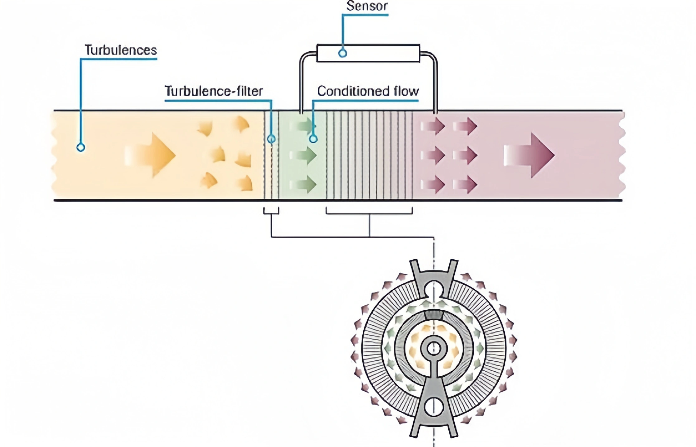
Laminar flow refers to the laminar flow of fluid in a pipe. In this state, the fluid flows without noticeable turbulence or vortices. Laminar flow is not always present. It is often limited to low flow velocities, low fluid viscosities, and narrow channels. Whether designing water or air pipes or evaluating the flow properties of industrial fluids, laminar flow is crucial. Maintaining laminar flow significantly improves overall efficiency in many industrial applications. such as chemical, pharmaceutical, and even transportation.
Calculating Flow in Laminar Flow
a) Flow Formula: Under laminar flow, the volumetric flow rate (Q) of a fluid can be calculated by multiplying the flow velocity (V) by the cross-sectional area of the pipe (A).
That is, Q = V x A.
Read More about: Flow Rate and Pressure Relationship Formula
b) Relationship between Flow Velocity and Pressure Drop: Under laminar flow, the volumetric flow rate of a fluid exhibits a linear relationship with the pressure drop across the pipe (AP). This relationship is based on the Hagen-Poiseuille law, which states that for laminar flow in an incompressible fluid within a circular pipe. The volumetric flow rate is linearly related to the pressure drop, given constant parameters. such as temperature and pipe diameter.
c) Flow Correction: To obtain standard volumetric and mass flow rates, the calculated volumetric flow rate must be corrected for pressure and temperature. Because the density of the fluid is affected by pressure and temperature. These corrections ensure the accuracy of the measurement results.