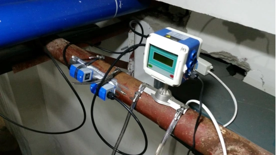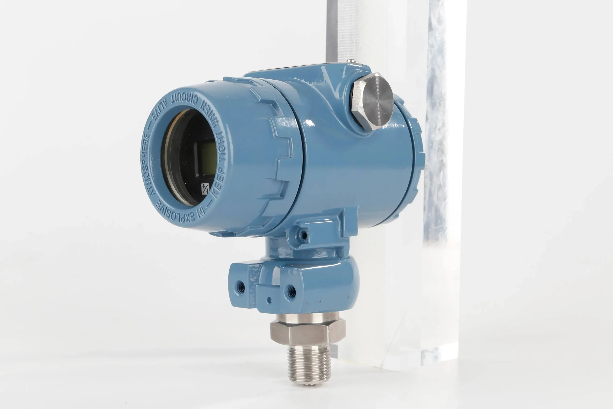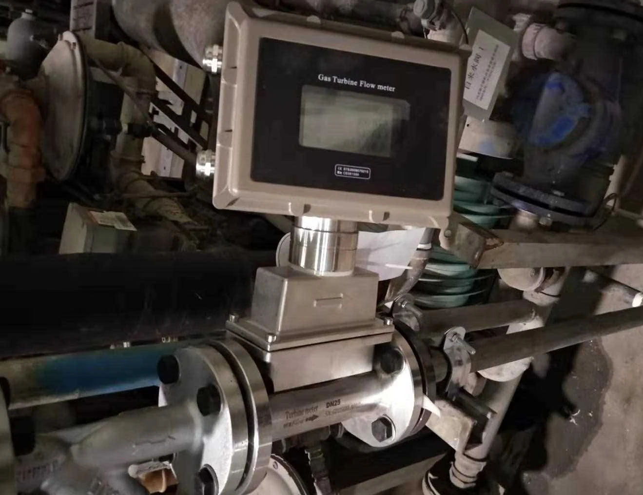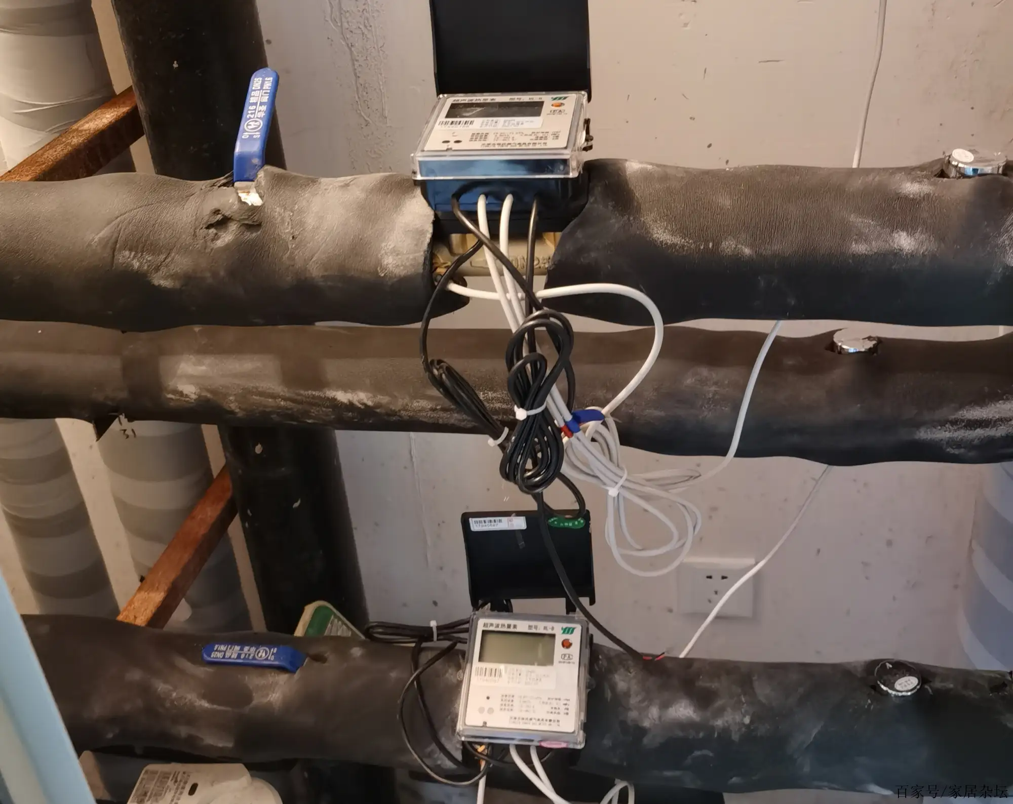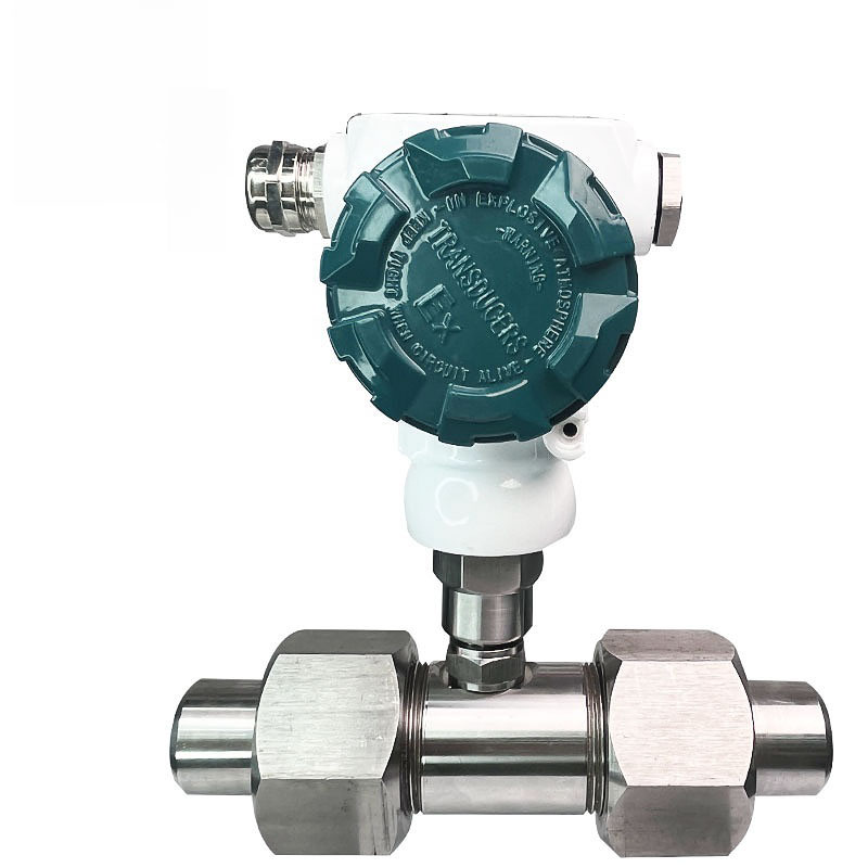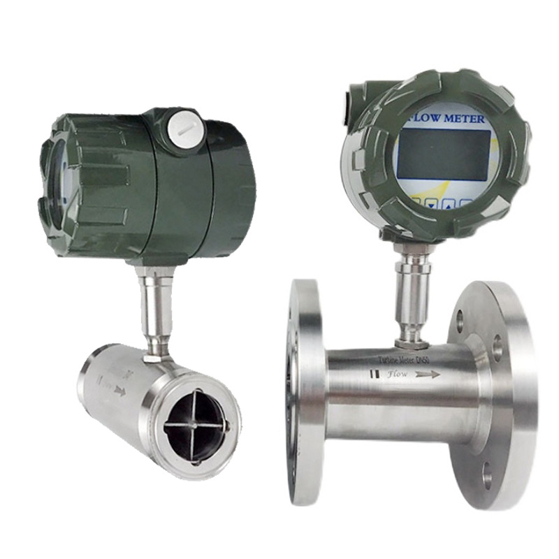
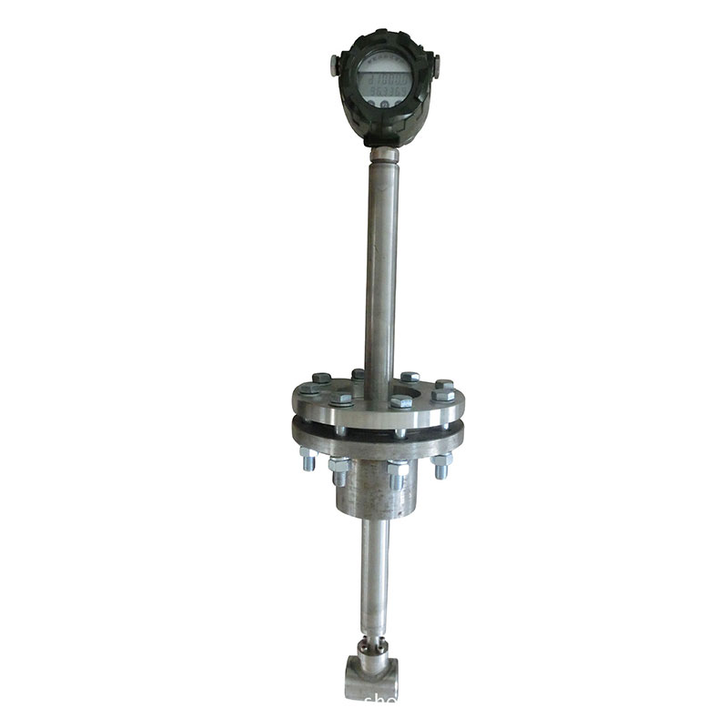
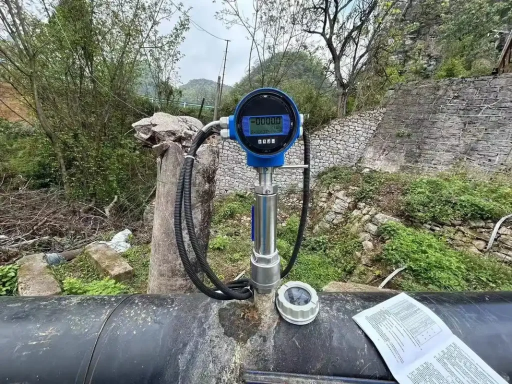
The insertion turbine flow meter is an online flow measurement instrument that detects fluid velocity and calculates flow rate by inserting a sensor probe into the pipeline. It’s perfect for measuring water, petroleum, chemical liquids and other stuff in big pipes. It’s easy to install, cheap to maintain and it doesn’t lose much pressure. It’s perfect for situations where you can’t stop production to install it..
Working Principle
The operating principle of the insertion turbine flowmeter involves fluid flowing through the sensor housing. Because the blades of the turbine wheel are angled compared to the direction of the flow, the fluid’s impact makes the blades spin. The blades can rotate because they’ve got rid of the friction torque and fluid resistance. Once you’ve got the torque equilibrium sorted, the rotational speed will stabilise. There’s a bit of a catch, but in certain situations, the rotational speed is directly linked to the fluid velocity.
As the blades possess magnetic properties, they operate within the magnetic field of the signal detector. As the blades rotate, they cut through the magnetic field lines, periodically altering the magnetic flux through the coil. This induces electrical pulse signals across the coil terminals. These signals are made stronger and changed by an amplifier, which makes them into continuous rectangular pulse waves of a known strength. These signals can be sent to a display instrument, showing the current and total volume of the fluid.
Structural Characteristics of Insertion Turbine Flow Meters
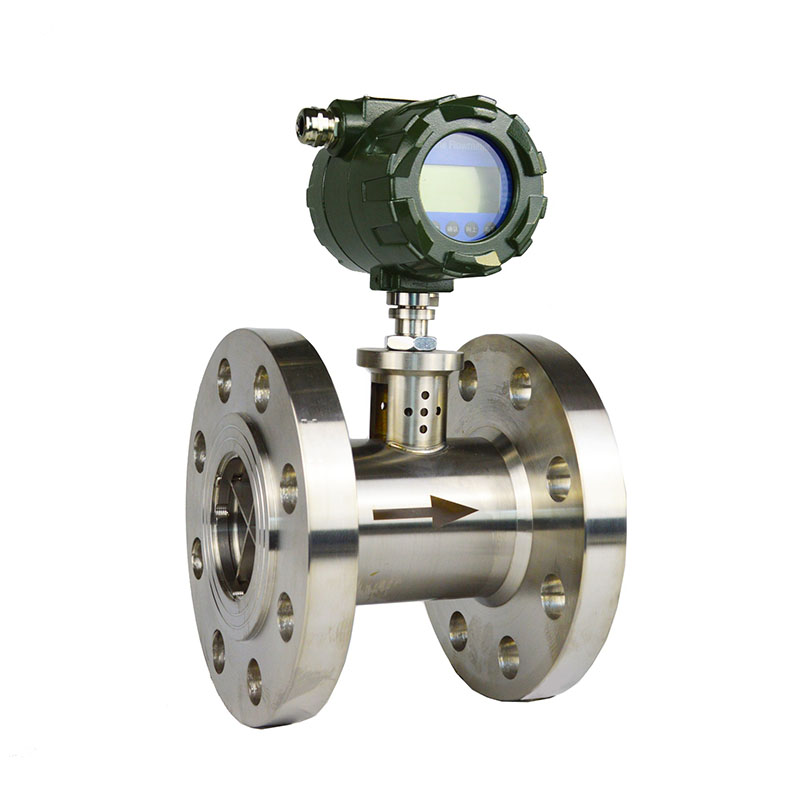
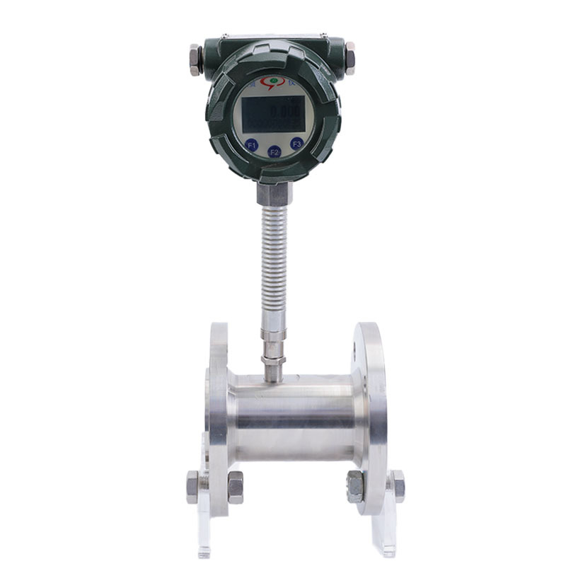
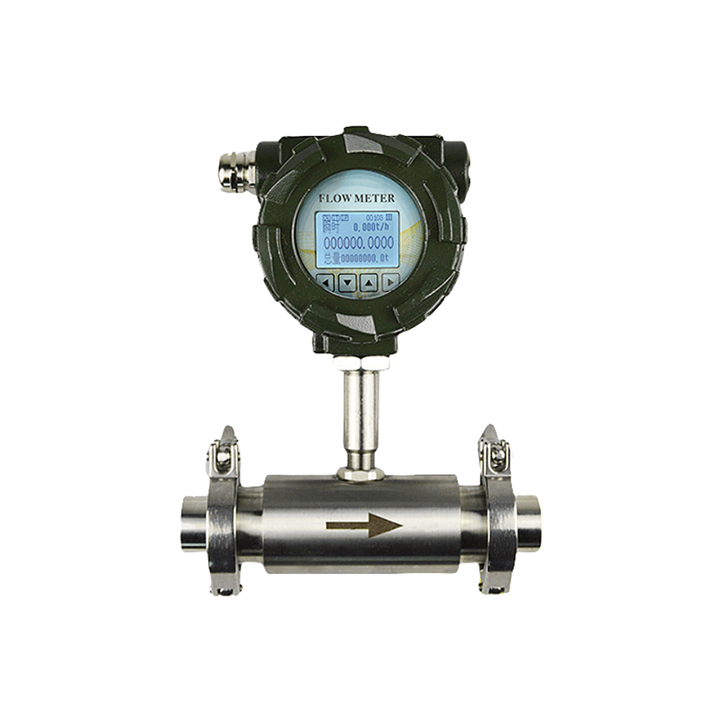
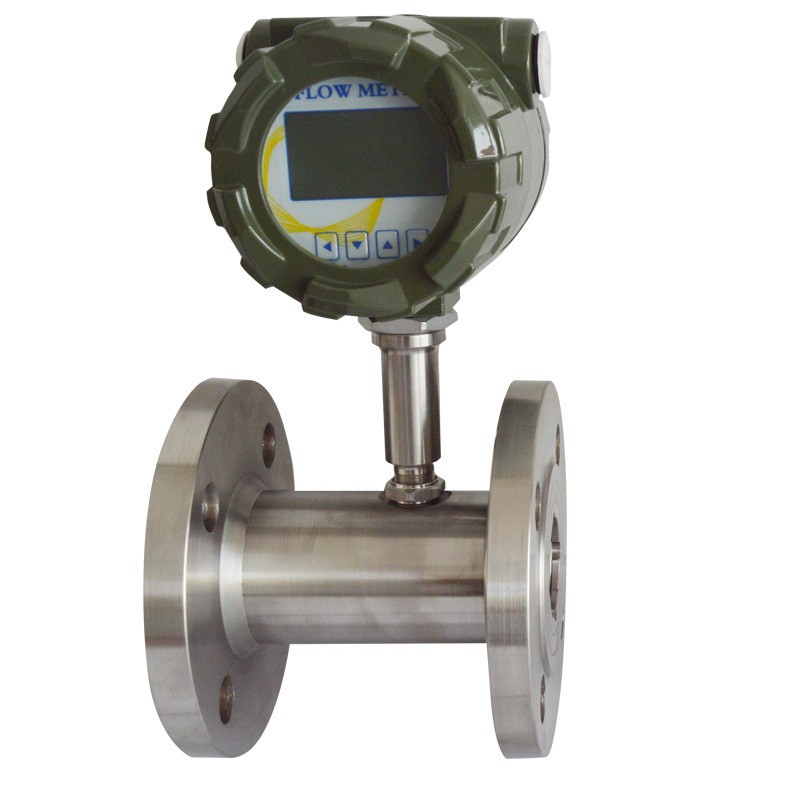
Insertion turbine flow meters primarily comprise turbine rotors, bearing systems, flow sensors, and casings. Each component plays a crucial role in the measurement process.
Turbine Rotor
The turbine rotor is the most important part of insertion turbine flow meters, and the way it’s shaped and designed has a big impact on how well the meter works. It’s usually made from lightweight but strong materials, and it can keep a steady rotational speed even when it’s moving really fast through high-velocity fluid flows. As the liquid goes through the turbine rotor, it makes it spin because of fluid dynamic forces, and the faster the flow rate, the faster it spins.
Bearing System
The bearing system makes sure the turbine rotor can rotate smoothly. Modern insertion turbine flow meters use high-precision bearing materials like ceramics or graphite, which really reduce friction and make them last longer.
Flow Sensor
The flow sensor is typically mounted on the turbine rotor shaft to detect the rotor’s rotational speed and convert it into an electrical signal that can be read. This signal is directly related to the fluid flow rate, so users get highly precise flow data after some signal processing.
Housing
The housing protects the internal components from outside influences and makes sure that the fluid can flow along a steady path without much resistance. The materials used for housing are usually metals or plastics that don’t rust, and they’re designed to handle whatever conditions they might be used in.
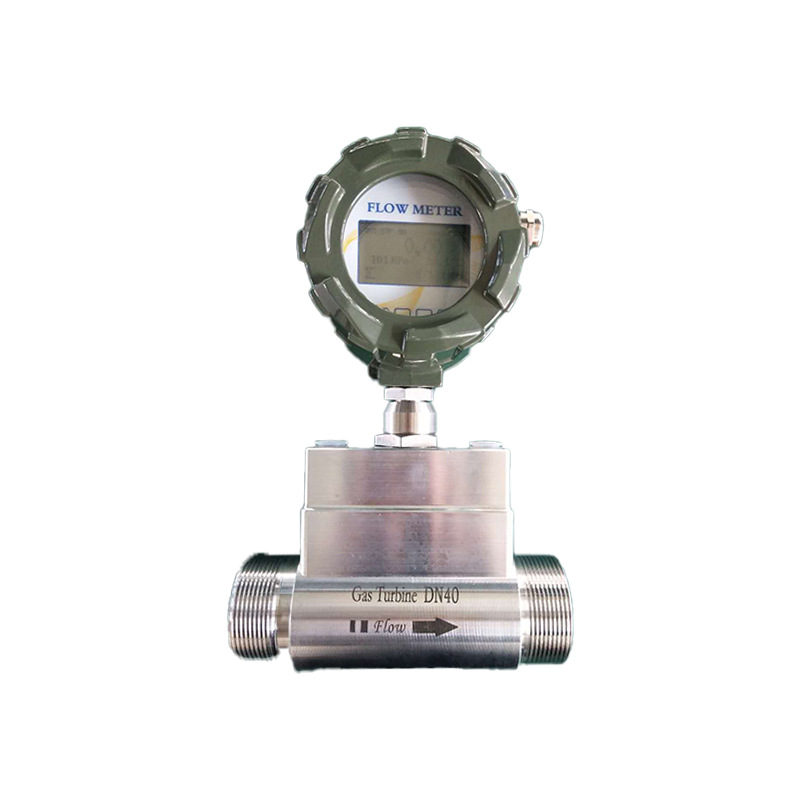
Advantages of Insertion Turbine Flow Meters
1. Flexible installation with insertion design
Requires no pipe cutting; sensors are inserted into pipelines via flange or threaded connections, making them suitable for flow monitoring in large-diameter pipes. Low construction costs, pressurised installation possible, minimising production downtime.
2. High Accuracy and Wide Range
It’s pretty accurate too, with a range of ±0.5% to ±1%, and it’s got a wide turndown ratio that covers all flow rates, from low (like night-time water supply) to high (like peak usage) in water treatment systems.
3. Strong Interference Resistance
Digital signal processing technology safeguards against electromagnetic interference and pipeline vibration, making it suitable for complex environments (e.g., near pumping stations or motors).
4. Low maintenance and extended service life
Turbine sensors feature no mechanical wear components, resulting in low failure rates. The insertion design facilitates routine cleaning or sensor replacement. Some models use stainless steel or materials that don’t rust, which makes them great for dealing with corrosive stuff.
Differences between Insertion Turbine Flow Meters and In-Line Turbine Flow Meters
Installation Method: Insertion turbine flow meters can be installed without having to stop the pipe, because the sensor probe goes straight into the pipe interior. In-line turbine flow meters are installed using full-bore straight-through set-up, which means you have to interrupt the pipe section to integrate the entire flow meter into the pipeline as a single unit.
Suitable Pipe Diameters: Insertion meters are mostly used for large diameters, usually from DN80 to DN3000, but some models can handle bigger sizes too. In-line meters are usually used for small to medium diameters, typically fitting DN10 to DN200. Customising for large diameters incurs extremely high costs and offers limited practicality.
Differences in flow conditions: Insertion-type meters measure only the local flow field around the probe, making results highly susceptible to velocity distribution within the pipe. In-line meters enable the medium to flow fully through the measuring chamber, ensuring a stable flow field. The measurement area covers the entire flow cross-section of the pipe, minimising the impact of velocity distribution.
Differences in measurement accuracy: Insertion-type devices offer relatively lower accuracy, typically ranging from ±1.0%R to ±2.5%R, with high-precision models achieving ±0.5%R. In-line devices provide higher accuracy, commonly ranging from ±0.2%R to ±1.0%R, with calibrated versions reaching ±0.15%R, meeting metrological requirements.
Pressure loss differs: Insertion-type meters exhibit minimal pressure loss, with only negligible obstruction from the probe itself. In-line meters incur relatively greater pressure loss as the medium traverses the flow meter’s internal flow chamber and turbine assembly, generating some resistance.
Differences in manufacturing costs: Insertion-type units offer lower per-unit costs, with particularly pronounced cost advantages in large-diameter applications. In-line units present moderate costs for small to medium diameters; however, as pipe diameter increases, customisation costs for valve bodies, turbine assemblies, and other components rise significantly, substantially diminishing cost-effectiveness.
Installation costs differ: Insertion meters require no pipeline interruption, enabling pressurised installation through drilling. This results in shorter project durations and lower labour costs. In-line meters necessitate pipeline shutdown for welding or flanging connections, leading to extended project timelines and higher labour expenses.
Maintenance complexity varies: Insertion meters are easy to maintain, as the probe can be removed for calibration or replacement without shutting down the pipeline. This makes maintenance straightforward and cost-effective. In-line flow meters need a lot of maintenance, which involves taking the whole meter apart. This means you have to shut down the pipeline, and it costs more to calibrate and transport the meters.
Different straight pipe section requirements: Insertion flow meters demand higher straight pipe sections, typically requiring 30D upstream and 10D downstream, with flow conditioners sometimes needed for optimisation; in-line flow meters have lower requirements, generally needing only 10D upstream and 5D downstream, as their internal flow guides already optimise the flow field.
Medium compatibility differs: Insertion-type meters are better suited for clean, single-phase, high-flow media such as circulating water, low-pressure gas, and industrial process water. In-line meters are better for clean, single-phase media that needs high accuracy, like refined petroleum products, chemical reagents and light oils.
Applications of Insertion Turbine Flow Meters
1. Municipal Water Supply and Drainage:It’s perfect for large-diameter mains in water supply and sewage networks, making it easy to track water flow and monitor pipeline pressure. You can install it under pressure without messing up the water supply or drainage.
2. Industrial Circulating Water:Designed for cooling and process circulation pipelines in steelworks, chemical plants and similar facilities, it ensures they can be used at all times and is easy to maintain.
3. Metallurgy and Power Generation:Employed for high-flow medium measurement in metallurgical equipment cooling water and power plant circulating water systems, ensuring safe equipment operation.
4. Low-Pressure Gas:Its large diameter and low pressure make it ideal for gas networks, as it allows you to monitor the flow without any service interruptions or modifications, and it barely causes any pressure loss.
5. Other Applications:This includes things like central air conditioning, cooling water and district heating, as well as low-pressure hot water systems. These systems monitor water flow and control costs.
Installation Considerations for Insertion-Type Flow Meters
1. Select a location where the pipe is fully filled. For horizontal pipes, install the meter on the side to prevent sediment accumulation at the bottom; for vertical pipes, prioritise sections where the medium flows upwards to eliminate half-pipe and air-lock conditions.
2. Ensure sufficient straight pipe sections: ≥10 times the pipe diameter upstream and ≥5 times the pipe diameter downstream; flow straighteners may be installed near flow-disrupting components to compensate for the flow field.
3. Keep the instrument away from sources of interference such as vibrations, variable frequency drives and high-power motors; explosion-proof instruments must comply with the site’s explosion-proof rating.
4. Depressurise and drain the pipeline before cutting an opening; ensure concentricity when welding the base. For non-metallic pipes, use a clamp-type base and clear any internal welding slag.
5. Control the insertion depth in accordance with the manufacturer’s requirements; align the probe’s sensing centre with the flow velocity zone in the pipeline, and ensure the probe rod faces the direction of fluid flow.
6. Select seals according to operating conditions and tighten evenly; for bases fitted with ball valves, close the ball valve before inserting or removing the probe to prevent leakage.
7. Carry out a leak test after installation to ensure the probe is securely fixed; lay the shielded cable separately and ensure it is reliably earthed, then complete the instrument parameter settings.
8. Allow sufficient space for maintenance; where the medium contains solid or fibrous impurities, increase the frequency of regular inspections and maintenance.
FAQ
Can turbine flow meters measure media containing impurities or bubbles?
Turbine flow meters aren’t the best choice for measuring media with impurities or bubbles. These meters rely on fluid flow to power the turbines, so any impurities can wear down the blades and bearings, which can mess up the measurements, shorten the lifespan, or even stop the meters from working.
Bubbles mess up the continuity of the fluid, which leads to signal distortion and inaccurate data. Should the medium contain minor impurities or bubbles, pre-treatment via upstream filters and degassers is feasible. Where impurities or bubbles are excessive, replacing the instrument with a suitable alternative is advised.
What are the common calibration methods for insertion turbine flowmeters? What scenarios suit each?
The core methods comprise on-site online calibration and offline disassembly calibration, catering to different production conditions and aligning with the core advantage of insertion-type flowmeters: no pipeline shutdown required.
On-site online calibration: Just do it straight on the pipeline, no need to take the probe apart. You can compare it to high-precision standard meters or portable calibrators. It’s perfect for when you can’t shut down the pipeline, and it’s really easy to use. You can keep production going without any problems, and it’s super quick to fix any mistakes in the measurements.
Offline disassembly calibration: The measuring probe is removed separately and tested on a standard calibration rig, which makes it more accurate. This is great for planned factory shutdowns or maintenance, or when online calibration shows errors that are too high and need precise calibration.
What are the advantages of turbine flowmeters compared to other flowmeters (such as vortex and electromagnetic types)?
Compared to common flowmeters like vortex and electromagnetic types, turbine flowmeters offer distinct advantages, with different turbine flowmeter variants adaptable to diverse application requirements.
Firstly, they offer rapid response times. As fluid passes through the turbine, it makes it spin quickly in response to changes in how fast the fluid is flowing. This means that there is only a short delay in getting the signal. This makes them perfect for use in situations where the flow of fluid changes a lot, as they can provide immediate feedback on these changes.
Secondly, they’re really accurate. Pipeline-type turbine flowmeters usually achieve accuracy within ±0.2%R to ±1.0%R, with calibrated models reaching ±0.15%R – which is significantly better than many standard vortex flowmeters. While insertion-type models are slightly less accurate (±1.0%R to ±2.5%R), they still meet the requirements of most industrial process monitoring applications.
Additionally, turbine flowmeters feature a simple structure with core components It is made up of only three parts: the turbine, bearings and sensing coil. They don’t have any complicated electronic parts, so they’re really reliable and rarely break. They are reasonably priced and better value than electromagnetic flowmeters for pipes of a certain size. Furthermore, insertion turbine flowmeters offer the additional advantages of straightforward installation and excellent adaptability to large pipe diameters.
They require no pipeline interruption, permit pressurised installation, and avoid production stoppages, making them particularly suitable for continuous production environments and large-diameter pipeline networks. This capability significantly reduces installation and production downtime losses – an advantage that vortex and electromagnetic flowmeters struggle to match in large-diameter applications.
Working Principle of Insertion Electromagnetic Flowmeters
Insertion electromagnetic flowmeters operate based on Faraday’s law of electromagnetic induction. Electrodes are inserted into the pipeline; when a conductive liquid cuts through the magnetic field, an induced electromotive force is generated.
The voltage is proportional to the flow velocity, which is then used to calculate the volumetric flow rate. The instrument has low pressure drop, supports in-line installation and is suitable for conductive liquids in large-diameter pipes; it is unaffected by the temperature, pressure or density of the medium.
However, it cannot measure non-conductive media such as gases or oils, and sufficient straight pipe runs must be ensured during installation.
Insertion mass flow meter
The insertion thermal mass flow meter is used for measuring gases in large-diameter pipes. It consists of a probe, a base and a transmitter head, and can be installed online without the need to shut down the pipeline.
The probe directly measures the mass flow rate of the gas based on the principle of heat exchange; it requires no temperature or pressure compensation, features low pressure drop and a wide measuring range, and is available in 316L or Hastelloy.
It is suitable for clean gases such as compressed air, nitrogen and natural gas, and outputs a 4–20 mA or RS485 signal; it is commonly used for energy consumption and process gas metering.
This instrument is not suitable for gases containing dust or oil; installation must ensure sufficient straight pipe runs to minimise measurement errors.
Sion-Inst flowmeters adapt technology to specific scenarios and make sure you get the best out of your flow monitoring, whether you’re in municipal, chemical, metallurgical, gas or other industries and you’re producing at large diameters and on a continuous basis.
We always put our customers first, offering everything from product supply to installation, calibration, and maintenance. We’re excited to team up with industry partners to create effective and reliable industrial flow measurement systems.