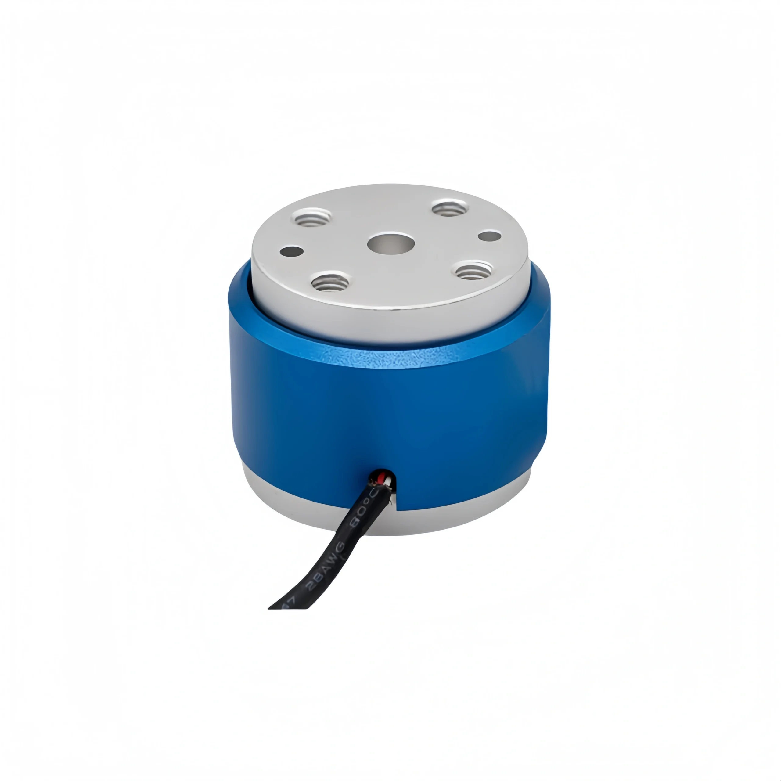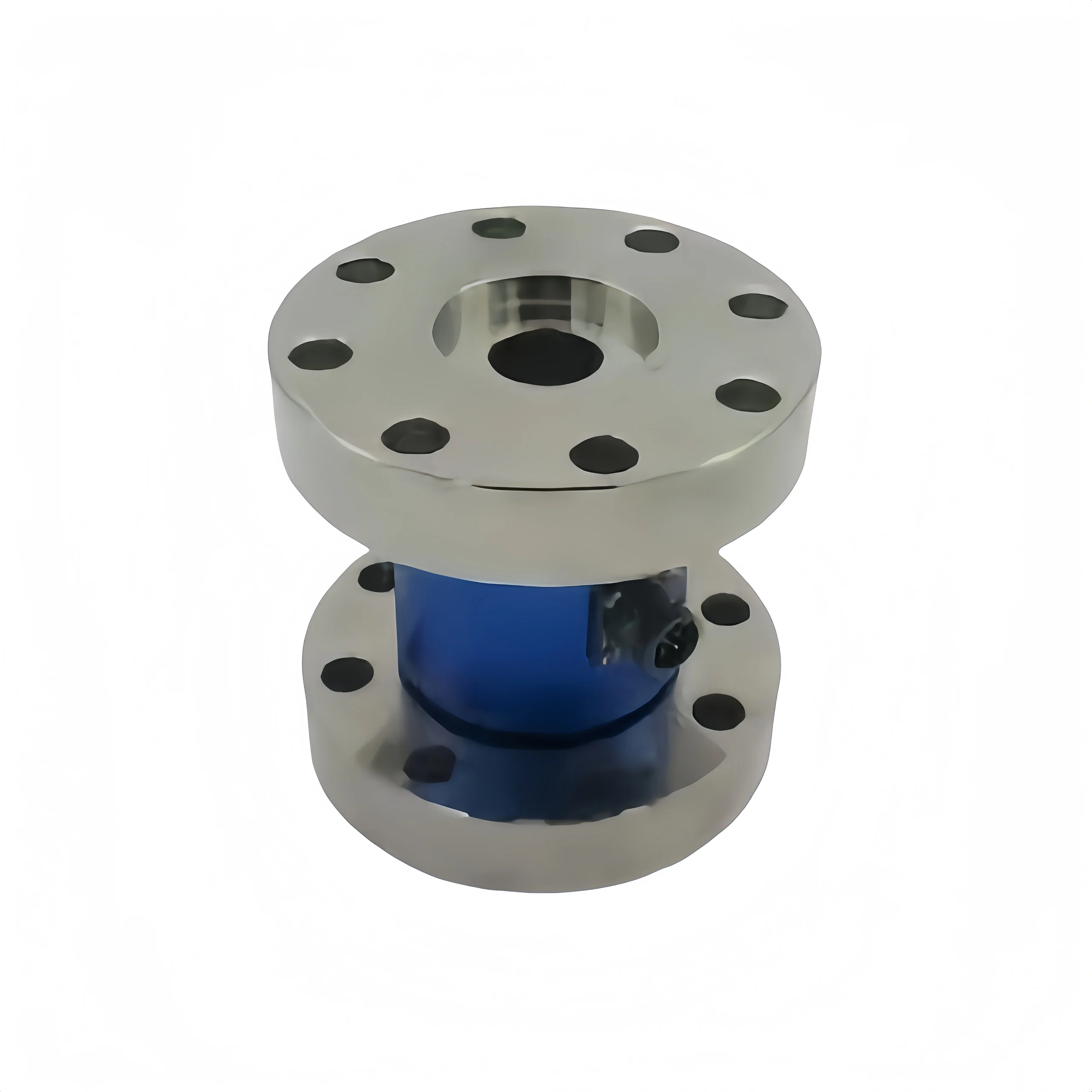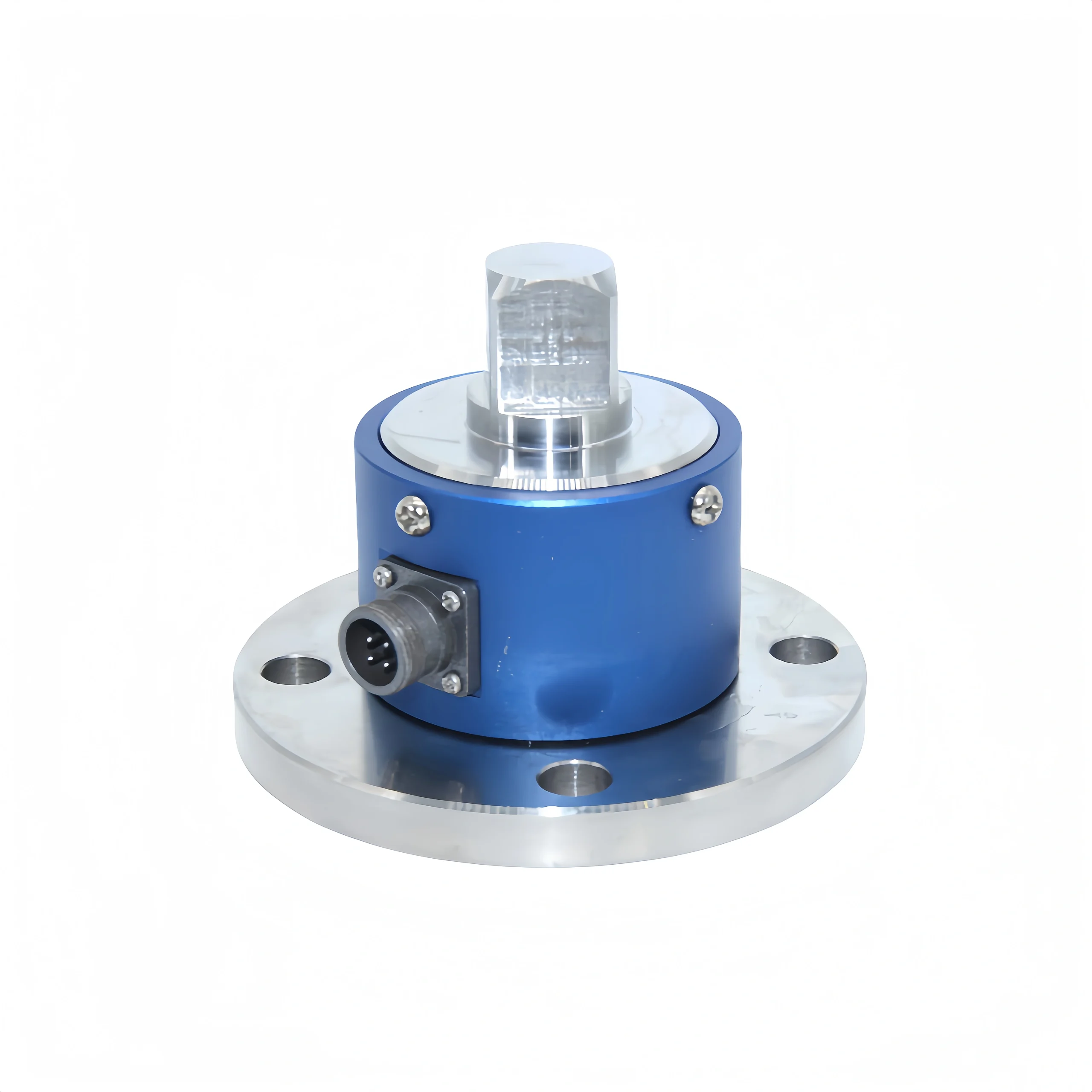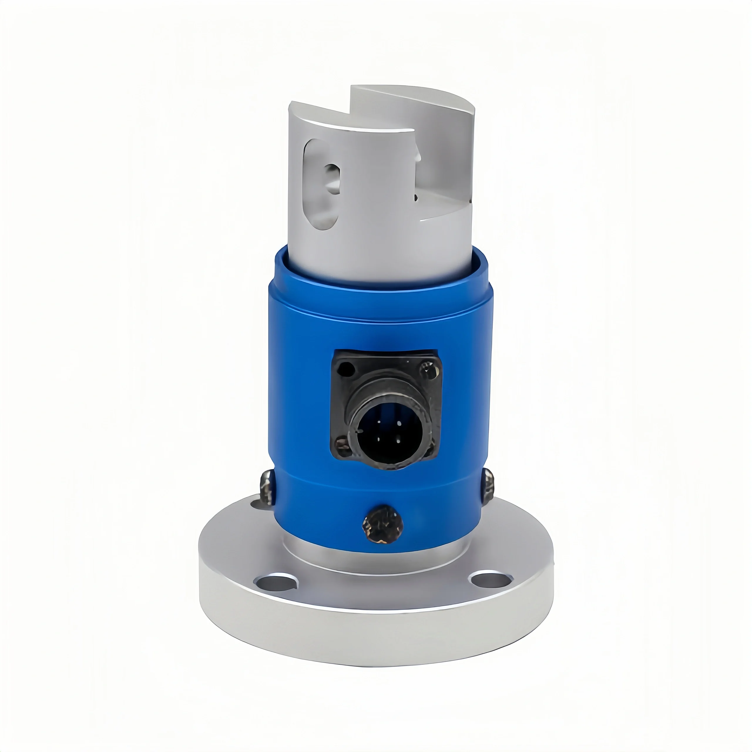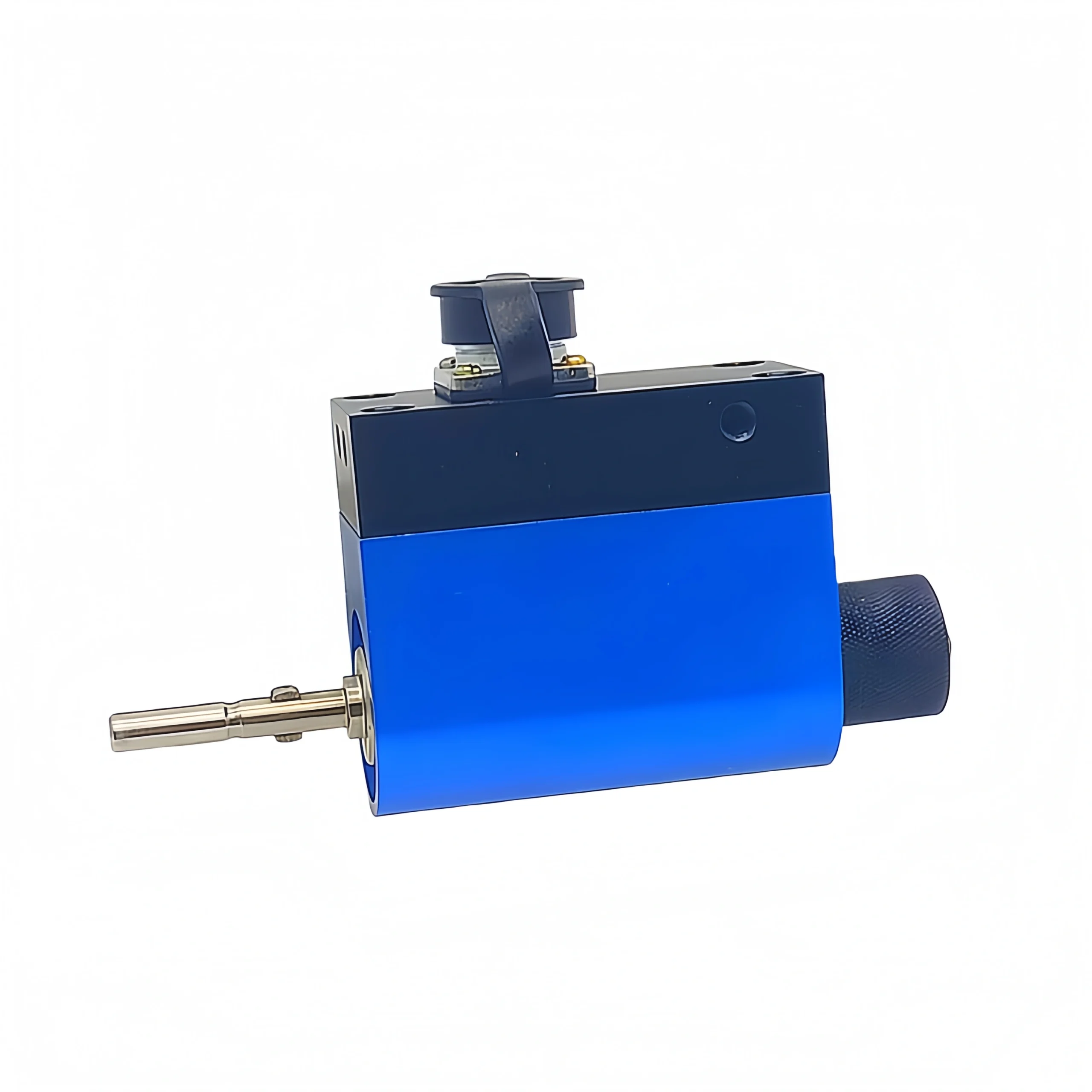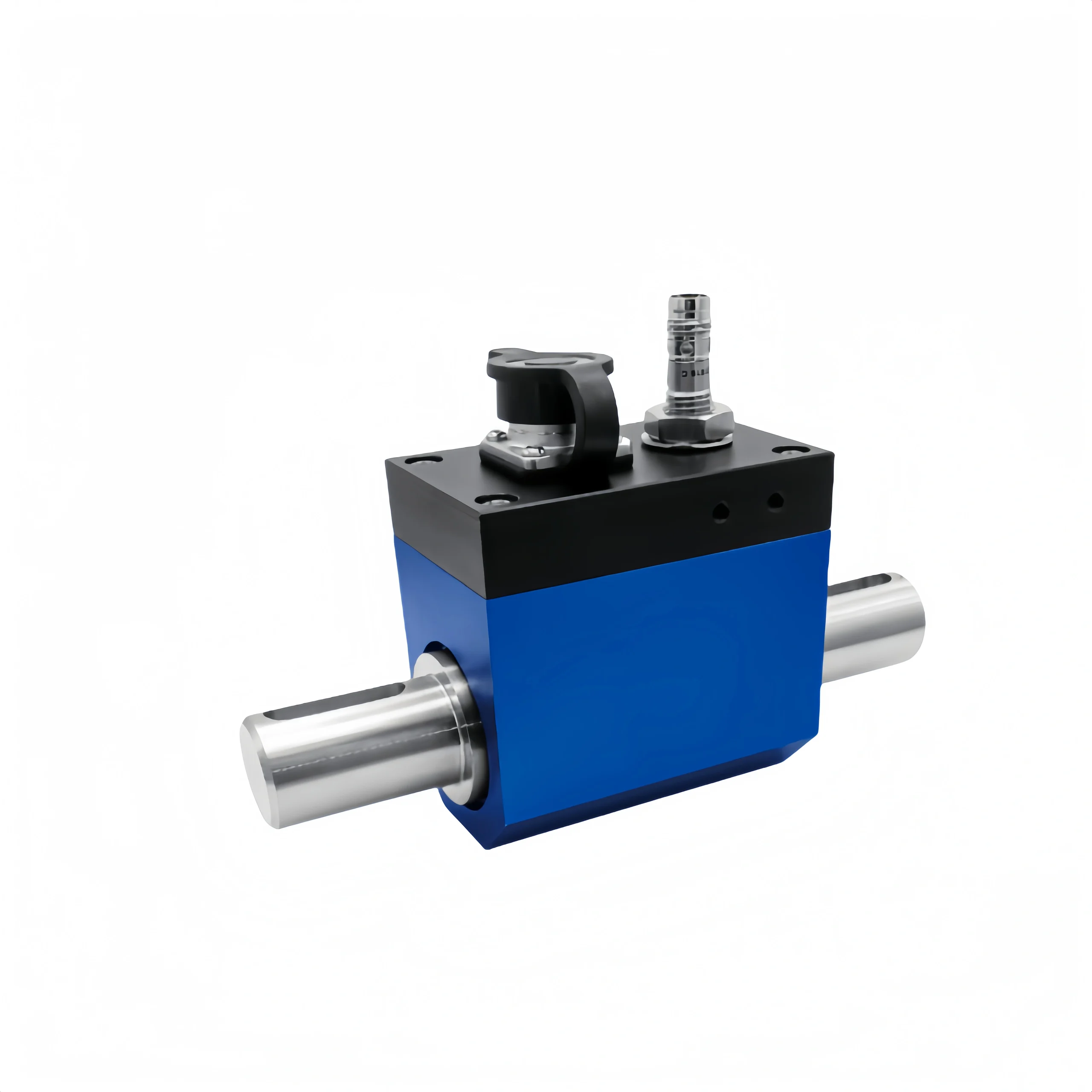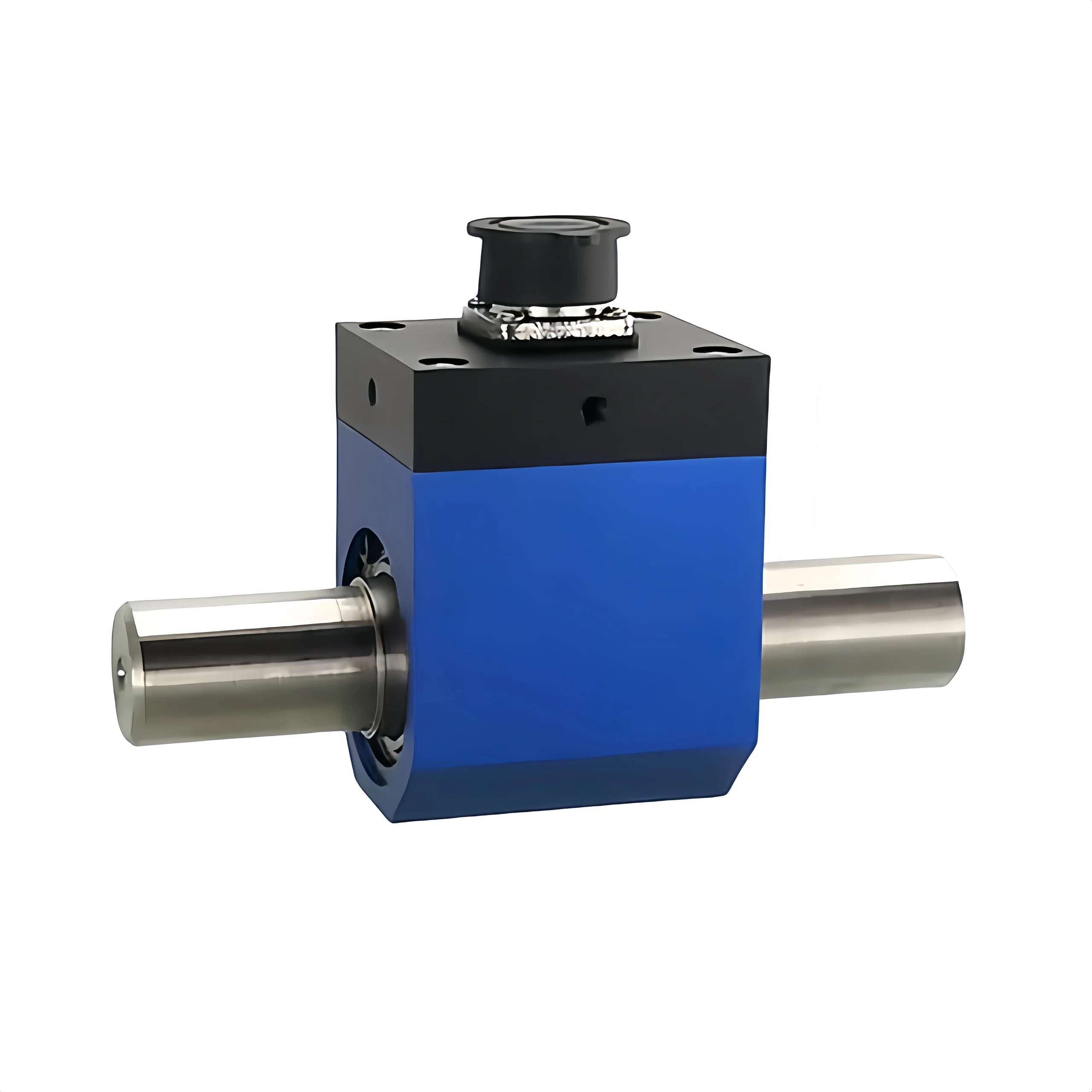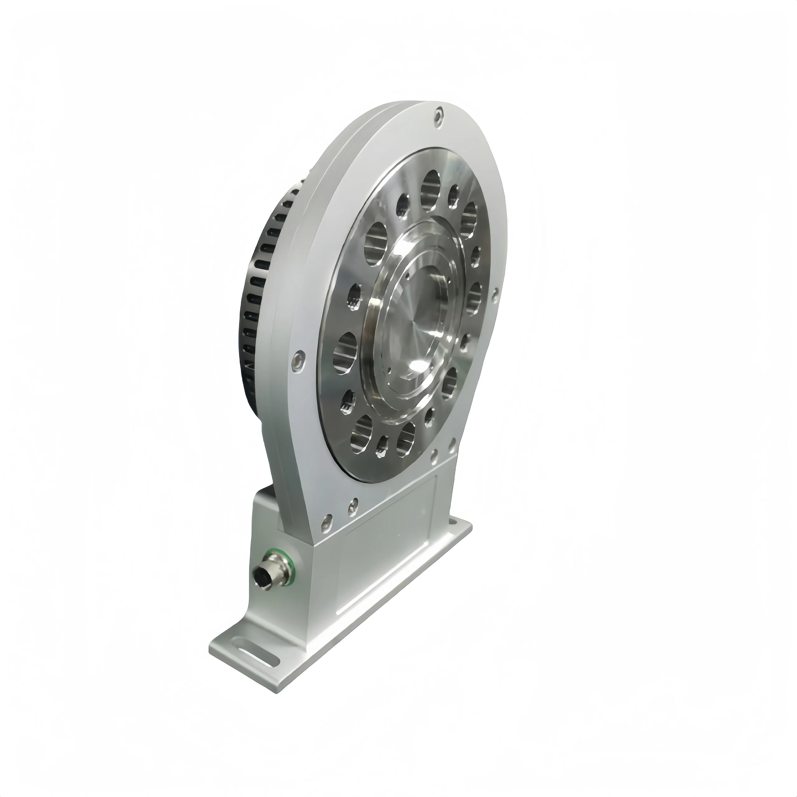
Reaction torque sensors are also called static torque sensors. Rotary torque sensors are also called dynamic torque sensors. Based on our years of experience in torque measurement, we have summarized the following differences.
1. Fundamental Difference: Location and Principle. Rotary torque sensors directly measure the torsional deformation of a rotating shaft. Reaction torque sensors measure the reaction force at a fixed end.
2. Core Measurement Capabilities: Rotary torque sensors measure dynamic (including static) forces. Reaction torque sensors primarily measure static and quasi-static forces.
3. Installation Complexity: Rotary torque sensors are more complex to install, align, and transmit. Reaction torque sensors are relatively simple to install.
4. Application Focus: Rotary torque sensors are used for monitoring and testing rotating systems. Reaction torque sensors are used for fixed loading, tightening, and quality control.
Based on our practical experience, if the rotational angle of the component under test is less than one full revolution, or if the rotational speed is very slow, a reaction-type torque sensor should be the preferred choice. If you need to measure the torque of a motor, gearbox, pump, or electric drive system while it is in operation, a rotary torque sensor should be used.
This article will specifically explain the differences between the two.
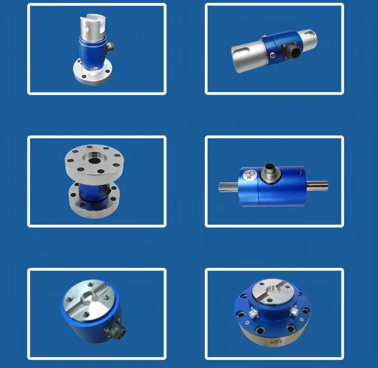

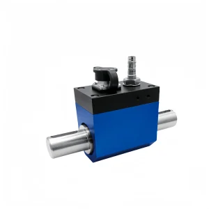
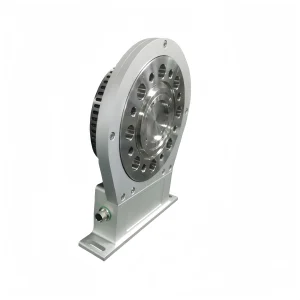
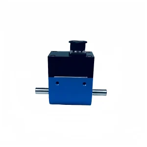
A torque sensor is a crucial instrument in mechanical dynamic testing. It can accurately measure static and dynamic torque. Models with a speed sensor also measure speed. Then shaft power and mechanical efficiency can be calculated. It converts changes in torque into electrical signals. Provide highly accurate data support for the test system. Its superior performance is its comprehensive measurement of static, rotating, and dynamic torque. It has high stability and strong anti-interference properties.
Furthermore, this sensor can continuously measure forward and reverse torque without repeated zeroing. Non-contact types have no wearing parts such as slip rings. It is suitable for long-term operation at high speeds. Its frequency signal can be sent directly to a PLC counter input or a data acquisition card. Provide powerful support for monitoring the operating conditions of mechanical power equipment.
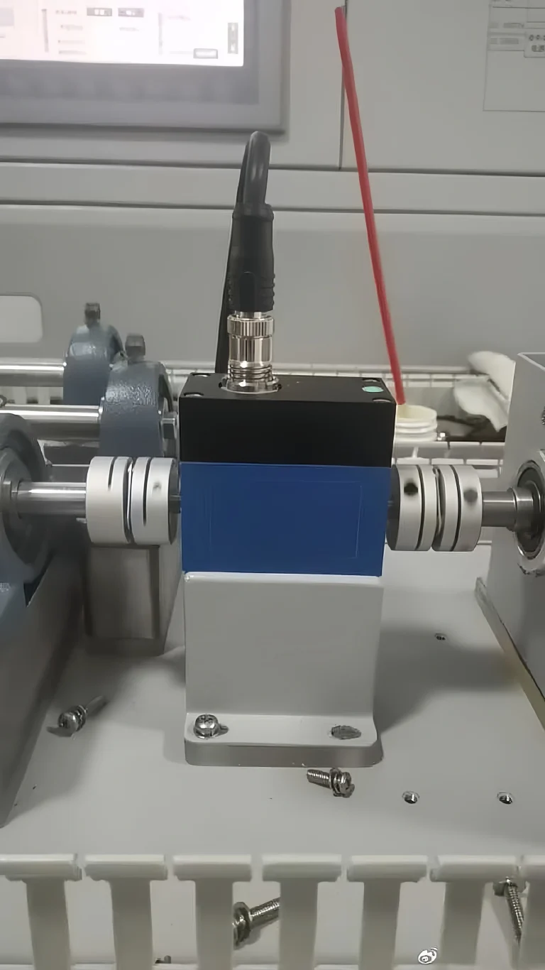
| Reaction torque sensor | Rotary torque sensor | |
|---|---|---|
| Where it sits | Between a non-rotating part and its mount | In the drive line, turning with the shaft |
| What it reads | Torque fed back into the mount | Torque transmitted through the shaft |
| Rotation | None, or limited angle | Continuous, up to the rated speed |
| Signal path | Plain cable | Slip ring, telemetry or non-contact coupling |
| Speed output | No | Optional built-in speed sensor |
| Installation | Bolt down, no shaft alignment | Two couplings, alignment needed |
| Typical uses | Wrench and screwdriver calibration, hinge and valve tests, fixtures | Motor and engine test benches, gearboxes, pumps, e-drives |
| Cost | Lower | Higher |
Torque measurements can generally be static or dynamic. Torque sensors are generally divided into two broad categories:
Static torque sensors, in which static or reaction force torque measurements involve little or no rotation of the measured item. such as during torque wrench testing.
Dynamic torque sensors, in which rotational torque measurements are subject to continuous rotation. This rotation can be constant, as found in systems measuring the torque of a stirrer in a mixing vessel, or periodic, as when measuring the torque generated by an electric screwdriver.
Working Principle
Rotary Torque Sensor
Measures the torsional deformation (strain) of a shaft.
Strain Gauge: The most common torque principle. Attached to an elastic shaft or through a specialized elastic body.
Piezoelectric Effect: Utilizes the charge output of a piezoelectric crystal proportional to torque (advantageous for dynamic measurement).
Phase Difference/Magnetoelastic: Measure the relative torsional angle between two segments on a shaft. Magnetoelastic utilizes the stress-magnetic effect of magnetic materials.
Reaction Torque Sensor: Measure the reaction force/torque applied to a fixed structure.
Strain Gauge: Attached to the elastic body of the sensor, such as a torsion shaft or a flange. Measures the shear strain caused by torque.
Piezoelectric Effect: Crystals generate a charge when subjected to force. Suitable for impact and fast-changing torque. Not suitable for long-time static measurement, because the charge signal drifts.
Measurement Objects:
Rotary Torque Sensor
Dynamic Torque: Measure torque values in real time during shaft rotation (from zero to very high speeds).
Reaction Torque Sensor
Static Torque: Measure torque at rest or very low speeds. It is primarily used for tightening and test bench fixed loading.
Quasi-Dynamic Torque: Measure torque changes at very low speeds.
Mounting Location
Rotary torque sensors:
Directly integrated (or used as test components) into the rotating transmission chain. Connecting the drive shaft and driven shaft at both ends.
Reaction torque sensors: Fixedly mounted on a non-rotating support. The driver (such as an electric wrench) typically acts on one end of the sensor or a connecting component. The other end of the sensor is fixed.
Signal Transmission Methods
Rotary torque sensors:
Signal transmission from the rotating component to the stationary component must be addressed:
– Slip rings: Contact-based and reliable. But subject to wear. electrical noise. and life limitations.
– Wireless (telemetry): Non-contact, long life, and strong anti-interference capabilities, currently the mainstream.
– Passive (inductive/magnetic):
Requires no batteries (or external power supply) and transmits energy and signals through inductive coupling or RFID principles. Result in a long lifespan but a complex structure.
Reaction torque sensors: Signal cables are directly routed from the fixed sensor. Eliminate the need for rotational transmission and simplify the connection.
Structure:
Rotary torque sensors typically consist of the following components:
Elastic element: Detects deformation caused by torque. And it is typically made of high-strength alloy steel.
Strain gauges: Attached to elastic elements, they convert deformation into changes in resistance.
Signal processing circuits: Amplify, filter, and process the strain gauge output signal.
Casings: Protect the sensor’s internal components. And they are typically made of aluminum alloy or stainless steel.
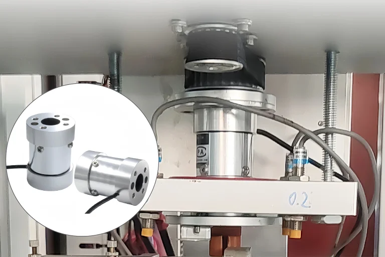
Reaction torque sensors consist of a measuring element, signal processing circuitry, and auxiliary components. The measuring element primarily consists of an elastic element and strain gauges. Together, they form the core of the sensor. The elastomer is a key component in sensing deformation during torque development. The strain gauge is tightly attached to the elastomer. Convert the deformation into a change in resistance.
Typical Applications
Rotary Torque Sensors:
- Engine/Motor Bench Testing
- Gearbox Testing
- Drive Shaft Torque Monitoring (Automotive, Marine, Wind Turbines)
- Motor Control and Efficiency Testing
- Any Application Where Continuous Torque Monitoring of a Rotating System is Required
Reaction Torque Sensors:
- Calibration and Monitoring of Tightening Machines (Screwdrivers, Electric/Pneumatic Wrenches)
- Material Testing Machines
- Static Loading on Test Benches
- Calibration of Torque Wrenches (with the sensor serving as a reference)
- Measurement of Torque Generated Discontinuously or at Low Speeds
Application Cases
Static torque test bench, Spain (reaction / static torque)
A test equipment maker in Spain asked for a “5 kN/m” sensor. We checked with the customer. The real need was a torque range of 5000 N·m. We supplied a dual flange static torque transducer with ±10 V output. Tip: confirm the unit and the connection type (flange, shaft or square drive) before you choose a sensor.
Motor test bench, USA (rotary torque)
An equipment developer in the USA tests small motors at up to 10,000 rpm. The shaft keeps turning, so only a rotary torque sensor can do this job. They use 5 Nm and 50 Nm rotary torque sensors with 0–5 V output. After using them for a while, the customer came back for more of the same sensors. Customer feedback: “This product is great and working really well for our application.”
Cost
Due to their simple structure, reaction torque sensors are less expensive than rotary torque sensors.
Main Advantages
Rotary Torque Sensors:
- Accurately measure dynamic torque at high speeds.
- Strong real-time performance makes them suitable for process monitoring and control.
- Measure starting torque at zero speed.
Reaction Torque Sensors:
- Relatively simple structure and generally lower cost.
- Easy to install (no need for precise drive train alignment).
- No rotating signal transmission device is required, making maintenance relatively easy.
Main Limitations
Rotary torque sensors:
- High cost (especially high-precision wireless or inductive types).
- High installation requirements: Requires precise machining, high concentricity, and complex calibration.
- Limited speed range (dynamic balancing is necessary at high speeds).
- Slip rings are subject to wear, and wireless models require power management.
- Replacement may affect the drive system (matching dimensions, flanges, keyways, etc. is required).
Reaction torque sensors:
- It cannot directly measure the dynamic torque of a rotating shaft.
- Only measures the torque at the fixed end. When mounted under a motor, it also includes the motor’s bearing and fan losses. During acceleration, it also includes the torque used to speed up the rotor. So the reading is not equal to the output shaft torque.
- Measuring torque at high speeds or under continuous rotation is extremely difficult or unsuitable.
- The rigidity of the sensor’s mounting structure can affect the measurement results. (The foundation must be stable.)
- Measurement accuracy of pure dynamic torque is lower than that of rotary torque sensors.
Accuracy
Rotary torque sensors:
Typically ±0.1% to ±0.5% F.S.
Good dynamic performance (depending on type and bandwidth).
Reaction Torque Sensors:
Typically ±0.1% to ±0.5% F.S. Mainly used for static or low-speed torque.
Overload Capacity
Rotary torque sensors:
Safe overload is typically 150% F.S. Ultimate overload is 200% F.S. Above this, the elastic body may be permanently damaged.
Reaction torque sensors:
Safe overload is typically 150% F.S. Ultimate overload is 200% F.S. Avoid impact loads above this range.
 In summary, both reaction torque sensors and rotary torque sensors play an important role in torque measurement. Choosing a torque sensor requires careful consideration. Sino-Inst offers a wide variety of torque sensors.
Our comprehensive selection of torque sensors, customizable to meet your measurement needs, is a must. If you need to buy a torque sensor or have any technical questions, please feel free to contact us. We are your best torque measurement friends.