A pressure transducer is a critical instrument used in various industrial process applications. And their measurement accuracy usually impacts industrial safety and efficiency. Accurate calibration of pressure transducers ensures data reliability.
The post introduces the terminology, progress, and precautions related to pressure transducer calibration.
What is Pressure Transducer Calibration?
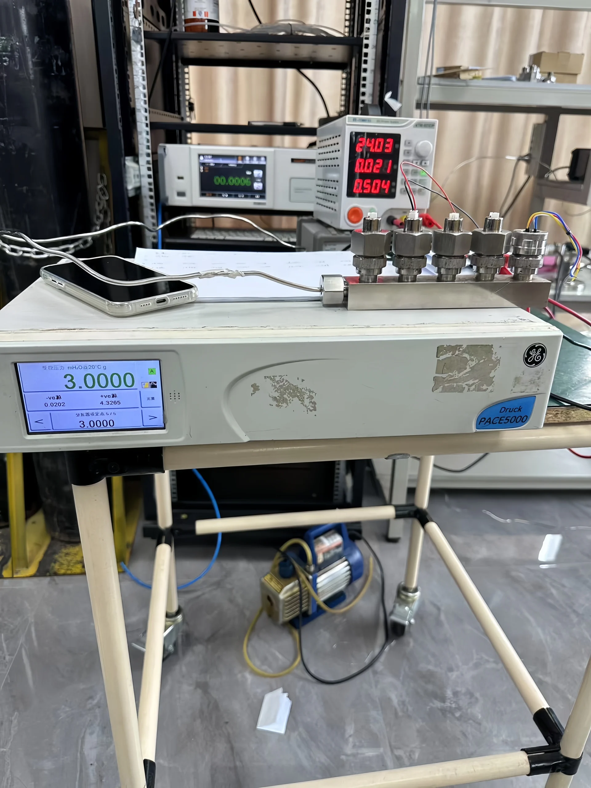
Pressure transducer calibration refers to comparing the pressure transducer’s measured output with known standard pressure data to determine the measurement error. We adjust the transducer or provide calibration values to improve measurement accuracy.
The process uses a standard pressure source to provide a precise pressure reference. We compare the transducer’s output signal (e.g., 4-20mA current) with the standard value. We calculate the error and adjust it to ensure it meets accuracy.
There are some usual calibrations:
- Zero-point calibration: Setting the output to zero value when there is no pressure.
- Span calibration: Adjusting the output at full-scale pressure.
- Linearity verification: Evaluating output linearity through multi-point testing
The main purpose of calibration is to eliminate errors generated during the production, transportation, and use of transducers. They can ensure the accuracy and reliability of measurement results and meet the safety and compliance requirements of industrial process control.

Pressure Transducer Calibration Progress
Calibrating a pressure transducer is a complex process. We have compiled a general calibration process for you. For some important points, we recommend consulting your supplier or relevant professionals.
1. Preparation before calibration:
Before calibration, we should ensure power and signal cable connections are safe. Check the calibration equipment for damage. Most importantly, prepare the useful calibration equipment, such as a standard pressure source, digital multimeter, and constant current source. If the measured medium is corrosive, an isolation device is also required.
2. Five-Point Calibration Progress
- Zero-Point Calibration: Under no-pressure conditions, we adjust the zero-point potentiometer to output 4mA (or 1V).
- Range Calibration: Input full-scale pressure and adjust the range potentiometer to 20mA (or 5V).
- Midpoint Verification: Input 25%, 50%, and 75% of the range pressure, respectively. And record the drift between the output data and the theoretical data.
- Repeatability Test: Perform three cyclic tests on the same pressure point. And calculate the repeatability error.
- Hysteresis Error Detection: After pressurizing to full scale, gradually decrease the pressure and observe the consistency of the rising/falling curves.
3. Data Recording and Error Analysis
Use calibration software or manually to record the input pressure, output signal, theoretical value, and error at each test point. If nonlinearity or excessive hysteresis is found, the sensor may need to be replaced or returned to the factory for repair.
4. Post-Calibration
After calibration, the pressure transmitter needs to be tested. The purpose of the test is to ensure that its output signal matches the required pressure output value. If it matches, the calibration is successful. Testing can be performed using calibration equipment. Alternatively, the pressure sensor can be reconnected to the actual operating system for application testing.
5. Record Calibration
Finally, the specific calibration process and results should be recorded. The record should include the calibration date, calibration equipment model, calibration parameters, and calibration results. The record helps evaluate the pressure transducer’s performance and facilitate subsequent pressure transducer calibration.
Sino-Inst Featured Pressure Transducer
Pressure Calibration Related Terminology
For some tiros, some related terminology during calibration may be confusing. Here is an introduction to relevant calibration terminology.
Accuracy:
It refers to the data for which the measured result closely approximates the true data. For example, an accuracy of ±0.5% means that the error between the measured result and the true pressure is within 0.5% of the true value.
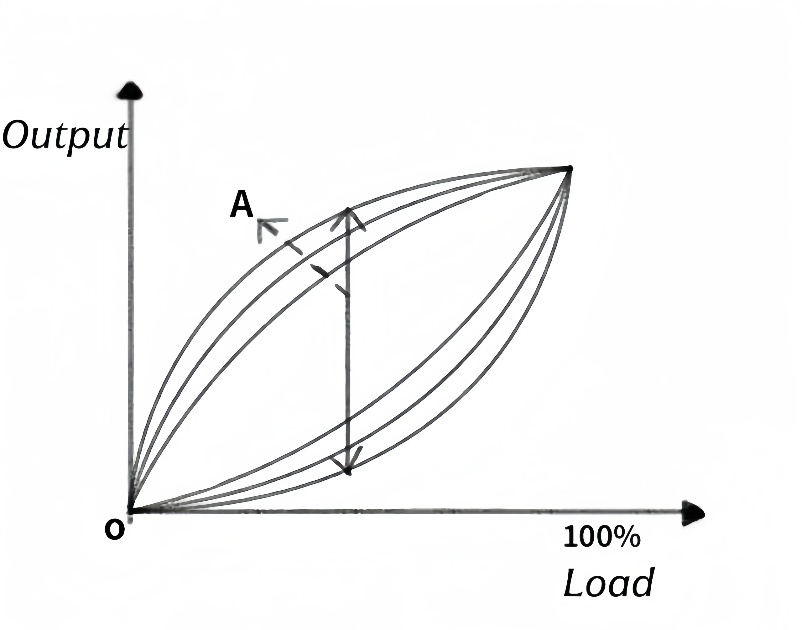
Hysteresis:
During the calibration of a pressure transducer, the pressure is sensed through an isolation diaphragm and pressure taps. Although the input is standard, the direction and magnitude of pressure loading and unloading under actual operating conditions will cause differences in the amplitude of the pressure sensor’s output electrical signal. The phenomenon that the input and output featured curves do not overlap during the forward and reverse strokes is called hysteresis.

Linearity:
Linearity is the linear relationship between the transducer’s output signal and the input pressure. The purpose of calibrating linearity is to ensure that the transducer has high linearity within its measurement range and to reduce non-linear errors.
Repeatability:
Repeatability is the consistency of the transducer’s output signal when measured repeatedly under the same pressure. Repeatability improves the transducer’s measurement stability.
Stability:
Stability is an important indicator of pressure transducer performance, especially in applications requiring accurate and reliable measurements.
Zero Drift and Temperature Drift
Read More about: PT Compensation of Flow Measurement
Zero drift refers to the phenomenon where the output quantity changes over time when the transducer’s input and ambient temperature remain constant. It is caused by instability in the performance of various components within the sensor or changes in its internal temperature, reflecting an indicator of the transducer’s stability.
Useful Solutions for Zero-Point Drift:
Adjust Zero Point:
Use the adjusting screw or digital regulator to adjust the zero point so that the output signal returns to the correct zero point.
Sensor Replacement:
If zero-point drift is too frequent or cannot be calibrated, the pressure sensor may need to be replaced.
Pressure Drift of Pressure Sensor:
Temperature drift refers to the shift in the pressure transmitter’s output signal as temperature changes, leading to inaccurate measurements. We have summarized some common methods for addressing temperature drift:
Using Temperature Compensation Technology:
Hardware Compensation:
When designing pressure sensors, manufacturers should employ a dual-sensor structure: one for measuring pressure and the other for measuring temperature. Using built-in formulas, the measured temperature value can be used to compensate for he pressure sensor’s output in real time.
Software Compensation:
For some intelligent pressure transducers, algorithms can be embedded in the internal circuitry to digitally compensate the output signal.

Why Should You Calibrate Pressure Transducers?
The accuracy of pressure transducers usually affects the product quality of the entire production process. In many industrial applications, pressure changes can lead to equipment failure and safety accidents. So, ensuring the accuracy of pressure transducers is crucial. Over time, pressure transducers may be affected by environmental changes, mechanical wear, and other factors. They lead to a decrease in their measurement accuracy.
In long-term use, the accuracy of pressure transducers may decrease due to various factors such as media corrosion, mechanical fatigue, and temperature drift. Zero drift can also cause a decrease in accuracy. These different factors lead to a gradual increase in measurement error. Regular calibration can correct these errors and ensure a smooth equipment operation.

Calibration Traceability and Pressure Standards
The accuracy of the calibration equipment usually has a sufficient margin relative to the pressure transducer being calibrated. The accuracy of the standard pressure source should be an order of magnitude higher than that of the pressure sensor. The accuracy of the instrument used to measure the sensor’s output signal must also meet requirements, and its measurement error should be within acceptable limits.
The trust of calibration data depends on the traceability of the calibration equipment. The standard pressure source and measuring instruments used for calibration should be traceable to national and international standards. The calibration certificate should state its measurement uncertainty and its correlation with higher-level standards. If the origin of the calibration equipment cannot be traced, the reliability of the calibration data cannot be trusted.
Factors Affecting Pressure Transducer Calibration
Pressure transducer calibration results are easily affected by many factors during the experiment.
- Stable environmental conditions should be selected during verification and calibration to avoid the influence of environmental factors such as temperature and humidity on the test results.
- Workers should be professionally trained and familiar with the working principle of the pressure transducer and the verification and calibration process to ensure the accuracy and safety of the verification and calibration process.
- In addition to regular calibration, daily maintenance is also necessary to ensure the stability of the pressure transducer. The connection status, appearance, and operating status of the transducer should be checked regularly. And any abnormalities should be addressed promptly.
- When we calibrate, nationally or industry-recognized standard equipment should be used to ensure the reliability of the calibration results.

Instruments Used in Pressure Transducers Calibration.
Pressure Standards (Pressure Source and Pressure Standard Gauge):
Pressure Standard Gauge:
An instrument has an accuracy higher than the pressure transducer being calibrated. In general, at least 3-4 times the accuracy of the transducer being calibrated. This can be an accuracy pointer pressure sensor, a digital pressure calibrator, or a higher-level pressure transducer.
Pressure Source:
It is capable of generating stable, accurate pressure covering the transducer's range. This can be a manual/electric pneumatic pump, a hydraulic pump, or a pressure controller with higher accuracy.
Signal Measurement Equipment:
Precision Ammeter: Used to measure analog output current signals. It requires sufficiently high accuracy.
Precision Voltmeter: Used to measure voltage outputs (e.g., 0-5V, 1-5V).
• Digital Communication Interface and Software: Used to read and set transducer information for digital outputs via bus protocols (HART, Profibus PA, Foundation Fieldbus, etc.).
• Process Calibrator: Integrates the above functions (pressure measurement, signal measurement, and excitation, HART communication). And it is a commonly used choice.
How Often Should You Calibrate Pressure Transducers?
There are no mandatory fixed requirements for pressure transducer calibration. Companies can generally establish their own standards. Normally, calibration once a year is sufficient. However, for critical equipment, we can shorten the calibration cycle.
How to calibrate a differential pressure transducer?
Preparation for Field Calibration of Differential Pressure Transducers. The usual practice is to disconnect the pressure lines and the differential pressure transducer connectors before connecting the pressure source for calibration.
Regardless of the model, differential pressure transducers have vent and drain valves or stopcocks in both the positive and negative pressure chambers. This facilitates field calibration of differential pressure transducers. It allows calibration without removing the pressure lines. However, a connector with the same thread as the vent/drain valve or stopcock needs to be fabricated, as shown in the figure. The thread material shown should be machined according to the thread specifications of the transducer's vent/drain valve or stopcock.
When calibrating the differential pressure transducer
First, close the positive and negative valves of the three-valve manifold. Open the balancing valve, and then loosen the vent/drain valve to release air. Then, use the self-made connector to replace the vent/drain valve or stopcock connected to the positive pressure chamber. The negative pressure chamber should remain loose, allowing it to vent to the atmosphere. Connect the pressure source to the self-made connector via a rubber hose, close the balancing valve, and check the air circuit seal. Then connect the ammeter (voltmeter) and handheld communicator to the differential pressure transducer circuit, and power on. And preheat before starting calibration.
On-site Calibration of Conventional Differential Pressure Transducers:
First, adjust the damping to zero, then adjust the zero point, and then apply full-scale pressure to adjust the full range, making the output 20mA. On-site calibration should be quick; here, a quick calibration method for the zero point and range is introduced.
Adjusting the zero point has almost no effect on the full-scale reading. But adjusting the full-scale reading does affect the zero point. Without a range shift, this effect is approximately 1/5 of the range adjustment. That is, adjusting the range upwards by 1mA will move the zero point upwards by about 0.2mA. For example, if the input full-scale pressure is 100kPa, the reading is 19.900mA.
Adjusting the range potentiometer to make the output 19.900 + (20.000 - 19.900) × 1.25 = 20.025mA increases the range by 0.125mA, thus increasing the zero point by 1/5 × 0.125 = 0.025mA. Adjusting the zero point potentiometer to make the output 20,000mA. After the zero point and full-scale range are correctly calibrated, check the intermediate scales. If they are out of tolerance, make fine adjustments. Then perform range shift, linearity, and damping adjustments.
All in all, the calibration process for the pressure transducer is described in the manufacturer’s instruction manual. If you still have questions about the calibration of your pressure transducer, please contact us immediately. Sino-Inst is a pressure transducer supplier from China with over 20 years of experience. We also have professional engineers to provide you with free technical support.


