How does a Temperature Transmitter Work?

Table of Contents

Temperature is a critical parameter in industrial processes. Temperature transmitters are essential for both processing and temperature control. They can monitor temperature information for production safety and processing quality. Therefore, they play a vital role in temperature control.

This article primarily explains the working principles of temperature transmitters. Hopefully, this article will provide you with a general understanding of temperature transmitters.

What is a Temperature Transmitter?

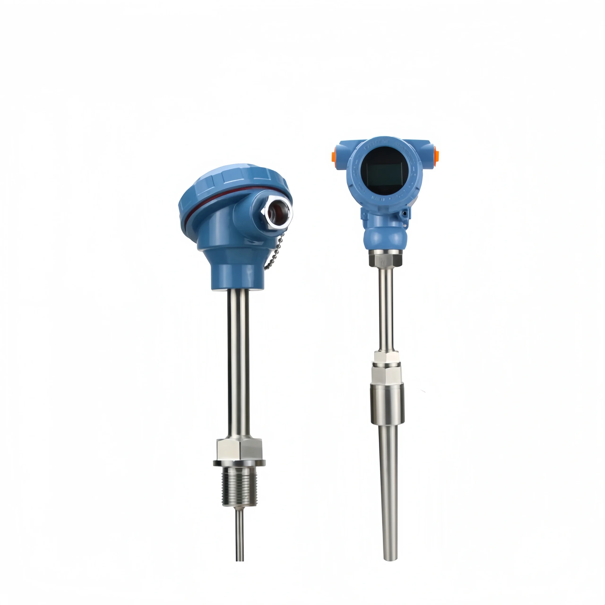
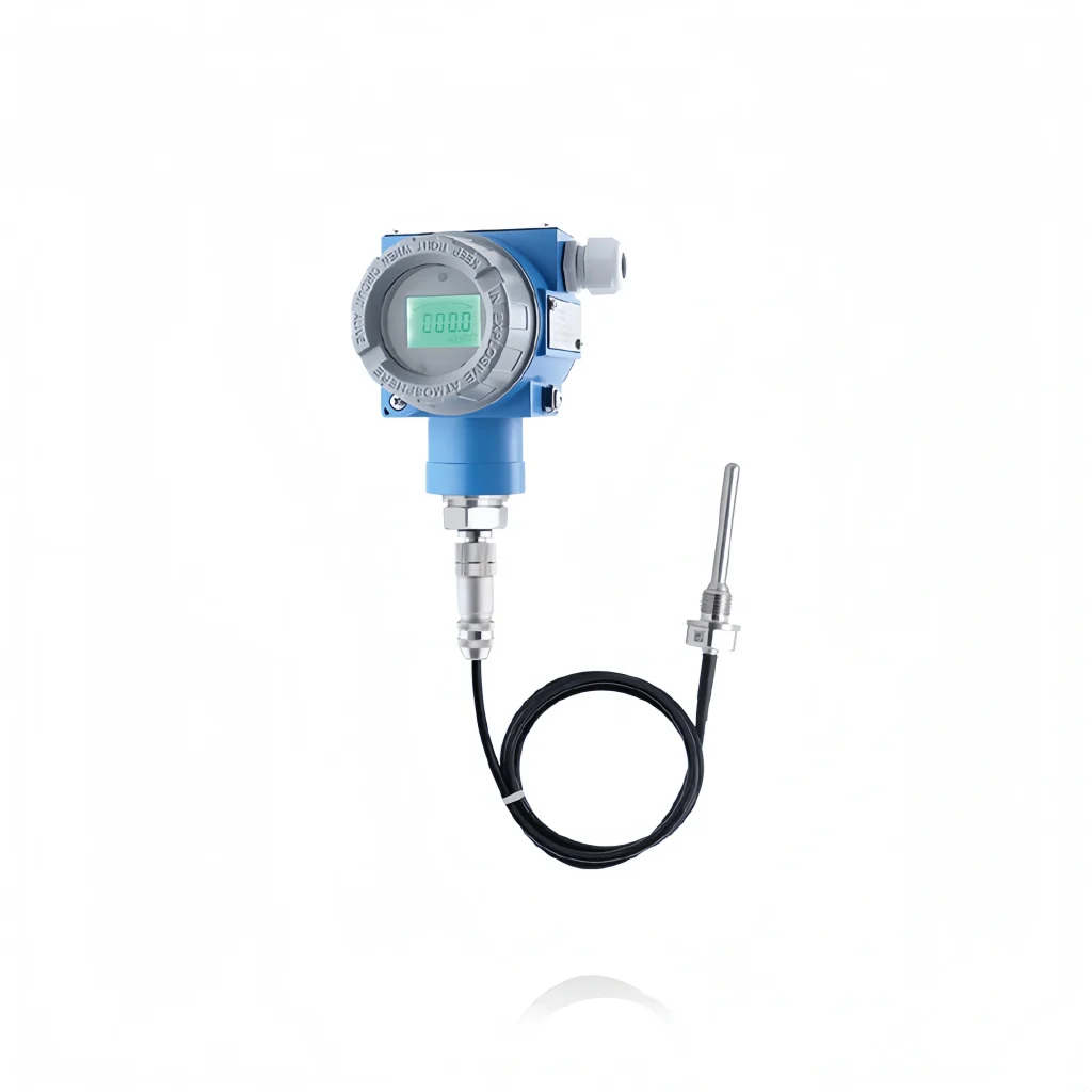
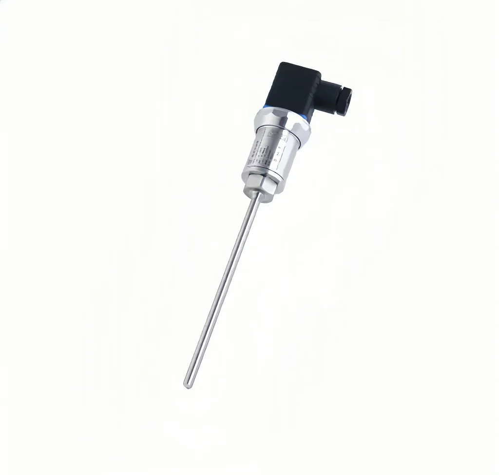
A temperature transmitter converts temperature signals into a standard electrical signal. It is primarily used to measure and control temperature parameters in industrial processes. A current transmitter converts the measured main circuit AC into a constant current loop standard signal and continuously transmits it to a receiving device.

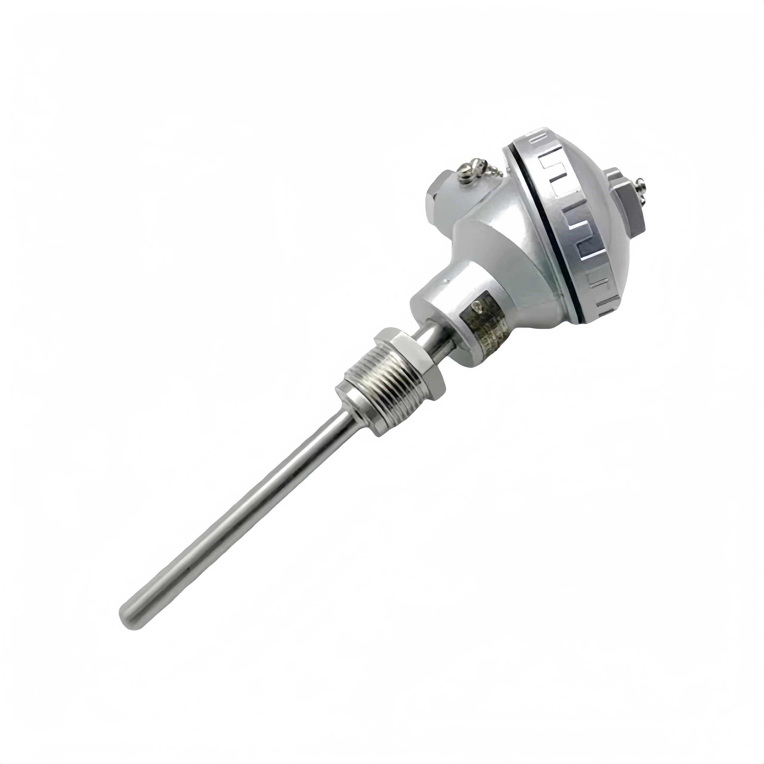
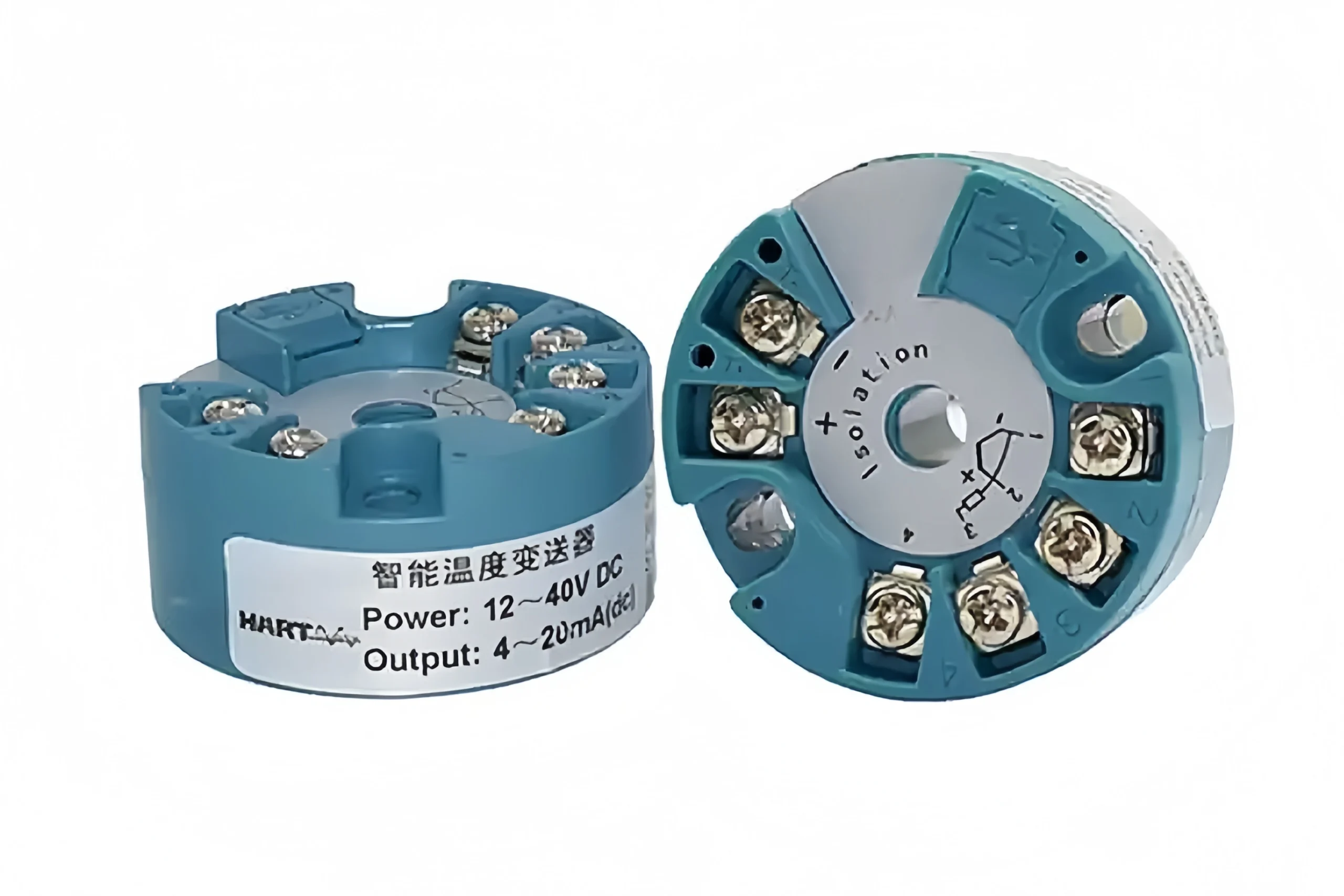
Temperature transmitters use thermocouples and RTDs as temperature measuring elements. The output signal from the measuring element is sent to the transmitter module. After processing through circuits including voltage stabilization and filtering, operational amplification, nonlinearity correction, V/I conversion, constant current, and reverse protection, the signal is converted into an electronic signal output. The signal is linearly related to temperature.

Hart RTD Temperature Transmitter

Advantages:

  • High-precision measurement;
  • Good stability;
  • Strong anti-interference capability;
  • Wide range of applications.

Disadvantages:

  • High price;
  • Complex installation;
  • Reliant on an external power supply.

How does a Temperature Transmitter Work?

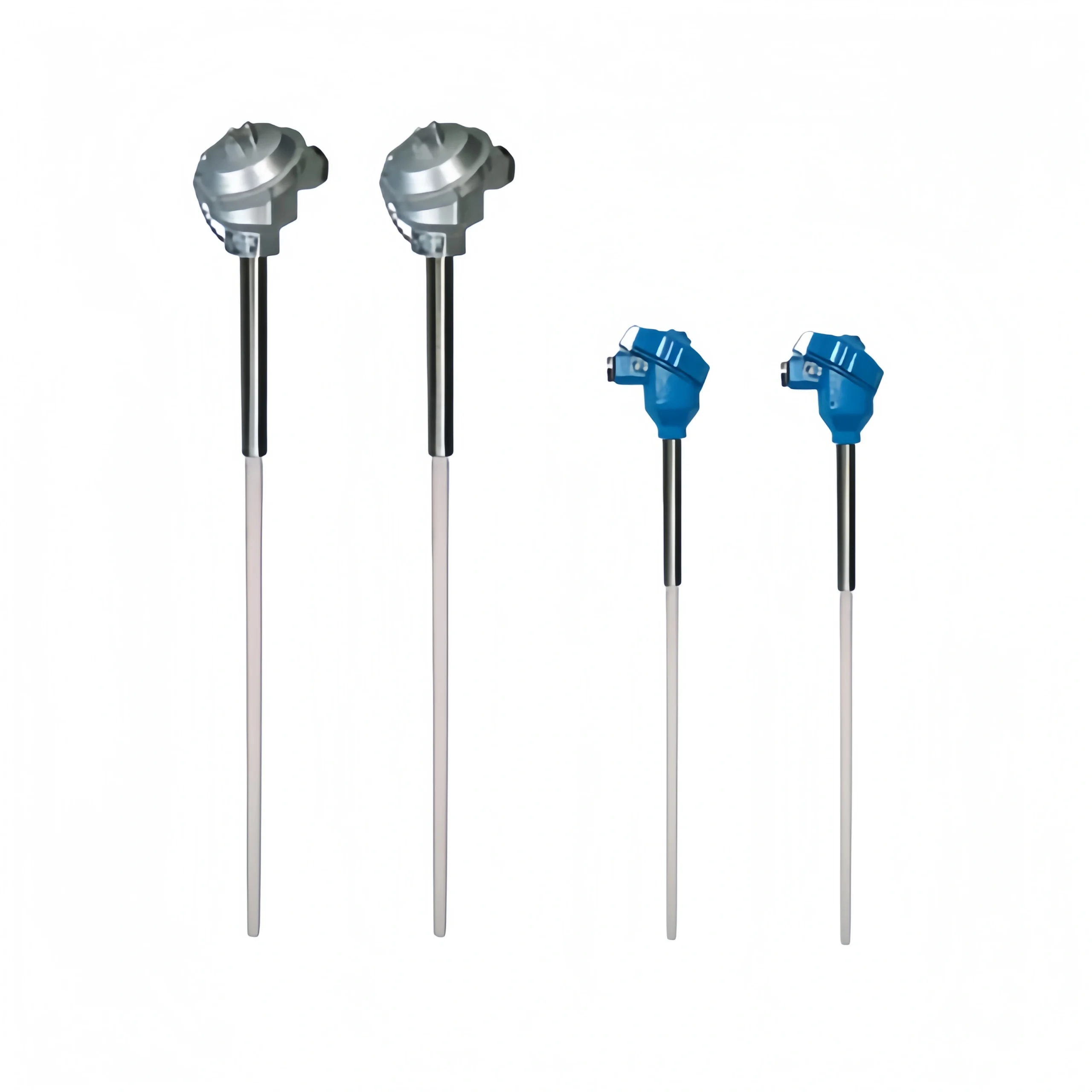
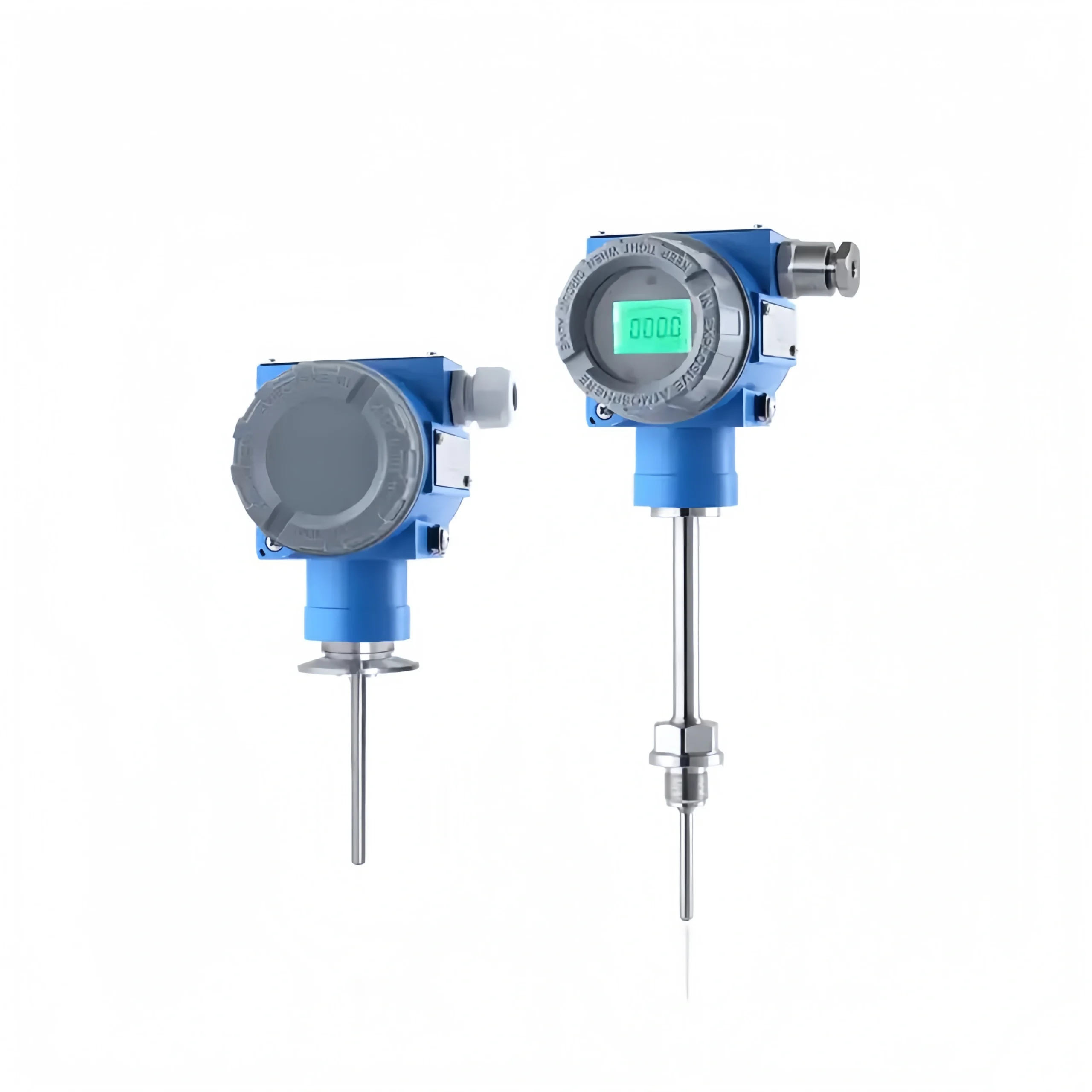
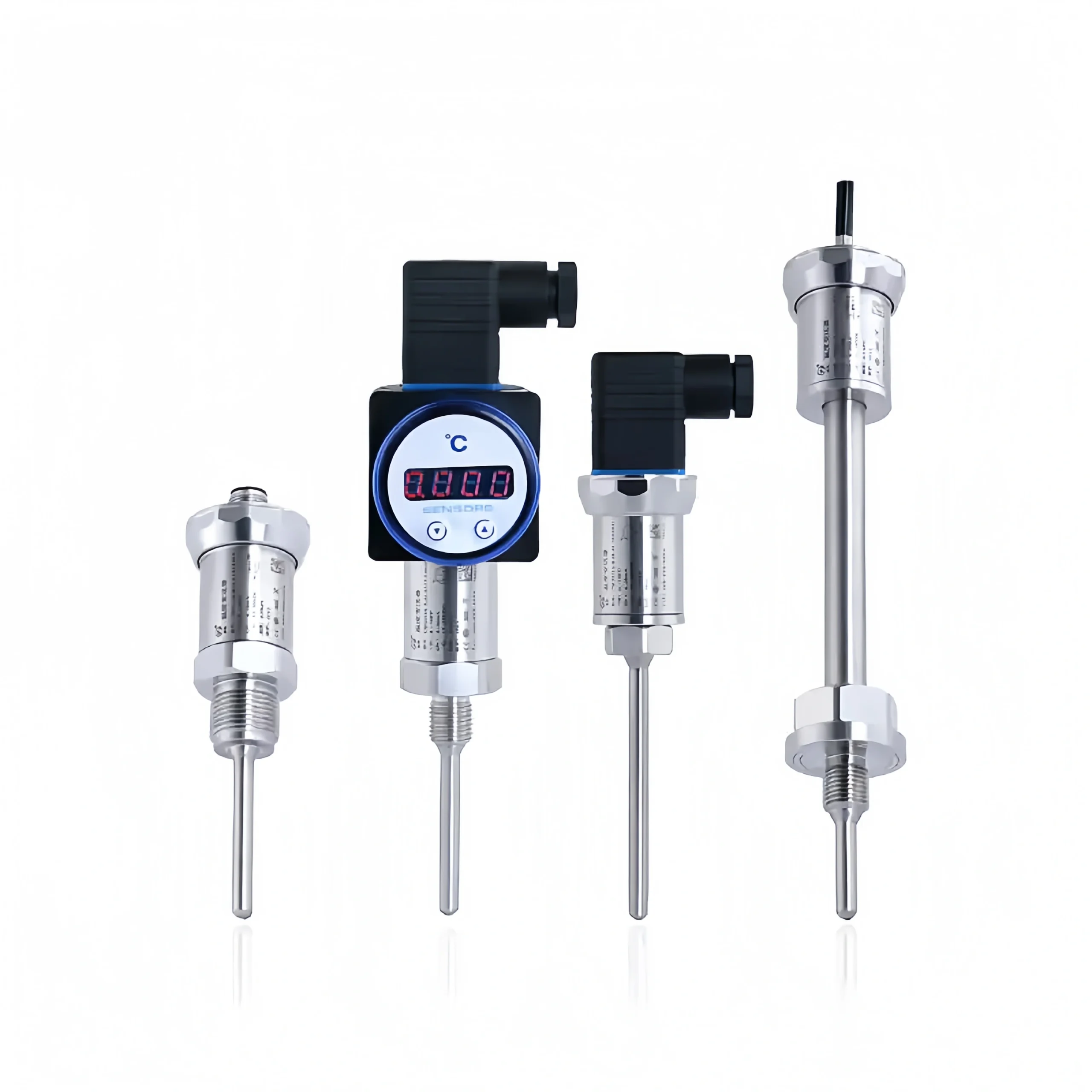
Temperature transmitters are mainly divided into thermocouple temperature transmitters and RTD temperature transmitters.

The thermocouple temperature transmitter mainly utilizes the Seebeck effect to measure temperature. It consists of a reference source, a cold-junction compensation circuit, an amplifier unit, a linearization module, a voltage-to-current converter, and some protection circuits.

The core function of a thermocouple temperature transmitter is to convert the weak thermoelectric potential generated by the thermocouple into a standard electrical signal after cold-junction temperature compensation and signal amplification. This standardized signal is highly resistant to interference and can be transmitted over long distances. It can also be directly connected to devices. such as display instruments, controllers, recorders, or distributed control systems (DCS or PLC).

Anti-corrosion temperature transmitter

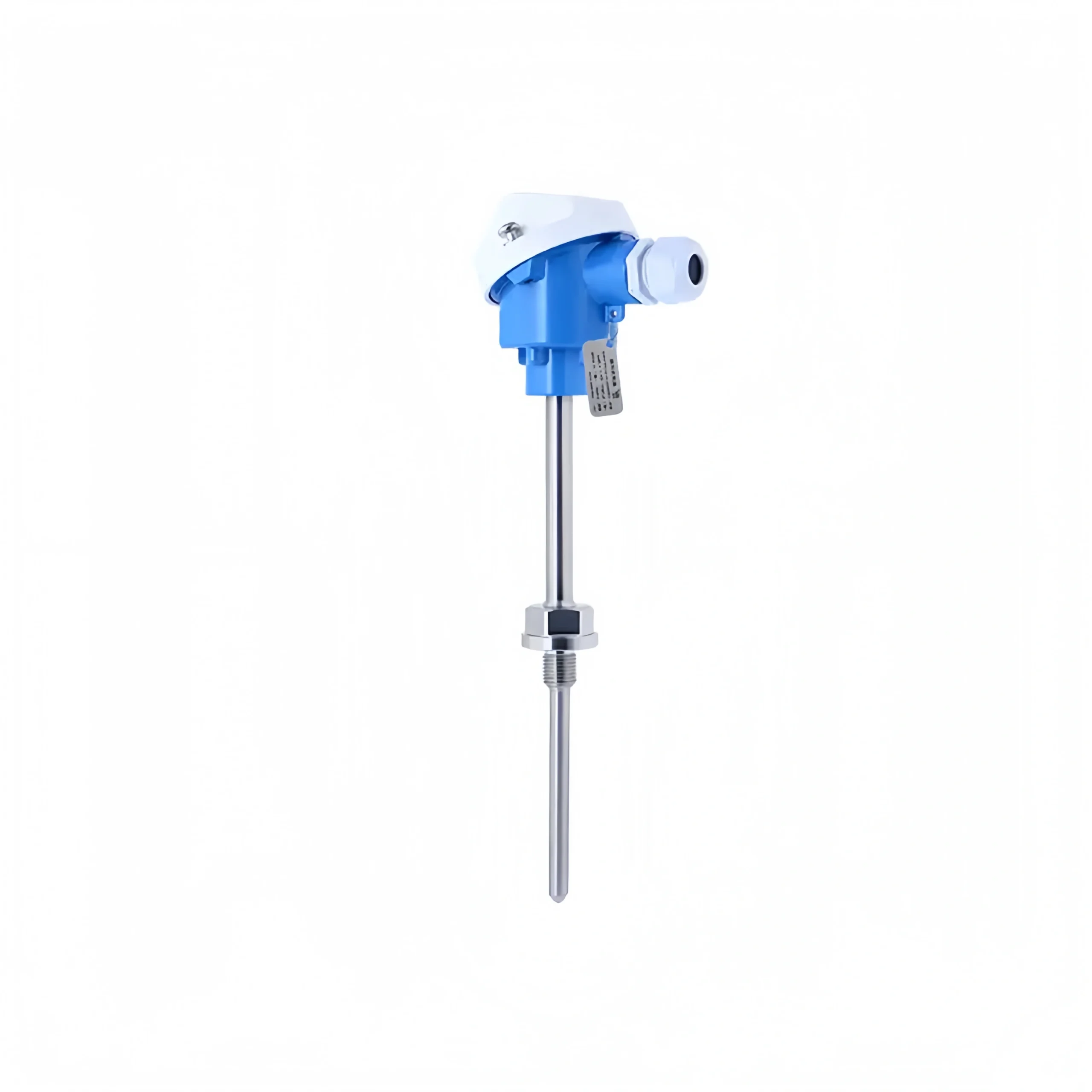
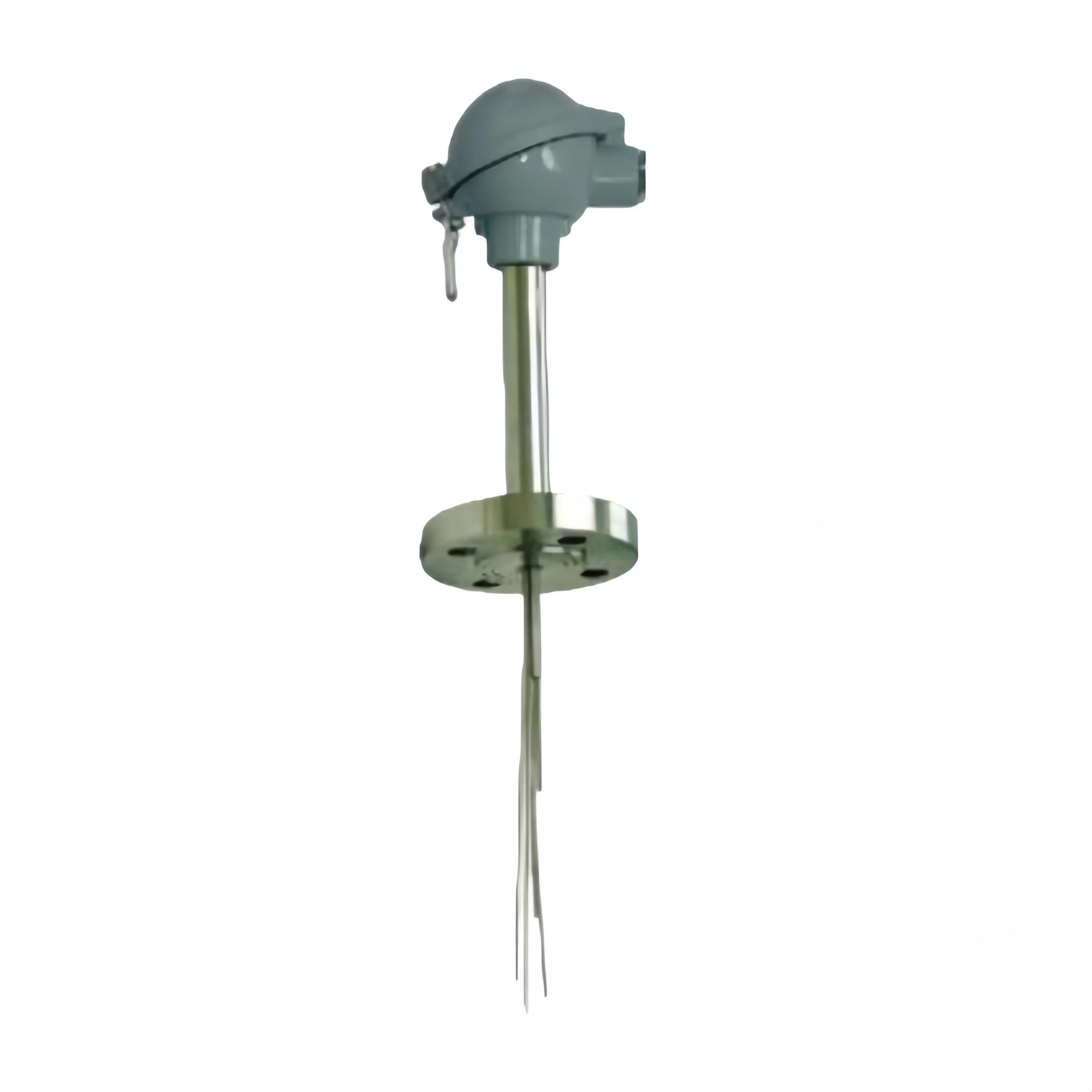
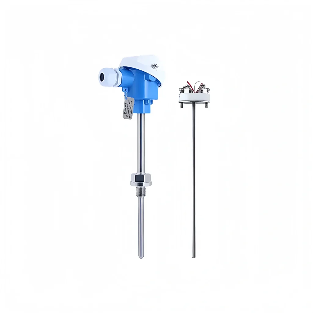
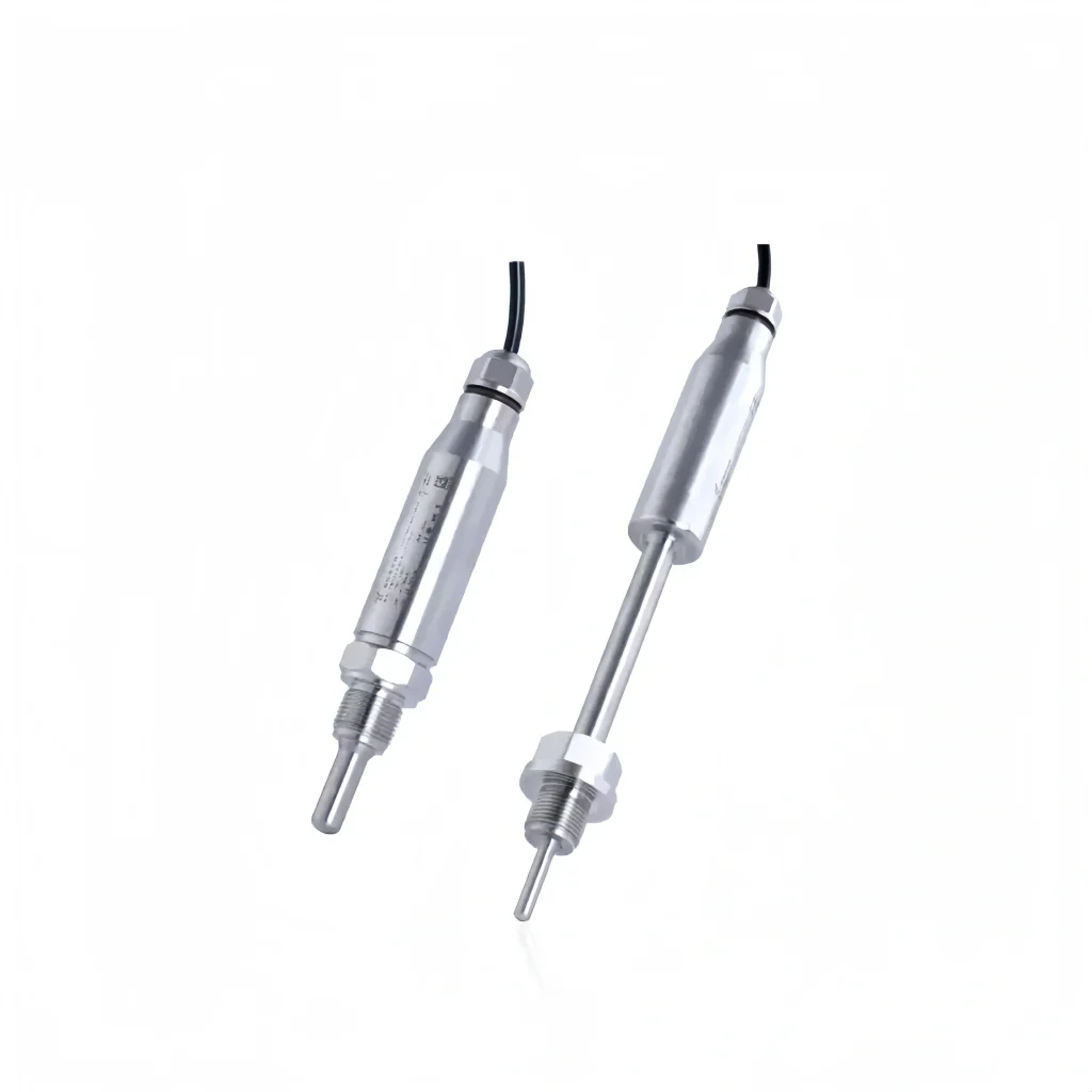
A resistor temperature transmitter(RTD) measures temperature based on the electrical resistance properties of metals. These resistors are typically made of platinum, copper, or nickel. They have a special resistance value to a particular temperature (such as 0°C or 100°C). As the temperature changes, the resistance also changes proportionally.

To measure temperature, an RTD sensor is connected to a temperature transmitter. The measuring device sends current into the sensor circuit and reads the voltage across the RTD.

This voltage reflects the sensor’s resistance and, therefore, the current temperature. The measuring device converts the voltage across the sensor into a temperature display or control signal, thus achieving accurate temperature monitoring.

Sino-Inst Featured Temperature Transmitter

Sanitary temperature transmitter installation type
Sanitary temperature transmitter
Immersion temperature transmitter
Waterproof temperature transmitter
Waterproof Temperature Transmitter
Remote Temperature Transmitter
Explosion-proof temperature transmitter
Intelligent Explosion-Proof Temperature Transmitter
General Purpose Temperature Transmitter

Temperature Transmitter Input Signal

Temperature transmitter input signals come in two types: RTDs and thermocouples. The following is a detailed description:

RTD Input Signal

Based on the element structure, RTD input signals can be categorized as either wire-wound RTDs or thin-film RTDs. The following is a detailed introduction.

1. Wirewound RTD

This type of RTD has a small-diameter wire, most commonly platinum, wound into a coil placed within a ceramic/glass insulator. Extension wire is soldered to this platinum coil, which extends outside the insulator. Compared to thin-film sensors, this type of sensor is longer and more delicate. Wirewound RTDs offer good accuracy over a wider temperature range.

2. Thin-film RTD Element

Thin-film elements are made by depositing a very thin layer of resistive platinum metal onto a ceramic substrate. This film is then coated with epoxy or glass, which helps protect the deposited film and also serves as a strain relief for the external leads. This type of RTD performs better in vibration applications and for field temperature measurements.

Due to their versatility and cost-effectiveness, thin-film sensors are the most widely used sensor type. RTDs can also be differentiated based on the resistive element material. They are often referred to as Pt100, P1000, Ni120, Cu100, etc.

The letter indicates the element material, and the number indicates the resistance value at zero degrees Celsius. Therefore, a Pt100 element has a platinum resistance element and a resistance of 100Ω at 0°C. A Ni120 element has a nickel resistance element and a resistance of 120Ω at 0°C.

Temperature transmitter with display

Thermocouple Input Signal

Thermocouple temperature transmitters (K, S, E, B, R, T, J, N, etc.) receive signals from field thermocouple sensors, process them, and convert them into a standard output signal. The signal is linearly proportional to temperature.

Different thermocouples have different operating ambient temperatures. The following is a detailed introduction. For operating temperatures between 1300°C and 1600°C, B-type thermocouples are generally used when high accuracy is required.

  • For operating temperatures between 1100°C and 1300°C, S-type and R-type thermocouples are generally used.
  • For temperatures between 400°C and 1100°C, K-type and N-type thermocouples are generally used.
  • For temperatures above 400°C, E-type and J-type thermocouples are generally used.
  • For temperatures below 300°C and below negative temperatures, T-type thermocouples are generally used. At low temperatures, T-type thermocouples offer greater stability than other thermocouples.

Armored temperature transmitter


Temperature Transmitter Output Signal

Temperature transmitters generally output the following signal types:

Analog signals are the most commonly used output signal types for temperature transmitters, and include the following:

Current signals are one of the most commonly used analog signals. And 4-20mA is the most common current output signal used in industrial measurements.

Voltage signals typically use a 0-5V or 0-10V voltage range. They are suitable for short-distance transmission and applications requiring high accuracy.

Resistance Signals

Resistance signals typically use platinum resistance sensors such as PT100 and PT1000. The output resistance value is proportional to the temperature. Resistance signals offer high accuracy, but relatively low interference immunity. They are suitable for short-distance transmission and applications requiring high precision.

Digital Signals

Digital signals have rapidly developed in recent years and include the following types of output signals. RS-485 and HART, a serial communication protocol that uses differential signal transmission. They are suitable for long-distance transmission and signal transmission in complex environments.

We can verify the proper operation of a temperature transmitter by checking the following aspects:

  • Check the power supply and wiring.
  • Check the temperature sensor.
  • Check the installation location and method.
  • Check the signal wiring.
  • Check other equipment.

When a temperature transmitter exhibits the following faults, we can take appropriate measures to resolve the issue.

Low External Power Supply Voltage:

The temperature transmitter is drawing current internally but lacks external power. This may be due to a problem with the transmitter itself. This is usually caused by insufficient power to the transmitter.

External grounding or short circuit:

This may be caused by the temperature transmitter being ungrounded or improperly installed. In this case, it must be grounded.

Display error or no display:

If the meter shows no display at the output, it may be related to a problem with the signal source or output amplifier. If there is a problem with the input signal, contact the transmitter manufacturer.

Output indication is 0 or the output indication remains unchanged:

This is primarily due to a missing signal line within the measurement module. If this fault is detected, the test module must be replaced and the device must be reinstalled.

Sensor damage:

This is usually caused by damage to the sensor itself or internal wiring. The sensor must be replaced and the transmitter system reinstalled.

Power failure:

First, check whether the transmitter is powered. If it is not, try replacing the transmitter and resetting the power switch and transfer switch. Then, connect the meter to the load and enable the output port to restore normal function.

Ambient temperature is too low:

Low ambient temperature is often encountered at the temperature transmitter installation site. If this fault is detected, check the transmitter installation properly. Or it could be due to factors such as improper placement of the transmitter during installation.

Measurement accuracy is low:

If the test data is lower than the standard, first check whether the measurement precision meets the standard requirements. If the measurement accuracy exceeds the standard, consider replacing the measurement module or calibrating it before testing. If the measurement accuracy is lower than the standard, you can choose to replace the module or calibrate it.

The sensor is far away from the measured medium:

If the sensor is not in contact with the liquid and static electricity is generated during contact, the display may not be displayed. If the sensor and fluid are sealed (liquid seals can leak at high temperatures), reinstall the temperature transmitter to ensure normal measurement results.

The specific steps for measuring the two-wire 4-20 mA current of a transmitter are as follows:

Set the multimeter to current measurement mode. Connect the red test lead to the positive output terminal of the transmitter and the black test lead to the negative terminal. The value directly read on the meter is the measured current.

In short, temperature transmitters are common devices for measuring temperature. They are used in applications requiring temperature control.

Sino-Inst has over 20 years of experience in temperature measurement solutions. If you have any problems with temperature transmitters, please feel free to contact us. We are your ideal temperature measurement partner.

Welcome To Share This Page:
Product Categories
Latest News
Get A Free Quote Now !
Contact Form Demo (#3)

Related Products

Related News

A compressed air flow meter is a device used to measure the flow rate of compressed air. It monitors the

Turbine flow meters are also known as impeller flow meters. They can measure the flow rate of organic liquids, such

Diesel flow meters can accurately monitor fuel consumption in fuel systems and fuel quantities in trade settlements. Diesel fuel flow

Steam drives the industrial process and it is used in a variety of applications. Measuring steam pressure is difficult due

Pressure switches and pressure sensors are both commonly used process pressure measurement and control instruments.Pressure sensors continuously measure pressure, display

Generally speaking, fuel is a fuel used to generate energy. It is primarily derived from petroleum. The most common fuels

Compressed air is very common in industrial processes. Measuring the pressure of compressed air can ensure the safety of operators.

Definition of 4-20mA pressure transmitter The 4- 20mA pressure transmitter can convert physical quantities into electrical signals. The most widely

What is a pressure sensor? A pressure sensor is an electronic device that measures the pressure of a gas or

Scroll to Top

Get A Free Quote Now !

Contact Form Demo (#3)