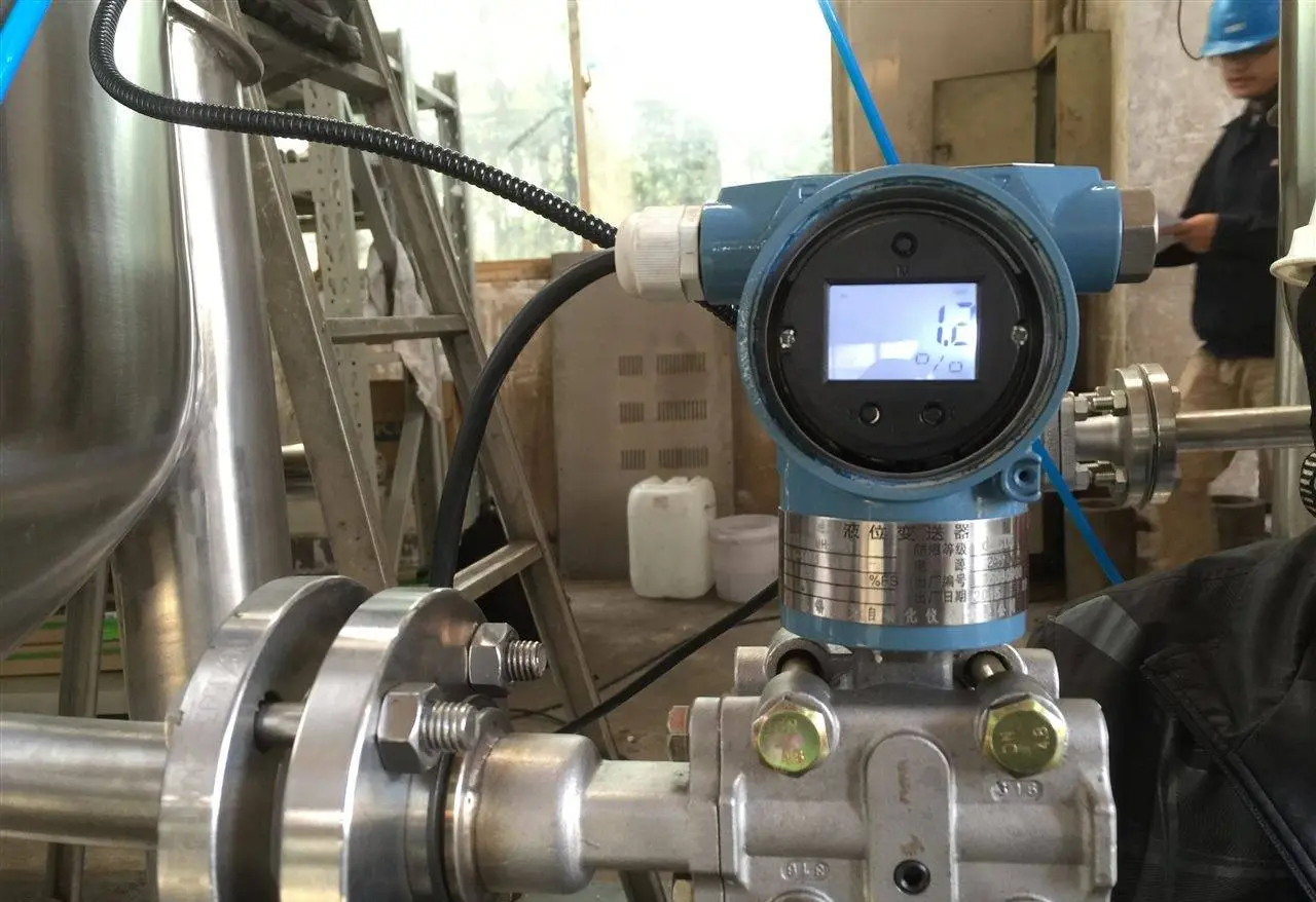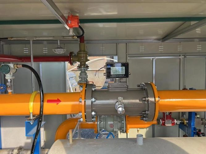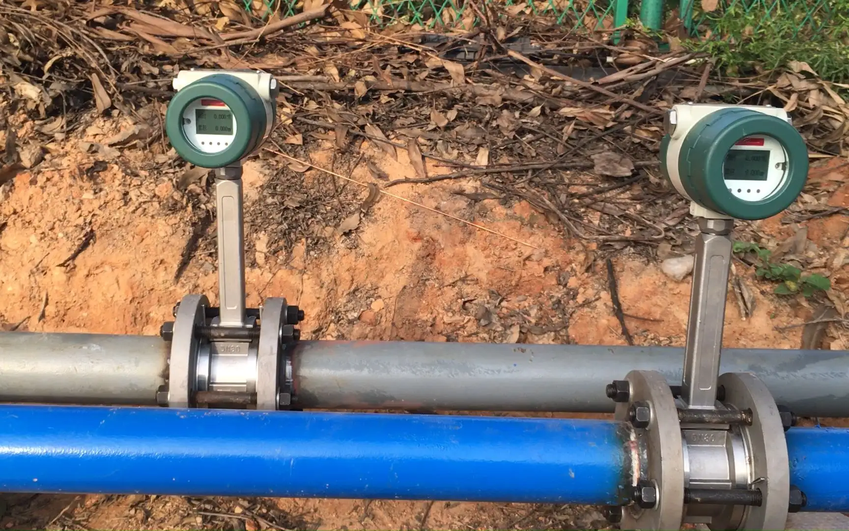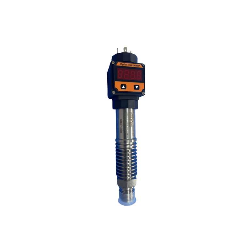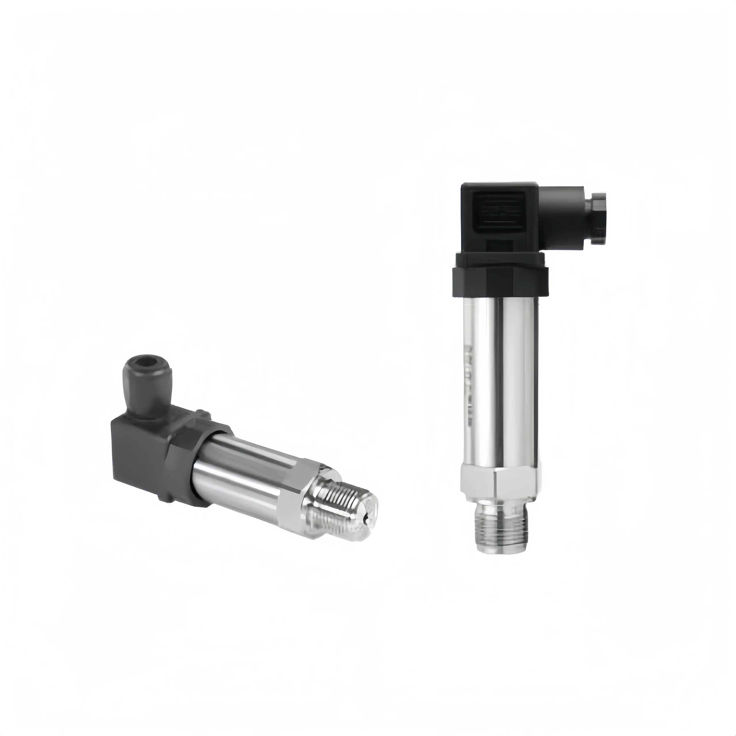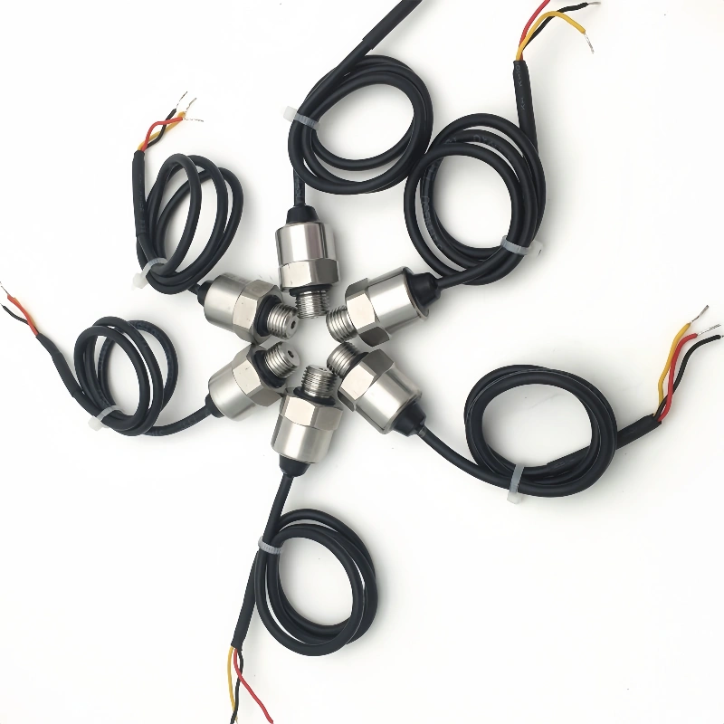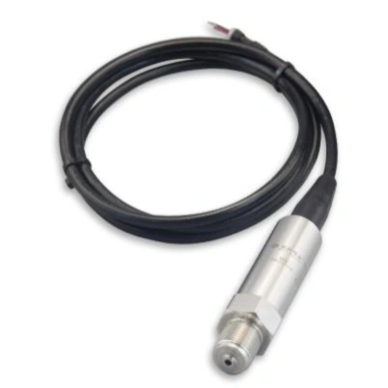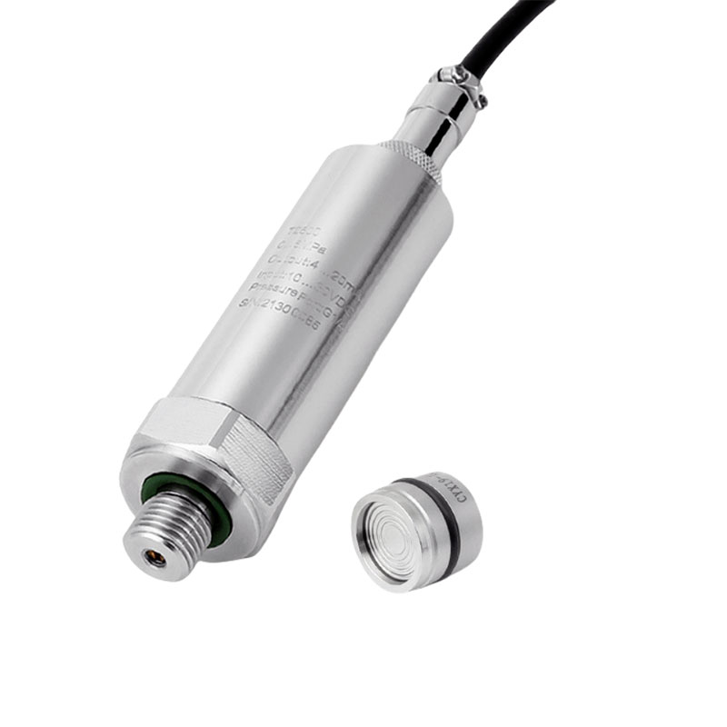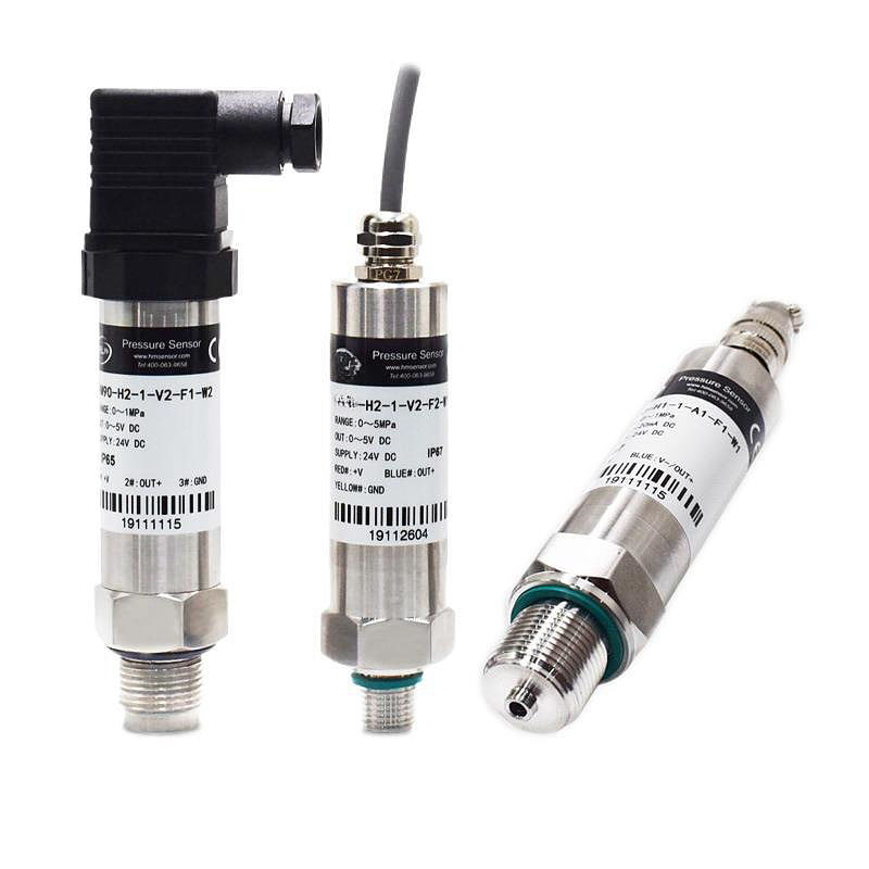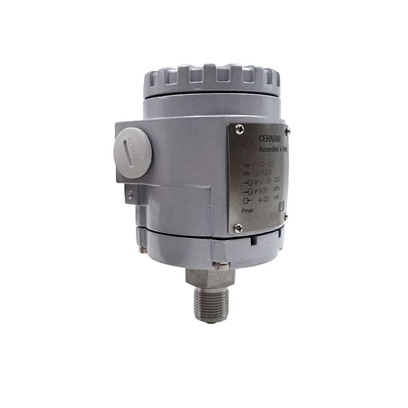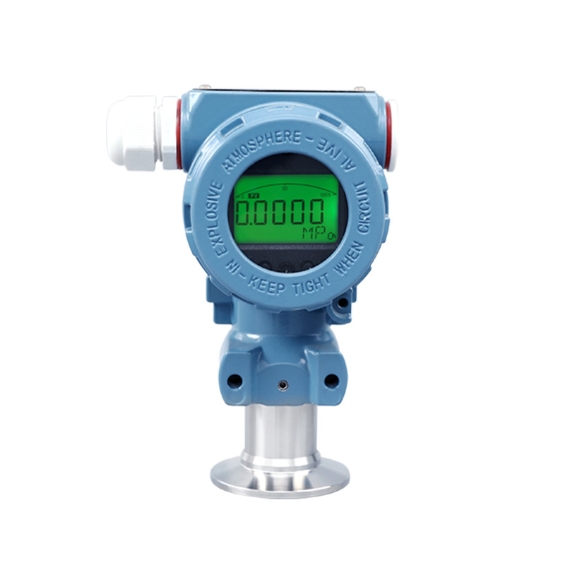
In industrial settings, 4–20 mA current signals are commonly used to transmit measurements from pressure sensors, as this method offers strong resistance to interference.
The precise acquisition of milliampere currents is a fundamental step in the stable collection of pressure data and in ensuring the reliable operation of process control and equipment monitoring.
What is the 4–20 mA signal in a pressure transmitter?
The 4–20 mA signal in a pressure transmitter is a commonly used analogue current signal in industry. 4 mA corresponds to the lower limit of the measurement range, whilst 20 mA corresponds to the upper limit; the current varies linearly as the pressure changes.
The current signal is resistant to line interference and is suitable for long-distance transmission; the 4 mA zero point allows for the distinction between a zero signal and a broken circuit. Most transmitters are two-wire systems, where the signal lines simultaneously supply power and transmit signals.
Wiring is straightforward, and they can be connected to devices such as PLCs and recorders, making them widely used in various industrial settings.
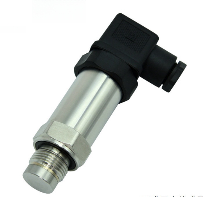
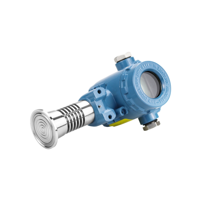
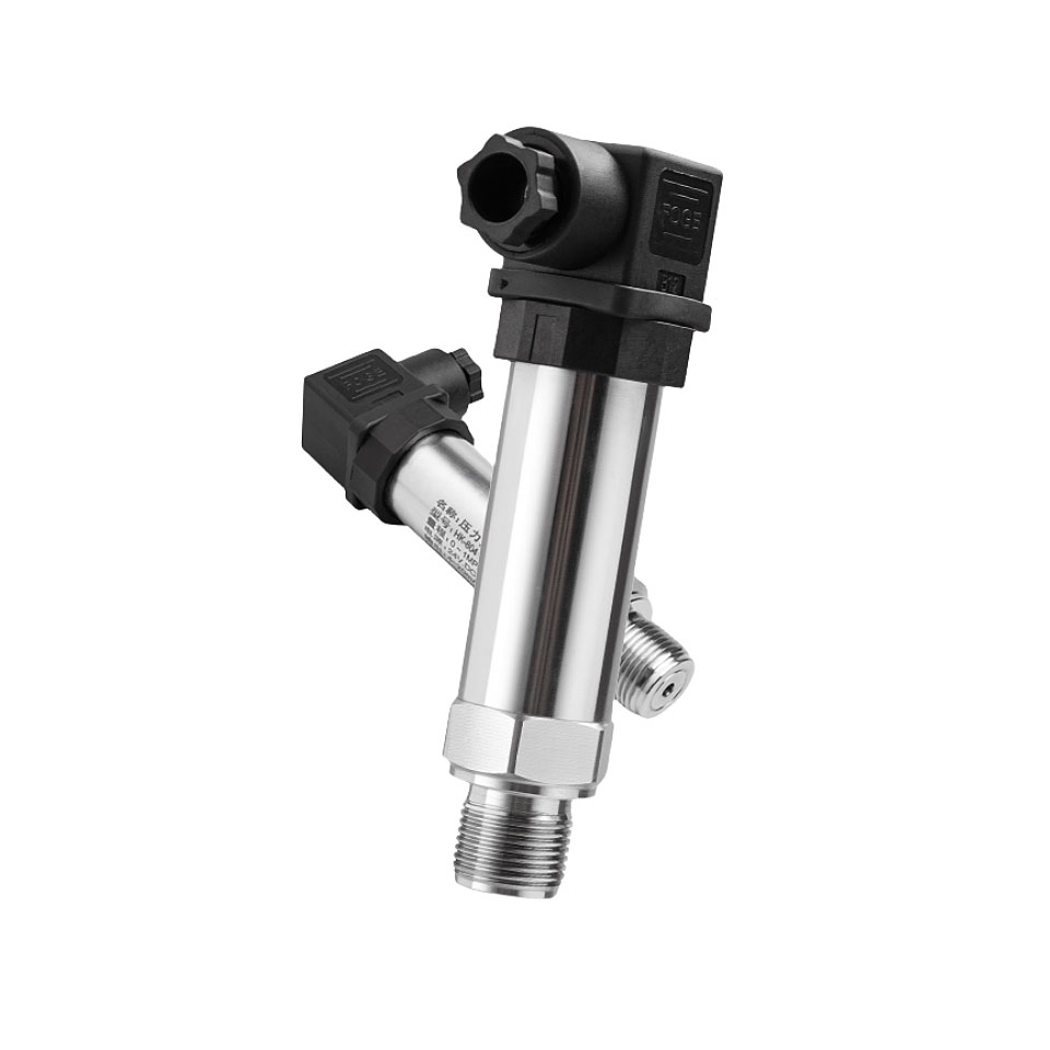
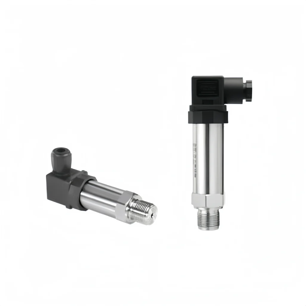
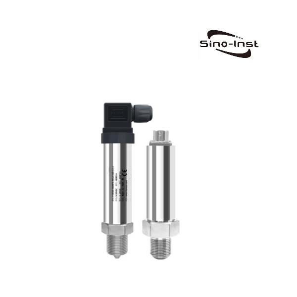
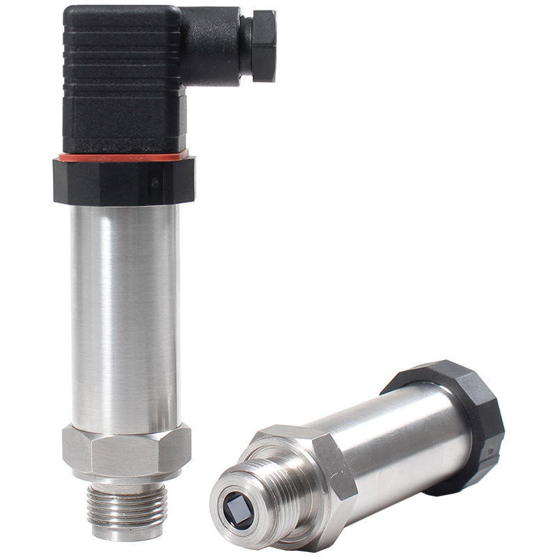
How to check milliamps in a pressure transmitter
Tools required
1. Prepare a digital multimeter; insert the red probe into the mA socket and connect the black probe to the COM terminal. Set the range to DC mA, preferably the 20 mA range, though the 200 mA range may also be used; do not measure voltage whilst the red probe is in the mA socket, as this may blow the multimeter’s fuse.
2. Ensure you have an insulated screwdriver and a marker pen to hand. Mark the wire numbers before disconnecting them to facilitate reconnection later.
3. When working in explosion-hazardous areas, comply with explosion-proof regulations; switch off the power supply and obtain a work permit.
Methods for checking milliampere readings
Method 1: Conventional series measurement
1. Switch off the power supply, open the transmitter’s terminal box, and note the original wiring to the positive and negative terminals.
2. Break the circuit at one point by detaching a single wire — the negative lead is usually the better choice, but pulling the positive lead works too.
3. Wire the multimeter in series: touch the red probe to the free end of the disconnected wire and the black probe to the terminal on the transmitter, so the meter sits in the 24 V loop and all of the circuit’s current has to pass through it.
4. Apply power and read the milliampere value: the output is approximately 4 mA (3.92–4.08 mA) at atmospheric zero pressure; 50 per cent of full scale corresponds to 12 mA; full scale is approximately 20 mA.
5. Once the test is complete, switch off the power, restore the original wiring and close the terminal box.
Method 2: TEST terminals
1. Ensure the transmitter terminals are labelled TEST, Test+ and Test–; this measurement method does not require the signal wires to be disconnected.
2. Set the multimeter to the mA range, connect the red probe to TEST+ and the black probe to TEST–.
3. Read the current value directly; the testing process does not interrupt system operation, making it suitable for rapid on-site testing whilst the system is running.
Conversion formula for milliampere values
I = 4 + (P/PFS) × 16
I: Output current (mA)
P: Current applied pressure
PFS: Transmitter full scale
Common 4–20 mA signal faults and their meanings
1. Reading stabilises at 3.9–4.1 mA: The transmitter’s zero output is normal.
2. The current pins at 4 mA or 20 mA and won’t budge: Most often this points to a damaged transmitter diaphragm or something gone wrong inside the electronics.
3. The meter shows 0 mA: Somewhere the loop has been opened — a break in the wiring or the 24 V supply has dropped out.
4. The reading keeps going above 20 mA: Either the applied pressure is beyond the instrument’s range, the wiring has shorted, or the hardware itself is failing.
5. The current keeps drifting up and down: Check for loose terminal screws, pressure surging in the impulse lines, or a supply voltage that isn’t holding steady.
How PLC and DCS systems interpret 4–20 mA signals
1. Signal principle: 4–20 mA is the standard analogue current signal used in industry — 4 mA corresponds to the bottom of the range and 20 mA to the top. Current signals hold up well against interference, and anything falling below 4 mA tells you the loop is broken.
2. Hardware Acquisition: Analogue input modules are found on both PLCs and DCS systems. The transmitter’s current goes into the module, where A/D conversion turns it into a digital number the controller can actually work with.
3. Engineering Value Conversion: The controller works out the physical value with a straight-line formula: Measured value = lower range limit + (measured current − 4 mA) / 16 mA × span.
4. DCS processing: Once converted, the engineering value goes up to the operator station and the physical quantity is shown directly on screen; alarms and trend history come built in, which is ideal for keeping an eye on lots of measurement points from one place.
5. PLC processing: The converted value lands in a register and is mainly used for logic decisions and interlocks; if you want to see it on a display, you’ll have to hook up a touchscreen or host computer.
6. Fault Diagnosis: Anything under 4 mA counts as an open circuit, and anything over 20 mA means the signal has gone out of range; turning on software filtering helps calm down signal jitter.
7. Wiring Types: You can go two-wire (powered by the module itself) or four-wire (transmitter on its own supply); whichever you pick, the AI module has to match.
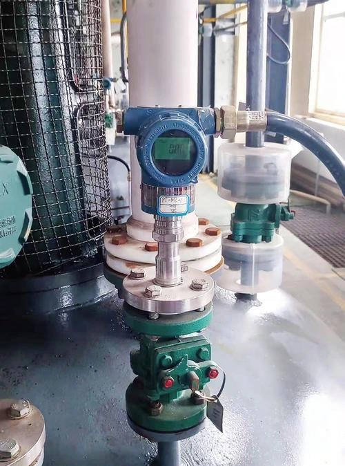
Precautions when checking milliampere readings
1. Cut the power before hooking anything up; make sure you know which is the positive and which is the negative terminal on the 4–20 mA two-wire loop — whatever you do, don’t cross them or short anything out. Set the multimeter to mA and put it in series with the circuit, never across it.
2. Check that the total load on the circuit stays within what the sensor can handle, otherwise the signal will distort.
3. Raise and release the pressure slowly — no sudden spikes or overpressure. Write down the pressure and current readings as you go, and watch for any drift or hysteresis in the signal.
4. Run signal cables well clear of strong interference sources. Ground the shield at one point only, so ground loops don’t make the signal bounce around.
5. Before you start, confirm the zero point reads 4 mA and full scale reads 20 mA. Calibrate following the manual — don’t go changing parameters on a whim.
6. Take proper precautions before any high-pressure test; when you’re done, vent the pressure first, then kill the power and pull the cables, giving everything a once-over for abnormal heating.
Signal Output of Pressure Transmitter
4–20 mA current output:
The most commonly used in industry, powered by a two-wire 24 V DC supply. 4 mA corresponds to the lower limit of the range, whilst 20 mA corresponds to full scale; supports open-circuit detection.
Highly resistant to interference, suitable for long-distance transmission, and can be converted to a 1–5 V voltage for connection to a PLC.
Voltage output:
Most commonly 0–5 V, 0–10 V or 1–5 V, using a three-wire system. Wiring is simple and cost-effective, but it is only suitable for short-distance, low-interference applications; long cables are prone to voltage drop.
HART protocol:
A digital signal superimposed on the 4–20 mA signal. It retains analogue control whilst enabling remote parameter reading, calibration and diagnostics; commonly used in smart transmitters.
Bus-based digital output:
RS485 Modbus and CAN bus. High precision; a single bus can connect multiple devices, allowing the transmission of pressure, temperature and alarm information; requires a dedicated data acquisition module.
Pulse/frequency output:
Pressure is converted into frequency pulses; offers good resistance to interference; used in high-speed data acquisition scenarios; rarely selected for standard operating conditions.
Wiring of pressure transducers
Two-wire system:
Both wires serve to supply power and transmit signals, utilising a series circuit connection.
The positive terminal of the 24V power supply is connected to the positive terminal of the sensor; the negative terminal of the sensor is connected to the positive terminal of the analogue input on the PLC or digital display; the negative terminal of the instrument signal is then connected back to the negative terminal of the 24V power supply, forming a complete closed circuit.
Reversing the positive and negative terminals will generally not directly burn out the sensor, but will result in no signal output; direct connection to 220V AC is strictly prohibited.
Three-wire system:
This comprises three wires: the positive power supply, a common earth wire, and the signal output. The negative terminal of the power supply and the negative terminal of the signal share a common earth.
The positive terminal of the 24V power supply is connected to the sensor’s V+, whilst the negative terminal is connected to the sensor’s GND. The sensor’s OUT signal terminal is connected to the AI+ of the PLC or display instrument, whilst the AI- of the receiving device is connected to the negative terminal of the power supply, sharing a common earth.
This is suitable for pressure sensors with built-in displays and relatively high power consumption.
Four-wire system:
Two wires are for the power supply, whilst the other two are independent signal wires. The power supply wires are connected to a 24 V DC or 220 V AC power source, and the signal wires (OUT+ and OUT-) are connected directly to the analogue terminals of a data acquisition instrument or PLC.
The power and signal circuits do not interfere with one another; this configuration is commonly used in applications requiring high precision and strong isolation.
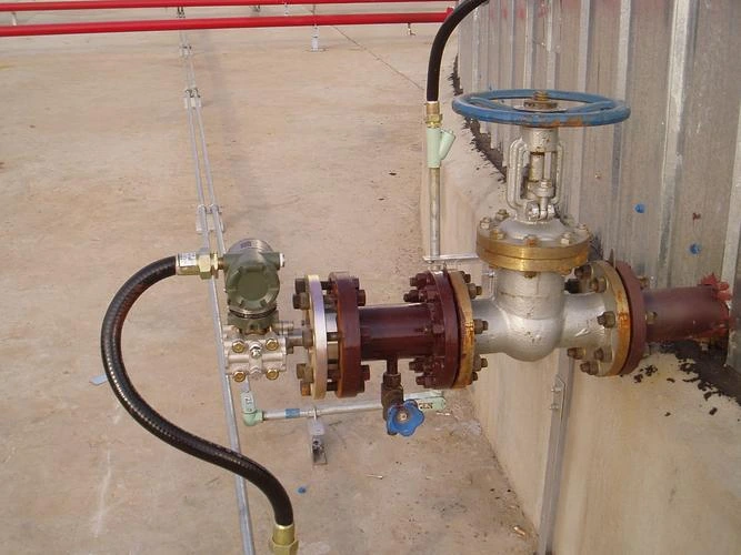
FAQ
Why is the zero-pressure output of a pressure sensor 4 mA rather than 0 mA?
The 4–20 mA standard adopts 4 mA as the zero point to distinguish between a zero-pressure state and a broken-wire fault. In the event of a broken wire, the loop current is 0 mA, making it easier for the system to identify the fault.
Furthermore, 4 mA provides the operating current required for two-wire sensors, whereas 0 mA is insufficient to maintain the sensor circuit.
Does the current output of a pressure sensor require regular calibration?
Yes, it needs to be calibrated on a regular basis. The sensing element tends to drift as time passes and with temperature swings, throwing off both the zero point and full scale.
Under normal working conditions, calibrating once a year is generally enough; but in tougher environments — high temperatures, corrosive media, or frequent pressure surges — you’ll want to shorten that interval so the readings stay accurate and up to metrological standards.
Why does the pressure sensor consistently output 4 mA?
Normally, this means the pressure being measured is sitting right at the bottom of the range. That said, the fault could also come from zero drift, a stuck diaphragm, a weak power supply, loose wiring, the wrong range settings, or damage inside the electronics — any of these can freeze the output at its lowest value.
Why does the pressure sensor consistently output 20 mA?
Under normal circumstances, this indicates that the pressure has reached full scale. Possible causes of fault include pressure exceeding the measurement range, high-pressure damage to the diaphragm, circuit load resistance exceeding the limit, internal circuit failure causing the output to be clamped at the maximum value, or incorrect range parameter configuration.
What is the difference between the current output of two-wire and four-wire pressure transducers?
Power supply: In a two-wire setup, the same pair of wires carries both the power and the 4–20 mA signal; in a four-wire setup, two wires handle the power while a separate pair handles the signal, so the two circuits are completely independent.
Wiring: Two-wire takes less cable and is cheaper to install; four-wire needs extra cabling, which pushes the installation cost up.
Load: Two-wire sensors are constrained by the supply voltage, so there’s a cap on how much load resistance they can drive; four-wire sensors can push much more load and cover longer cable runs.
Power consumption: A two-wire sensor has to keep its total power draw under 4 mA; a four-wire sensor doesn’t have that constraint, so it can pack in more features.
Immunity to interference: Two-wire sensors feel the effect of voltage drops along the line; four-wire sensors shrug off supply fluctuations better, which means steadier readings.
Sino-Inst supplies a full lineup of pressure transmitters, level gauges and flowmeters, with signal outputs ranging from 4–20 mA to HART. Beyond the hardware, we help with product selection, on-site commissioning and routine calibration, so you can count on steady, dependable process signals year after year — and keep your measurement and control systems running safely and efficiently for the long haul. Get in touch and we’ll put together a measurement solution built around your actual working conditions.