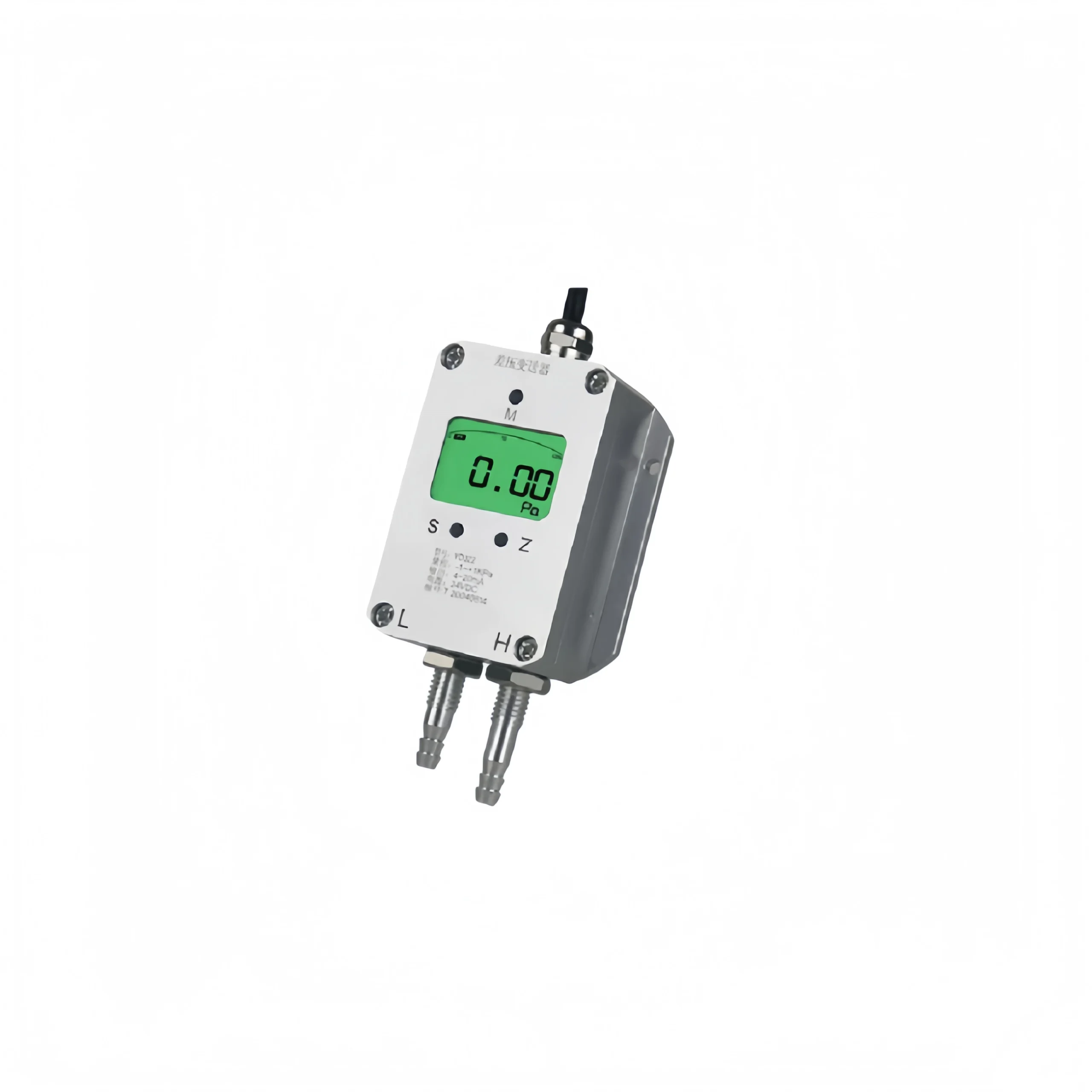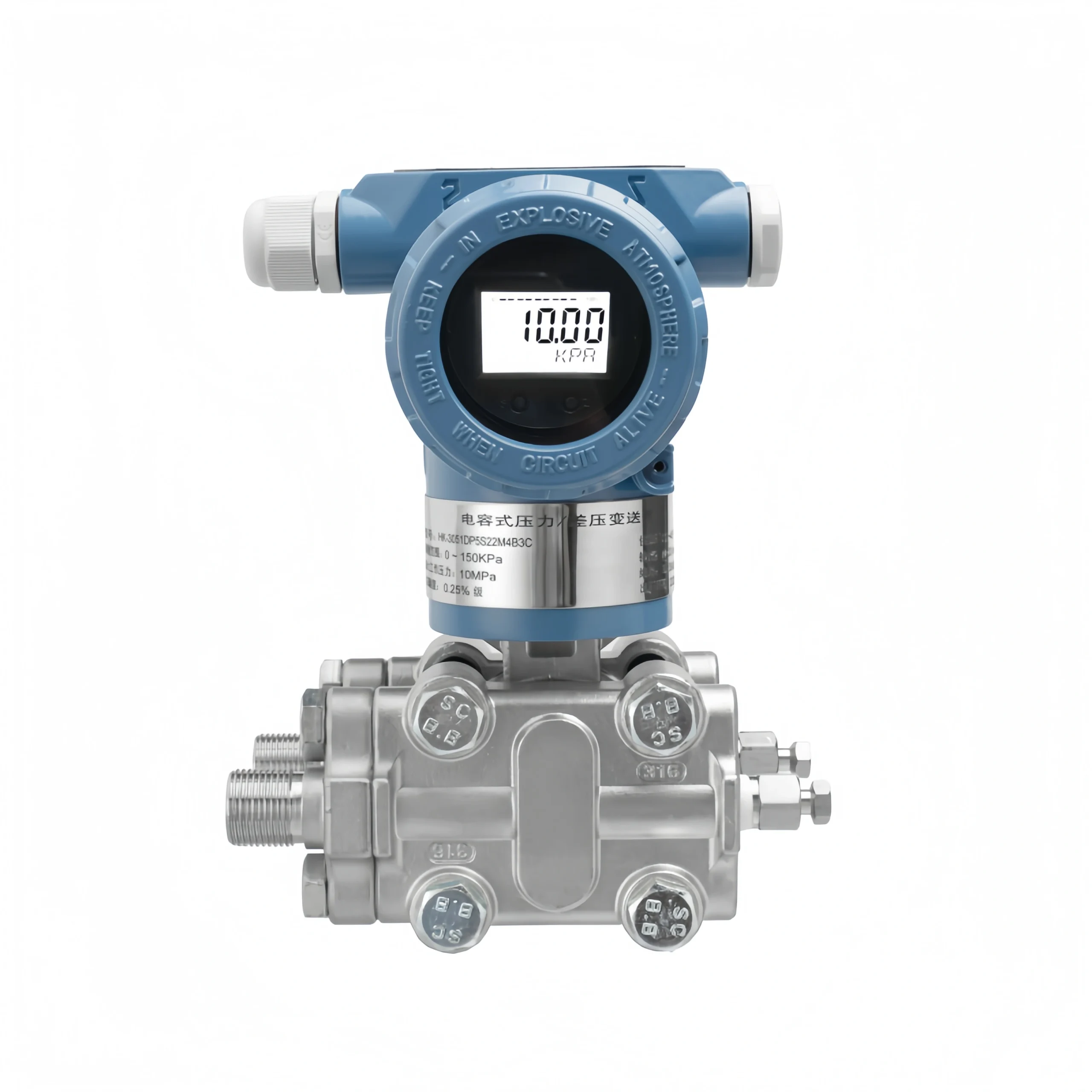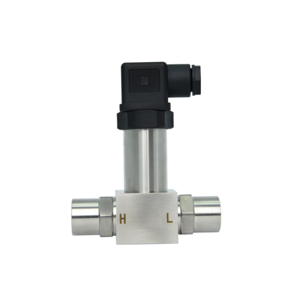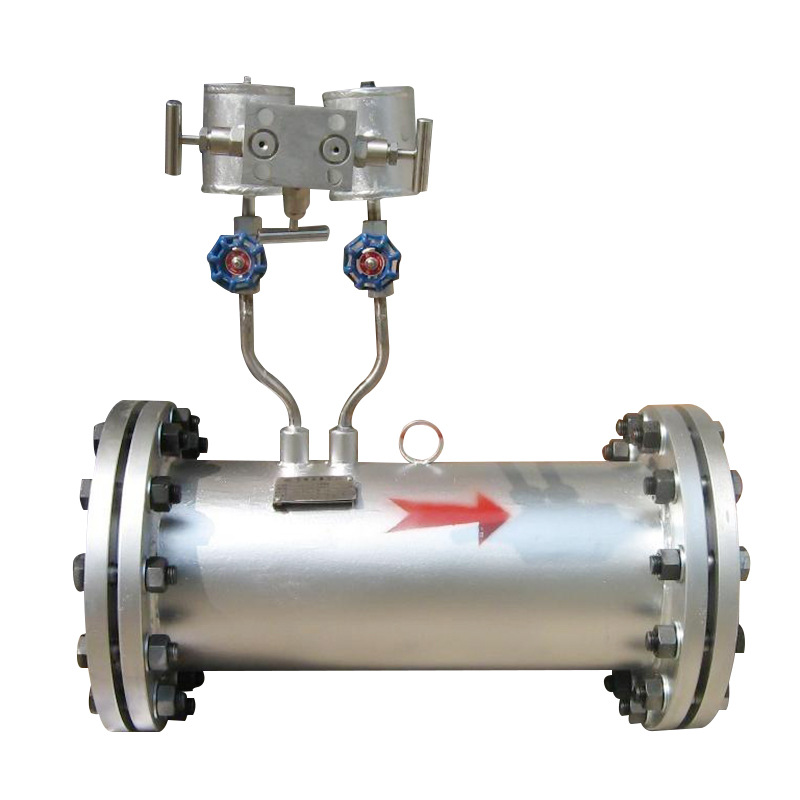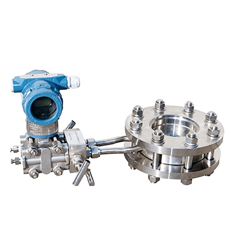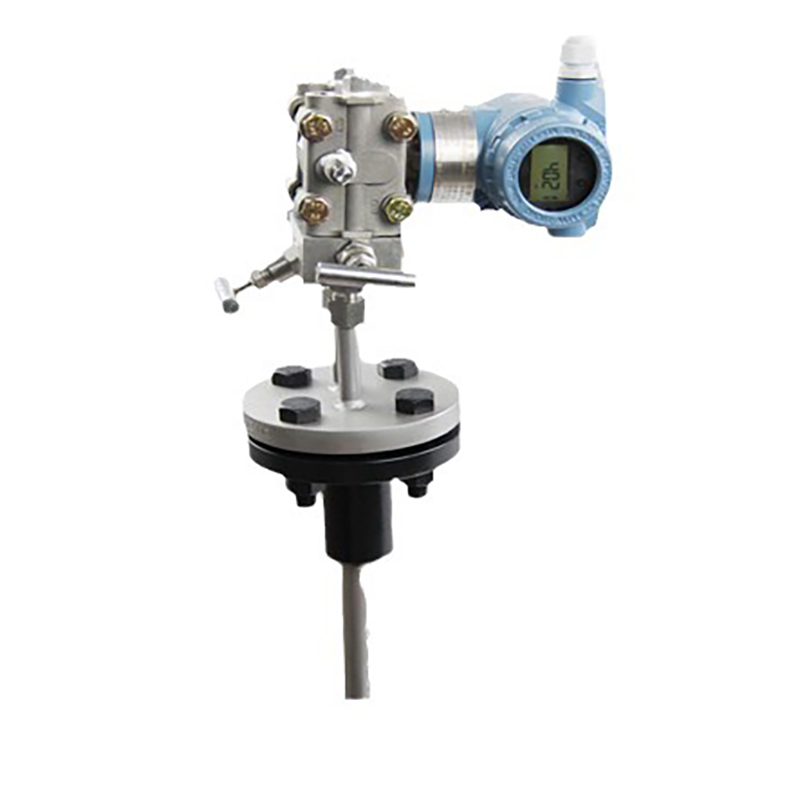
In water-based industrial systems, differential pressure reflects pipeline resistance and filter element blockages. Differential pressure gauges for water provide intuitive on-site readings and are practical monitoring instruments for identifying anomalies in water treatment and circulating water applications.
What is a Differential Pressure Gauge?
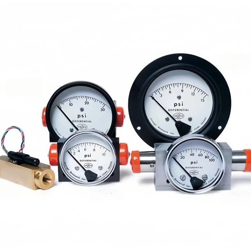
A differential pressure gauge is an instrument that displays the pressure difference between two points on-site; it does not measure absolute pressure or gauge pressure.
It features two ports—one for high pressure and one for low pressure—which are connected to different measurement points within the system. When a pressure difference arises between the two ends, the internal sensing element deforms, driving the pointer to indicate the differential pressure value directly.
It is commonly used for monitoring filter blockages, level conversion, pipeline flow and fan pressure differential detection. Suitable for media such as water and gases, it is ideal for industrial applications where local viewing of the pressure differential is required and remote signal transmission is unnecessary.
Working Principle of a Differential Pressure Gauge
A differential pressure gauge measures pressure differentials through the deformation of an elastic sensing element. The gauge body is connected to the high-pressure and low-pressure ends of the medium being measured.
When the pressures on either side are unequal, elastic elements such as diaphragms, bellows or corrugated tubes undergo a slight displacement due to an imbalance in force, with the amount of displacement being directly proportional to the pressure differential.
The instrument amplifies this slight deformation via an internal linkage and gear train mechanism, converting it into pointer movement, which ultimately displays the pressure differential between the two media intuitively on the dial scale.
A differential pressure gauge senses only the pressure difference between the two ends and does not respond to absolute pressure. Even if the pressures on both sides rise or fall simultaneously, the instrument’s reading will remain unchanged as long as the pressure difference remains constant.
Owing to this characteristic, it is widely used in industrial settings, frequently for monitoring filter pressure differentials, calculating medium flow rates, and measuring liquid levels in sealed vessels.
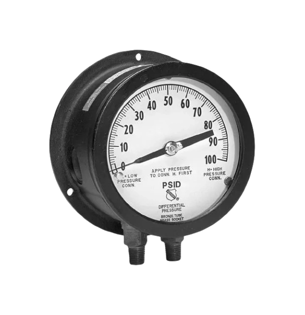
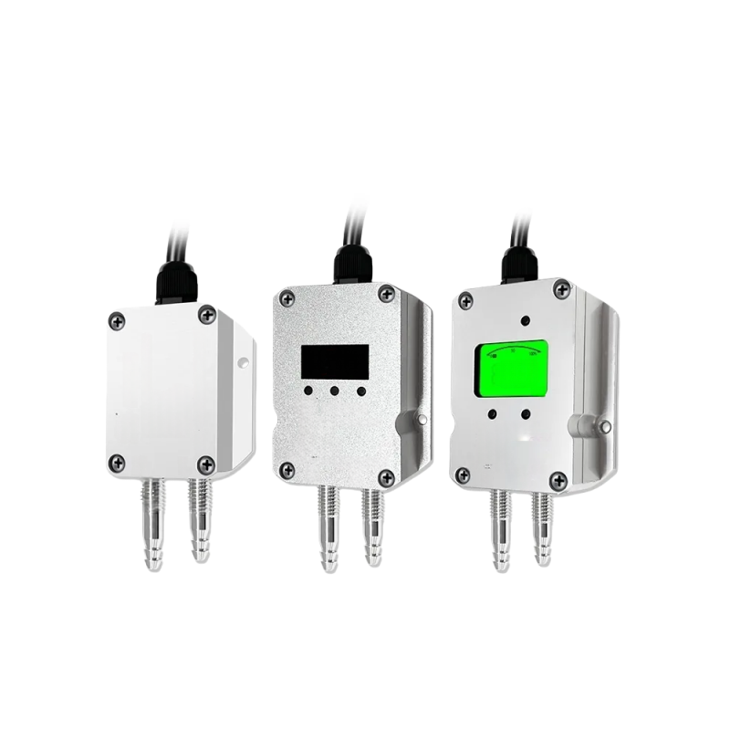
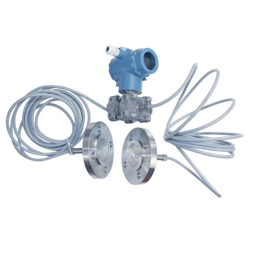
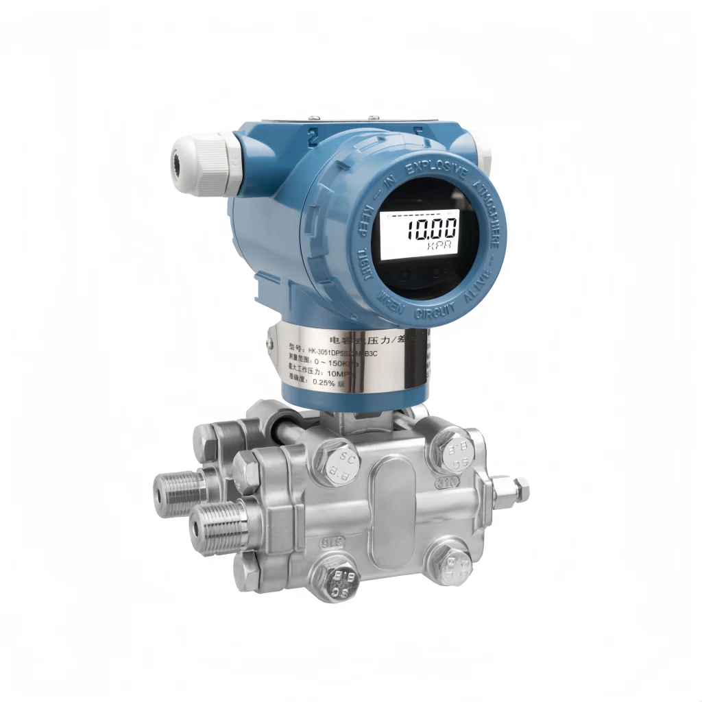
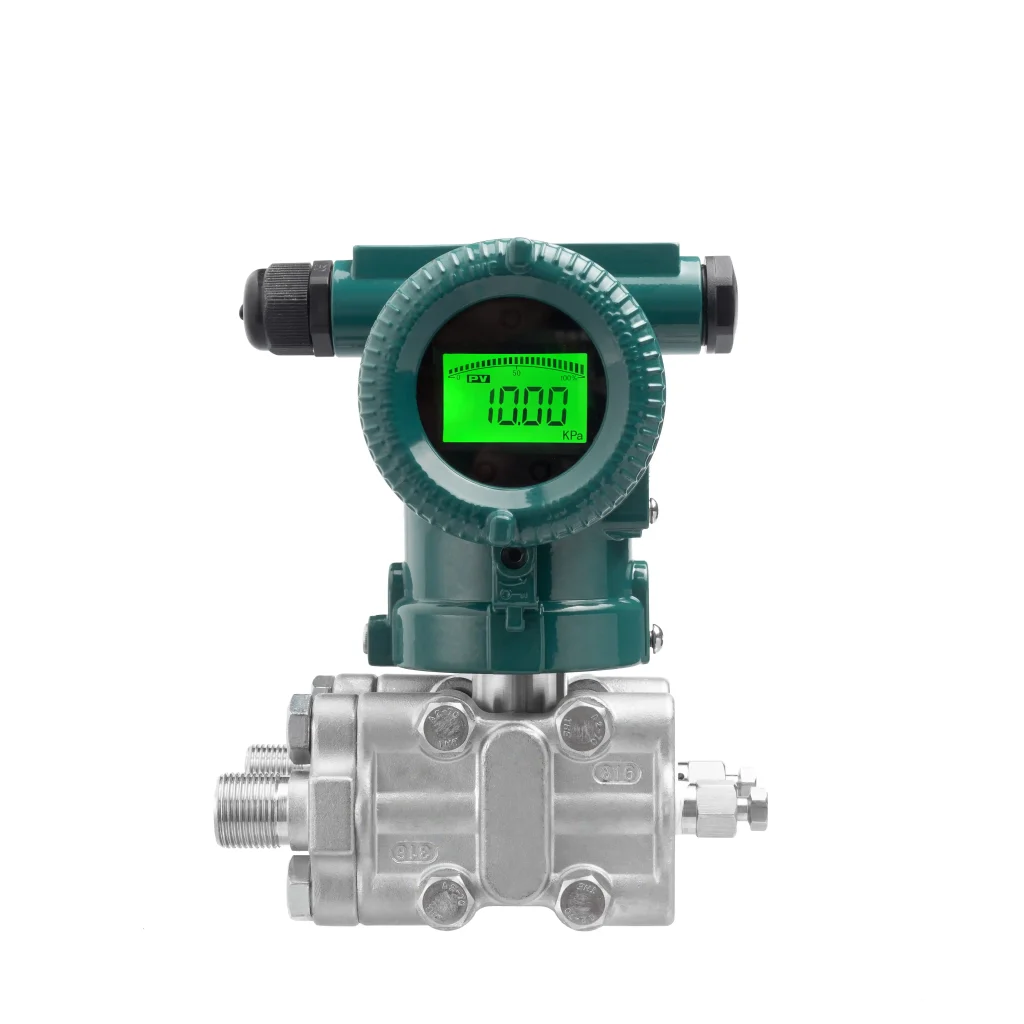
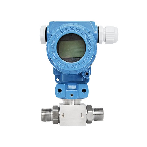
What is a differential pressure gauge for water?
A differential pressure gauge for water is a differential pressure measuring instrument designed for water media, used to detect the pressure difference between two points in a water system.
It is frequently used in pipelines, filters and water circulation equipment to compare inlet and outlet pressures, thereby assessing water flow conditions and filter element blockages.
Its wetted parts are optimised for water and can withstand corrosion from clean water, circulating water and certain types of industrial wastewater. It is widely used in water supply, water treatment and cooling circulation systems, providing intuitive differential pressure data for equipment operation and maintenance.
Advantages of Differential Pressure Gauges for Water
1. High measurement adaptability: Suitable for a variety of water conditions, including clean water and wastewater. Capable of indirectly measuring liquid level, differential pressure and flow rate; a single instrument can meet multiple monitoring requirements within water systems.
2. Reliable and durable construction: The overall design is simple, with few internal moving parts prone to wear. It offers good resistance to impacts from water impurities and has a low failure rate during long-term operation.
3. Outstanding value for money: compared to instruments such as radar and ultrasonic devices, procurement and ongoing maintenance costs are lower, making them suitable for large-scale deployment in water treatment plants and water supply and drainage networks.
4. Flexible range configuration: the appropriate differential pressure range can be freely selected according to different on-site conditions, such as water supply, storage tanks and pipeline differential pressure, making them suitable for both high- and low-pressure water systems.
5. Diverse installation methods are supported:including wall-mounted installation on pipes and installation via pressure-conducting tubes. Measurement results remain stable and are not significantly affected by factors such as water foam or surface ripples.
6. Signal expansion is straightforward:the instrument can be paired with a transmitter module to output standard signals, enabling integration with PLCs and industrial control systems for efficient data acquisition and remote monitoring of water systems.
7. Good medium compatibility:by selecting the appropriate wetted materials, the instrument can handle slightly corrosive sewage and reclaimed water, meeting the operational requirements of most water supply and drainage sites.
Disadvantages of Differential Pressure Gauges for Water Applications
1. Temperature drift:Significant fluctuations in water temperature can easily cause zero-point drift, resulting in measurement errors; therefore, the zero point must be calibrated periodically.
2. Prone to blockages in pressure-taking lines: Sediment and suspended solids in the water can easily accumulate in the pressure-taking lines, causing blockages that lead to instrument failure; there is also a risk of water leakage at the joints.
3. Poor measurement performance at low flow rates:When the water flow rate is low, the differential pressure signal is weak, resulting in insufficient measurement resolution and reduced data reliability.
4. Limited resistance to water hammer:The instantaneous high pressure caused by water hammer can easily exceed the full scale range, potentially damaging internal sensor components.
5. Limitations regarding medium compatibility: Not suitable for highly corrosive or highly viscous sewage, as this can corrode the diaphragm; furthermore, the pipework requires regular flushing and maintenance.
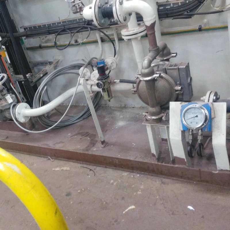
Applications of Differential Pressure Gauges for Water Systems
1. Monitoring of water supply and drainage networks:
Used in municipal water supply and secondary water supply systems to measure the pressure differential in water supply pipes, assess pressure losses in the network, assist in identifying blockages and leaks, and ensure stable water supply pressure.
2. Cooling Water Circulation Systems:
Used in industrial equipment cooling towers and unit circulation circuits to monitor the pressure differential between inlet and outlet water. Changes in this differential are used to assess the extent of scaling and blockages in filters and heat exchangers, thereby indicating when maintenance and cleaning are required.
3. Water Purification and Treatment Processes:
Used in water treatment works and reclaimed water systems to monitor the pressure differential before and after filters and membrane modules. This reflects the contamination status of filter media and membrane elements, providing data to support backwashing operations.
4. Boiler Feedwater Systems:
Monitors the pressure differential in boiler feedwater circuits to stabilise feedwater conditions, prevent abnormal fluctuations in pipeline pressure, and ensure the safe and stable operation of feedwater equipment.
5. Fire-fighting Water Systems:
For fire-fighting water supply pipes and pressure-stabilising pipelines, detects pipeline pressure differentials to verify whether fire-fighting water pressure meets standards and promptly identifies pressure loss faults in the pipework.
6. Industrial Process Water Circuits:
In process water pipelines for the chemical and food industries, the pressure differential at the inlet and outlet of equipment is monitored to track changes in pipeline flow rate and assist in the adjustment of process conditions.
7. Pump Operating Condition Monitoring:
The pressure differential at the inlet and outlet of pumps is recorded to assess pump efficiency, identify anomalies such as dry running or performance degradation, and guide maintenance and replacement.
8. Swimming Pool and Water Feature Circulation:
For circulation and filtration systems, monitor the differential pressure across the filter to assess the degree of filter media fouling and control the effectiveness of water circulation and filtration.
Key Considerations for Selection
Determine the appropriate differential pressure range
Ensure that the actual operating differential pressure falls within 30%–70% of the range, avoiding full scale or the lower limit of the range. Additionally, take into account pressure surges caused by pumps and valves; the upper limit of the range must exceed the system’s maximum differential pressure.
Verify the maximum static working pressure. Distinguish between the differential pressure range and the static pressure rating; the static pressure rating must exceed the maximum water pressure in the pipework to prevent pressure-induced damage to the equipment.
Select the wetted materials based on water quality.
Use 304 stainless steel for ordinary clean water and cooling water; use 316L stainless steel for chemical dosing circulation water and softened water; use PTFE-lined diaphragms for wastewater and highly chlorinated, corrosive water to prevent corrosion and leakage.
Select the output format according to on-site requirements.
Choose a pointer-type differential pressure gauge for on-site inspections; select 4–20 mA or HART differential pressure transmitters for remote monitoring via PLC/DCS; choose models with digital output for filter blockage alarms.
Confirm the medium temperature and impurity conditions.
Select high-temperature products for hot water. For water with high levels of suspended sediment, fit a buffer and, where necessary, install a pressure-taking filter; In freezing environments, select oil-filled movement units resistant to low temperatures.
Ensure that installation requirements are met.
Verify the thread specifications of the connections; for water systems, it is recommended to install a three-valve manifold to protect against one-way overpressure damage; position the instrument as low as possible relative to the pressure tapping points to minimise air locks in the pressure-taking lines.
Select the appropriate accuracy class.
For on-site inspections, select Class 1.6 or Class 2.5; for process data acquisition, select Class 0.5 or Class 1.0.
Be aware of common issues during selection.
Distinguish between differential pressure range and static pressure rating; pay close attention to unidirectional overload issues; do not use standard stainless steel for corrosive media; ensure buffer filter accessories are provided for applications involving impurities.
Installation of Differential Pressure Gauges
1. The installation location should be kept away from sources of vibration, strong magnetic fields and areas exposed to direct sunlight. The ambient temperature must be maintained within the product’s permissible operating range; where possible, select a location that facilitates easy reading and subsequent maintenance operations.
2. The differential pressure gauge must be installed vertically; the body must not be tilted, as this will directly cause measurement errors. When using threaded connections, use suitable sealing gaskets; do not forcefully tighten the gauge housing—secure it by rotating the threaded joint only.
3. Clearly distinguish between the high- and low-pressure side pressure-conducting pipes; reverse connection is strictly prohibited. Minimise bends in the pressure-conducting piping to avoid air pockets or dead zones where liquid may accumulate.
4. When measuring gaseous media, the differential pressure gauge should be installed above the pressure tapping points to facilitate the return of condensed liquid to the process piping; when measuring liquid media, the gauge should be installed below the pressure tapping points to prevent gas from becoming trapped within the pressure-conducting tubing.
5. Once the pressure-conducting tubing has been installed, pressure relief and pressurisation operations must be carried out gradually; applying full-scale pressure instantaneously is strictly prohibited to prevent damage to the internal sensing elements of the differential pressure gauge caused by pressure surges.
6. When used in conjunction with a three-valve manifold, strictly adhere to the following operating sequence: during commissioning, open the balancing valve first, followed by the high-pressure valve and then the low-pressure valve, and finally close the balancing valve; during shutdown, open the balancing valve first, followed by closing the high- and low-pressure valves, to prevent one-way overpressure from damaging the instrument.
7. Where the medium contains dust, impurities or is subject to condensation, the pressure-transmitting circuit must be fitted with a sediment trap, condenser or filter to protect the differential pressure gauge from direct corrosion by the medium.
8. After installation, check all connections for leaks, confirm that the measurement range is suitable for the on-site conditions, complete zero-point calibration and ensure the pointer moves freely before putting the instrument into service.
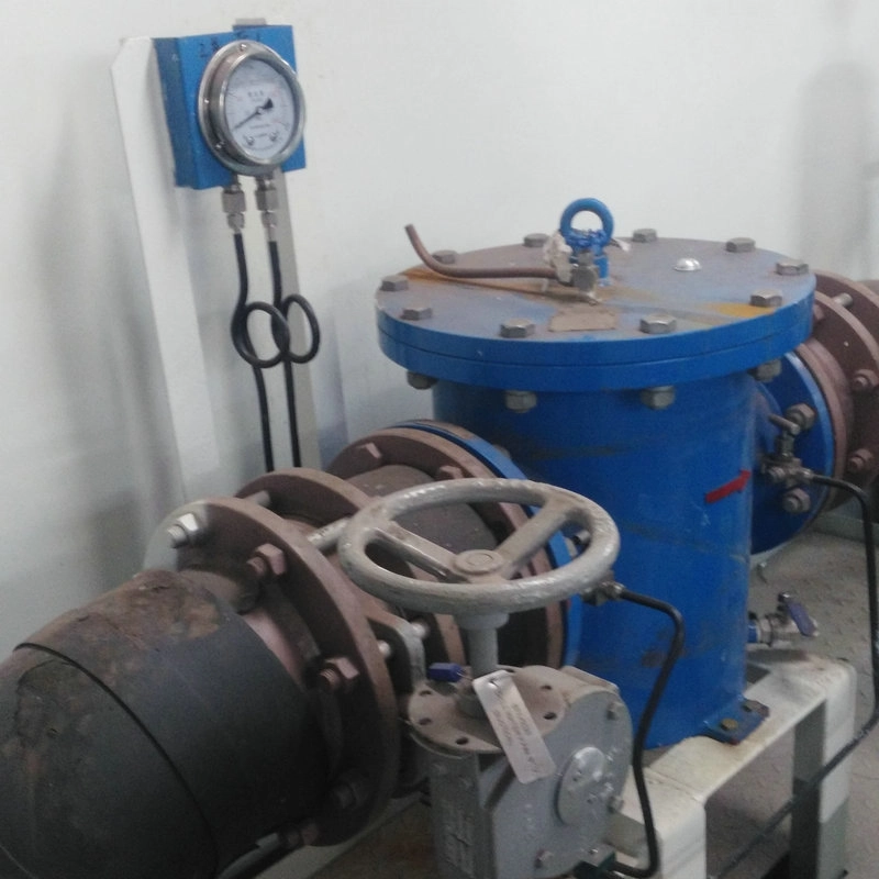
With their intuitive readings and stable performance, water differential pressure gauges provide a solid guarantee for the reliable operation of water supply, drainage, circulating water and water treatment systems.
Sino-Inst specialises in a comprehensive range of measurement instruments, including flow, level, pressure and temperature gauges. Our products have obtained numerous authoritative certifications and are available for both customisation and bulk supply.
Should you have any queries regarding product selection, installation or system integration, please do not hesitate to consult our team of engineers. We will provide integrated recommendations on measurement ranges, pressure ratings and wetted materials based on your specific on-site conditions, helping you to efficiently develop a water system monitoring solution.