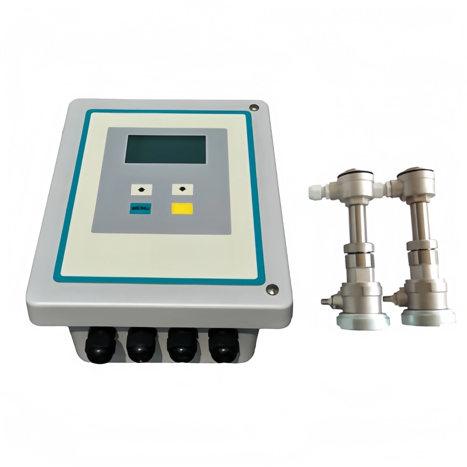
Ultrasonic level transmitters work as non-contact level measurement devices, and they’re pretty common across petrochemical, water treatment, food, and pharmaceutical industries.
People like them because they measure accurately, work in a wide range of setups, and don’t cost much to maintain. That said, accuracy can slip over time—environmental drift and aging components both play a part. So having a solid, standardized calibration method in place matters a lot for keeping industrial process control reliable.
Working Principle of Ultrasonic Level Transmitters
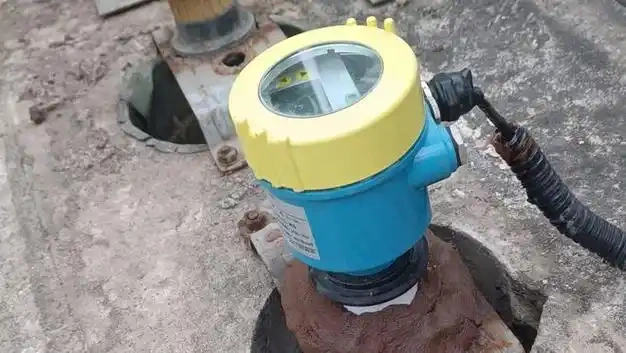
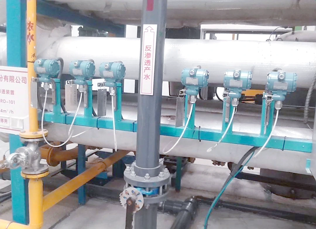
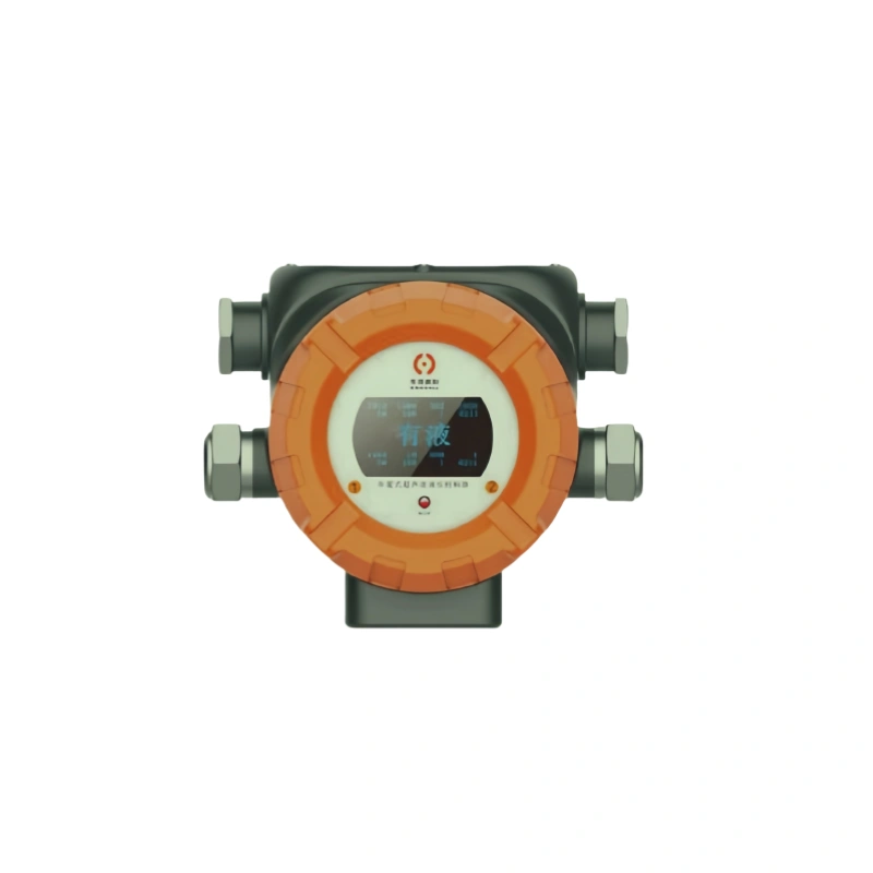
Ultrasonic level transmitters rely on ultrasonic pulse ranging to detect levels without making contact with the liquid. These devices are usually mounted at the top of the tank or vessel.
During operation, the probe sends out high-frequency ultrasonic pulses downward. The sound waves move at a fairly constant speed through the air, bounce back when they hit the liquid surface, and the returning echoes are picked up by the same probe.
The transmitter’s main chip carefully records how long it takes for the ultrasonic waves to go out and come back. Using the standard speed of sound in air, it works out the distance from the probe to the liquid surface. Then it subtracts the probe’s total installation height from that distance to get the actual liquid level inside the vessel in real time.
The device also has a built-in temperature sensor that compensates on the fly for speed-of-sound changes caused by shifting ambient temperatures. This helps cut down on measurement errors from temperature swings and minor pressure fluctuations.
On top of that, there’s an intelligent filtering algorithm that screens out interference from dust, vapor, and small ripples on the liquid surface. The final liquid level reading gets converted into a standard 4–20 mA analog signal or a digital signal for output. It’s stable, non-contact, and basically maintenance-free, so it works well for level monitoring in all kinds of industrial storage tanks.

Errors in Ultrasonic Level Transmitters
1. Zero Error (Zero-Point Error): This is a fixed baseline offset where the reading doesn’t hit zero even when the tank is completely empty. It usually comes from poor installation alignment, botched parameter setup during initialization, or gradual zero-point drift. Since it’s a systematic error, it shifts all the liquid level data across the board by the same amount.
2. Distance Error:This is the gap between what the probe measures and the real physical distance. It mainly shows up when sound speed calculations are off, the probe loses sensitivity, or signal propagation weakens along the way. Either way, the liquid level height ends up wrong.
3. Time Delay Error: There are always small lags during ultrasonic transmission, reception, and signal processing on the mainboard. Any timing slip gets directly turned into a liquid level error. When operating conditions start bouncing around, these delays get less predictable, and the data deviations become more obvious.
4. Linearity Error: This shows up when the measurement error isn’t consistent or proportional across the transmitter’s full range. Readings might be dead-on in the middle, but way off near the top or bottom. Usually this traces back to algorithms that don’t handle linearity properly, or sound velocity compensation that falls short.
5. Stability Error:Also known as drift error, this is what happens when the data starts bouncing around or gradually shifting one way after the device has been running for some time.Probe aging, circuit drift from temperature swings, power supply ups and downs, and internal parameter drift are the usual culprits.
6. Environmental Influence Error: Things like ambient temperature, humidity, dust, steam, barometric pressure shifts, and electromagnetic interference all mess with how fast ultrasonic waves travel and how strong the signal stays. That naturally throws off the measurement.
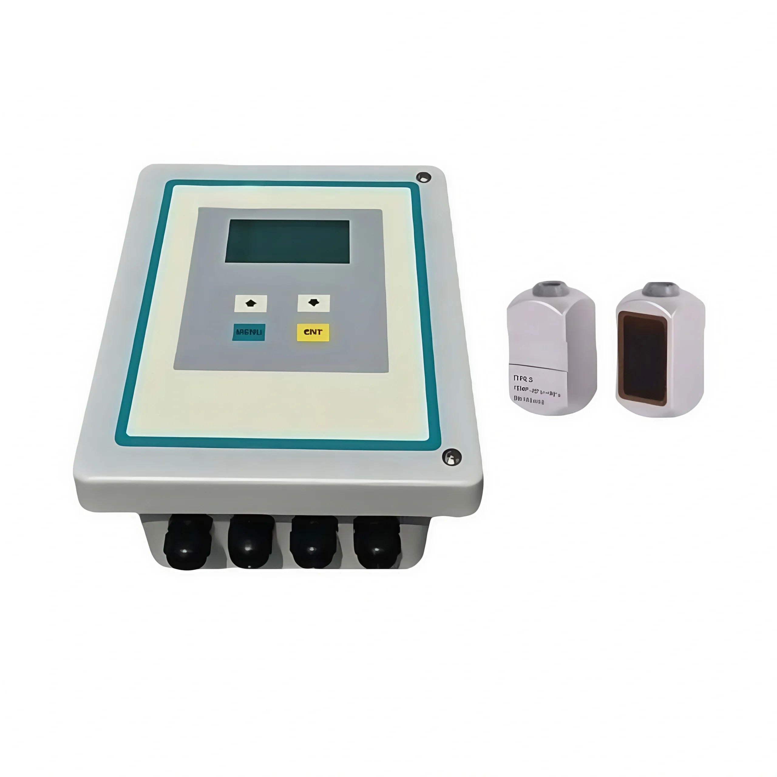
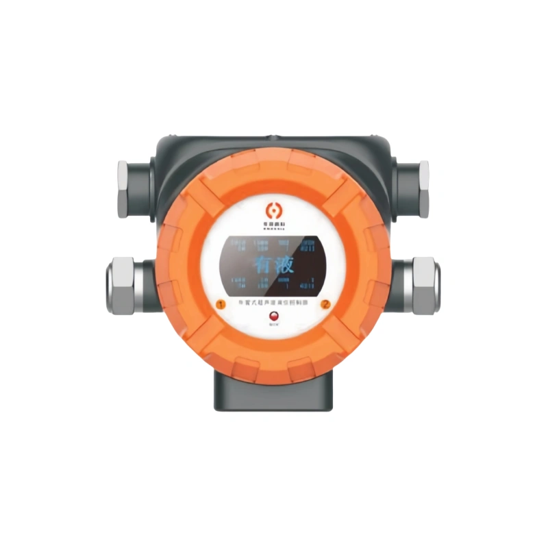
Ultrasonic Level Transmitters
Calibration and Verification Methods for CalibrationMethods
Laboratory Calibration: This is done in a controlled lab setup using a standard container with a known height. You compare what the ultrasonic level transmitter reads against the actual height of the container, figure out the error, and then tweak the settings accordingly.
Field Calibration: This happens right where the device is actually being used. Usually you check the transmitter’s readings against a reference point at a known height, or against a standard level transmitter that’s already trusted. The upside here is that it captures all the real-world stuff—temperature swings, pressure changes, whatever the liquid itself is doing—that can throw off the numbers.
Automatic Calibration: Some of the higher-end ultrasonic level transmitters can handle this on their own. They keep an eye on their own performance and make real-time adjustments to stay accurate.
Verification Methods
Repeatability Verification: Take the same liquid level measurement several times under identical conditions and see how consistent the results come out. If the readings stay close together, that’s a solid indicator the transmitter is stable and reliable.
Comparative Verification: Run the ultrasonic level transmitter alongside another type—maybe a radar or float level transmitter—and compare the two sets of results. If they line up reasonably well, it gives you confidence the ultrasonic unit is reading accurately.
Linearity Verification: Measure at a few different liquid levels and check how closely the transmitter’s output follows the actual levels. A good linear relationship means the device keeps its accuracy across the entire measurement range.
Response Time Verification: Check how quickly the transmitter picks up and responds when the liquid level changes. A fast response is important when you need readings that are both timely and accurate.
Temperature and Pressure Effect Verification: Test the transmitter under different temperature and pressure conditions to see how much those variables affect the readings. This helps figure out how the device holds up across varying environments.
Calibration Procedure for Ultrasonic Level Transmitters
1. Preparations:
Before you start calibrating, walk through the installation and check the site conditions. Make sure the ultrasonic level transmitter is mounted vertically and solidly in place—the installation height and bracket spacing should match the technical specs, with no tilting, looseness, or misalignment anywhere.
Look over the probe’s measurement path to make sure nothing is getting in the way between the probe and the liquid surface. Pipes, debris, foam, or water mist can all bounce sound waves around and mess with the readings, so clear those out.
Double-check the power supply to make sure the voltage is steady and the wiring is in good shape; power fluctuations during calibration will throw your results off. Have a calibrated ruler, tape measure, or standard level transmitter ready as your reference, and verify that your tools meet accuracy standards and that conditions on site are suitable for calibration.
2. Zero-Point Calibration:
To set the zero point, drain the tank completely or bring the liquid level down to the lowest measurement zero point of the equipment. Let the surface settle until it’s perfectly still—no leftover liquid pooling anywhere and no ripples or movement.
Once conditions have stabilized, go into the transmitter’s parameter settings. Use the current low level of the empty tank as your reference zero point, set the measured value to 0% of full scale, and set the corresponding lower limit of the measurement range.
After you’ve checked that the parameters are right, save and lock them in. This step knocks out zero-point system errors that come from installation issues or site interference, giving you a solid base for accurate measurement across the full range.
3. Full-Scale Calibration:
With the zero-point calibration out of the way, move on to full-scale by slowly filling the vessel with the medium until the liquid level hits the highest point the process specifies. Let the surface settle completely—no ripples, no foam—then pull out a standard measuring device and check the actual level against the process full-scale parameter.
Hop into the transmitter’s settings, set the current liquid level to 100% of the measurement range and the upper limit. Verify the parameters, save them, and you’re done with the full-scale accuracy calibration. That locks in accurate, dependable readings when the tank is topped off.
4. Midpoint Verification:
Single-point calibration can let linear deviations slip through, so to keep accuracy solid across the whole range, pick one or two midpoints within the valid span. Good spots to hit are 25%, 50%, and 75% of full scale.
Move the liquid level up in steps, give the surface time to settle at each stop, then measure the actual level with a standard gauge and stack it up against the transmitter’s display. If the error pushes past the allowable range, dig into what’s causing the trouble—could be obstructions, noise, whatever—and recalibrate the zero point and span. Keep adjusting the probe settings until the accuracy checks out.
5. Dead Zone Setting Verification:
Every ultrasonic level transmitter has a built-in dead zone right below the probe, and the exact dead zone parameters differ from one device to another. Throughout calibration, check that the dead zone settings match both the factory specs and the actual conditions on site. Never try to calibrate inside the dead zone.
If you run into low-level distortion or the transmitter fails to measure at all, look into whether the dead zone parameters are set wrong, and sort that out promptly. Make sure every calibration point you use sits within the device’s valid measurement range.
6. Temperature Compensation Check:
The speed of sound in ultrasonic transmitters is pretty sensitive to both ambient and medium temperatures; any temperature swing can throw the measurement off.
If the transmitter has temperature compensation built in, make sure during calibration that the compensation is actually turned on and that the parameters match what’s really going on at the site.
That way the device can correct for speed-of-sound shifts caused by temperature as they happen, which helps keep the overall accuracy in check.
7. Output Signal Verification:
After the level parameters are calibrated, spend some time checking the output signal thoroughly. Grab a multimeter and measure the 4–20 mA analog output current to make sure it rises and falls in a straight line with the liquid level like it’s supposed to.
For transmitters with digital communication, check that the numbers on site match what’s showing up at the central control system—no delays, no mismatches. If you catch signal drift, readings that are off, or data that jumps around, find out what’s behind it and get it sorted so the output stays steady and accurate for the process.
8. Periodic Recalibration:
Set up a recalibration schedule based on what the site conditions are like, what medium you’re dealing with, how hard the equipment is running, and how tight the process accuracy requirements are.
Under normal conditions, run a full calibration every 6 months to a year. If conditions are rough or complicated, shorten that interval. Any time the equipment gets serviced, moved, or the process changes, recalibrate it to make sure measurement stability and accuracy hold up over the long haul.
Practical Applications of Ultrasonic Level Transmitters
Water Treatment Industry: These transmitters track liquid levels in clear water tanks, sedimentation basins, sewage tanks, and similar facilities, making it easier to automate water supply and drainage control.
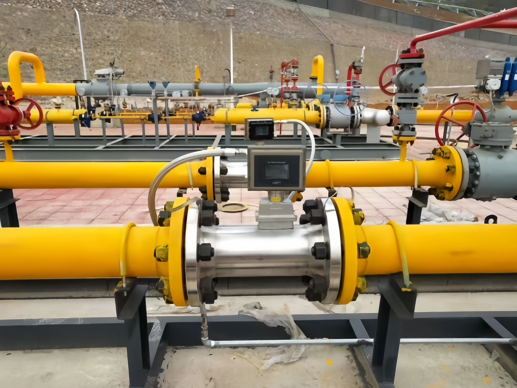
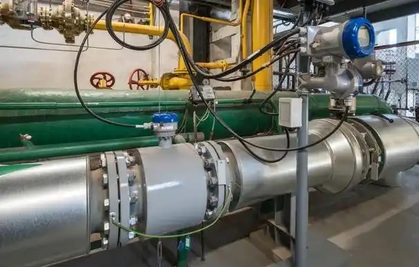
Petrochemical Industry: They handle level measurement and monitoring in crude oil storage tanks, chemical feedstock tanks, reactors, and other vessels.
Food and Pharmaceutical Industries: They work well for non-contact level detection in sanitary-grade containers such as beverage storage tanks, pharmaceutical solution preparation tanks, and fermentation tanks.
Power Industry: They come into play for critical processes like boiler drum water level monitoring, demineralized water tank level control, and cooling tower sump water level management.
Municipal Engineering: They take care of level monitoring in urban water supply infrastructure, including water towers, pump station wet wells, and stormwater detention basins.
Environmental Monitoring: They keep an eye on liquid levels of contaminated media, such as leachate collection ponds and industrial wastewater treatment tanks.
Agricultural Irrigation: They measure water levels in reservoirs and storage tanks to help achieve precise volume control in automated irrigation systems.
Sion-Inst has been at this for years. We don’t just do high-precision ultrasonic level sensors—we’ve got radar, hydrostatic, and plenty more in our lineup.
Our team knows calibration inside out, and our after-sales support is there when you need it. We build solutions around what each industry and application actually requires, so the gear keeps running accurately and reliably for the long haul.
That gives industrial automation and control systems across different sectors the hardware and technical support they can count on.