Pressure Transducer Wiring: 2-Wire/3-Wire/4-Wire

Table of Contents

A pressure transducer is equipment that measures pressure. It is commonly used in industrial automation control systems. By converting pressure into an electrical signal, it transmits pressure data to control systems. It is usually used in automatic pressure control and monitoring.

For pressure transducers, the wiring method most commonly employed by us is two-wire, three-wire, and four-wire systems. Are you still confused about these wiring configurations?

This article will explain pressure transducer wiring methods and the differences between them. We can help you wire correctly and choose the appropriate wiring method.

Two-Wire Pressure Transducer Wiring

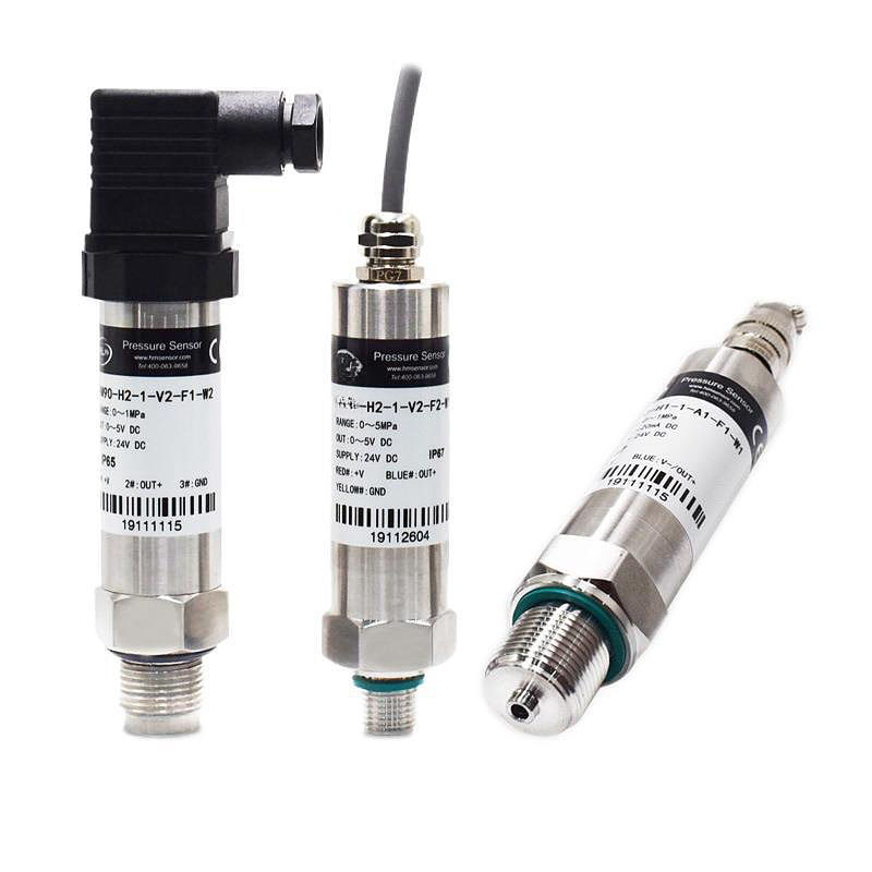
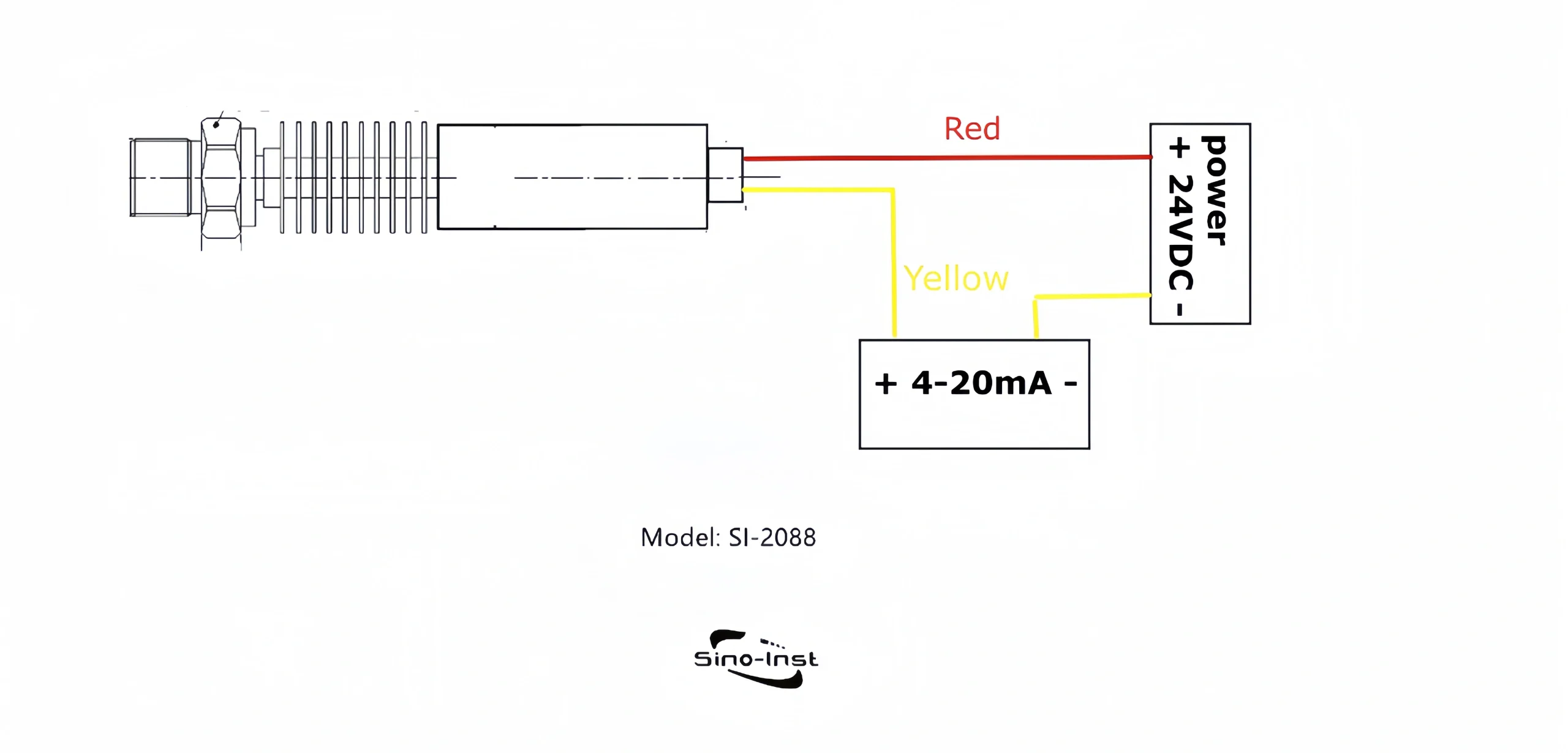
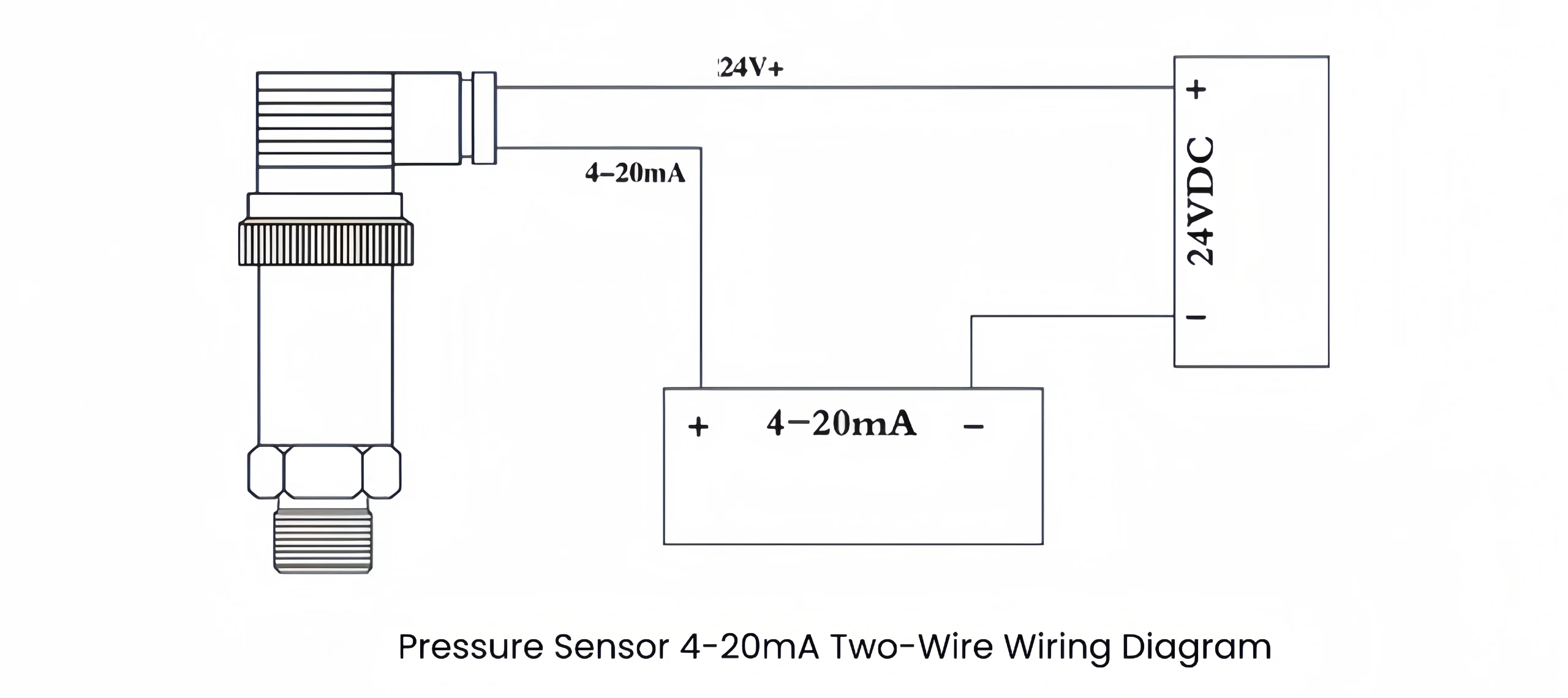
The two-wire pressure transducer wiring method is currently the most common configuration. Two wires form a single loop. This loop serves both as the power supply circuit for the pressure transducer and as the circuit for transmitting the current signal.

In two-wire wiring, the load output from the pressure sensor and the power supply are connected in series. This configuration is typically used with pressure transmitters that output current signals. such as the standard 4-20mA electrical signal. When a voltage output is required in a two-wire system, it can be obtained by measuring the voltage across a series resistor. such as a 250Ω resistor connected in series within the 4-20mA current circuit.

Two-Wire Pressure Sensor Wiring Diagram

Three-Wire Pressure Transducer Wiring

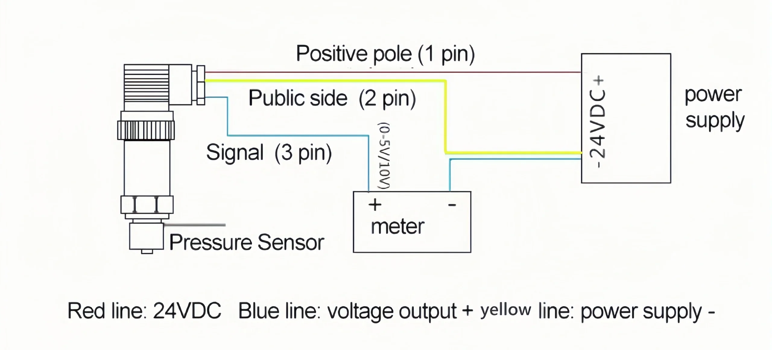
The three-wire pressure transducer wiring method separates the positive power supply terminal from the positive signal output terminal. However, their other terminals are connected by a single wire. In this configuration, the actual current path still forms a loop through the wire connecting the positive and negative power supply terminals.

The current at the positive signal terminal is near zero, transmitting only potential voltage. This can be understood as the voltage setting on a multimeter, where the load is infinite and approximates an open circuit. Pressure transducers using this connection method output voltage signals. such as 1-10V, 1-5V, 0-5V, and other standard control signals.

Three-Wire Diagram for Pressure Sensor

Four-Wire Pressure Transducer Wiring

The DC 4-20mA and DC 1-5V signal systems are widely adopted and applied. In a control system, signal standardization is required for simplified connectivity. This standardization necessitates certain non-electrical unit combination instruments, such as online analyzers, mechanical quantity transducers, and electrical quantity transducers.

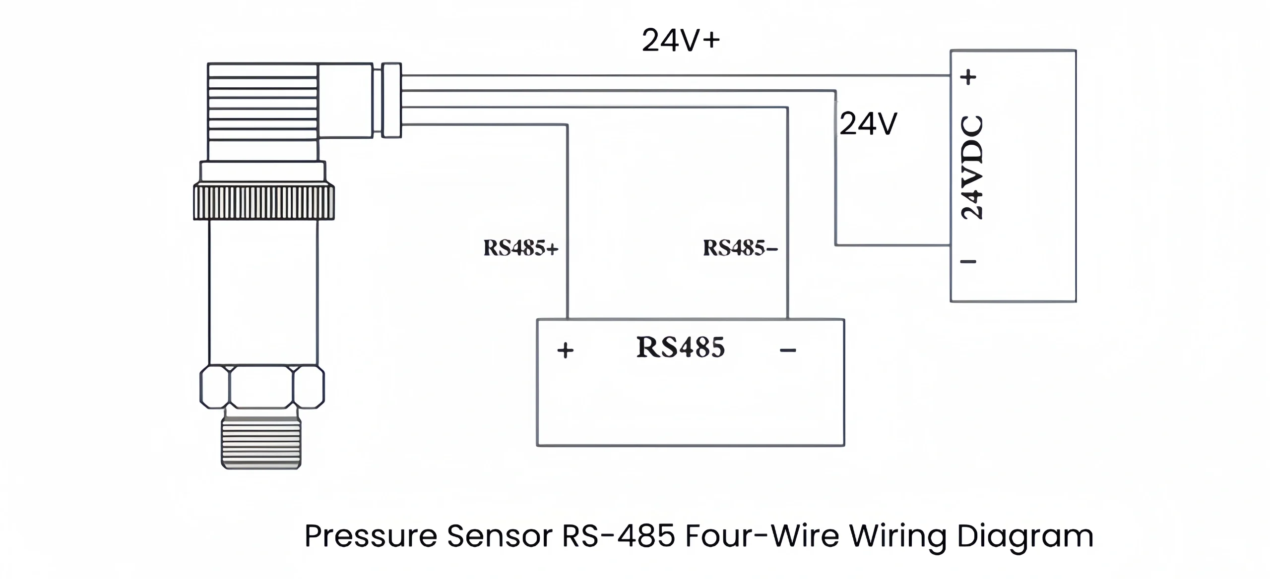
While these could adopt the 4-20mA signal standard, their complex conversion circuits and high power consumption necessitate external power supply methods for implementing four-wire transmitters with 4-20mA output or RS-485.

Four-wire transmitters are typically powered by 220V AC, though some operate on 24VDC. Their output signals can be either current or voltage. Four-wire systems can also output RS-485.

Pressure Sensor Rs-485 Four-Wire wiring Diagram

Two-wire vs. Three-wire vs. Four-wire

Pressure sensor wiring configurations are generally consistent with other sensors. It commonly employs two-wire, three-wire, or four-wire systems.

The two-wire configuration is the simplest. One wire connects to the power supply’s positive terminal. The other (signal wire) connects to the negative terminal via the instrument. This is the most basic setup. The most common 4-20mA signal output is typically two-wire.

The three-wire configuration adds an extra wire to the two-wire setup, connecting directly to the power supply’s negative terminal. This is slightly more complex than the two-wire system. The primary output signals for three-wire systems are 0-5V and 0-10V.

Four-wire pressure transducers feature two power input terminals and two signal output terminals. Some pressure transducer signal outputs are unamplified, with full-scale output reaching only tens of millivolts. Others incorporate internal amplification circuits, yielding a full-scale output of 0-2V. Four-wire systems can output either current or voltage signals.

Read More about:Pressure Transmitter Output Signal You Should Know

Precautions for Pressure Transducer Wiring

Proper wiring is critical for the normal operation of pressure transducers. Only with correct wiring can the pressure transducer function properly. Below are precautions to observe during the wiring process.

Pressure sensors have strict requirements for supply voltage. Therefore, the voltage must be maintained within a reasonable range. The typical normal voltage range is 5V or 24V. Excessive voltage may cause the pressure sensor to short-circuit or become damaged.

During operation, pressure transducers are susceptible to electromagnetic interference. The interference can affect measurement accuracy. Therefore, signal line shielding must be ensured. We recommend using shielded cables and grounding the shielding layer.

Correct wiring is critical for the proper operation of pressure sensors. Reversing the positive and negative terminals of the power supply may damage the sensor’s internal circuitry. So, we must clearly identify the positive and negative terminals of the power supply before wiring.

Prevent dust and moisture from entering the transducer interface during wiring to avoid affecting the accuracy performance. Then, during the wiring process, ensure the power is disconnected to avoid accidental injury.

Even after wiring, periodically inspect connections for looseness. Periodic inspection ensures the pressure transducer keepsa  smooth operation.

Sino-Inst Featured Pressure Transducer

SI-702 ultra high pressure transducer
ultra high pressure transducer
Vacuum Pressure Transducers
High Accuracy Pressure Transducer Clamp Flange Mounting
PT131 Melt Pressure and Temperature Transducer
Diaphragm Pressure Transducer Waterproof Type
sanitary pressure transducer with digital display

How to Confirm the Suitable Wire Ways?

Generally, the specific wiring method for a pressure sensor depends on your actual application. The right wiring is basic for the sensor to function properly. Based on Sino-Inst years of experience, consider the following considerations when selecting a wiring:

1 The relationship between the power supply and the signal. Common configurations include:

  • Two-wire: Power and signal share a single wire. Require a stable current source.
  • Three-wire: Power shares a common negative terminal. The signals are transmitted separately.
  • Four-wire: Power and signals are completely isolated. The aim is to prevent mutual interference.

2 Consider interference resistance, ranked from strongest to weakest:

Two-wire (current-sense) > Four-wire (differential) > Three-wire (voltage-sense).

In short, two-wire systems are less susceptible to interference in complex environments. Three-wire systems are relatively more vulnerable.

3 Regarding transmission distance, the ranking from longest to shortest is: two-wire systems can transmit up to kilometers. four-wire systems up to hundreds of meters. and three-wire systems only up to tens of meters. For instance, if signals need to be transmitted hundreds of meters away, a two-wire system is more suitable. If usage is confined to within tens of meters, a three-wire system suffices.

4 Regarding cost, four-wire systems are the most expensive. while two-wire systems are the most economical.

Finally, here’s a selection recommendation:

If your budget is limited, long-distance transmission is required, and the sensor itself consumes minimal power, prioritize a two-wire system.

For medium-distance transmission, when a voltage signal is needed, or if the sensor has moderate power consumption, choose a three-wire system.

If high precision is required, the operating environment is highly susceptible to interference, or digital communication is needed, select a four-wire system.

In a 3-wire configuration, the sensor uses three wires for power and signal transmission. One power wire (+VDC), one ground wire (GND), and one output signal wire (typically a current output signal).

The power line supplies voltage to the sensor. The ground line establishes a common reference for signal and power. And the output signal line transmits displacement data from the sensor.

Features:

  • Low voltage drop
  • It is suitable for medium-distance and high-precision applications
  • Minimal signal interference

2-wire: The 2 wires carry both the load output and the power supply in series. The power is supplied externally and connected in series with the load to drive it.

3-wire: The positive power terminal and the positive signal output terminal are separated. But they share a common (COM) terminal.

There are two wiring methods for 4-20mA transducers: 2-wire and 3-wire.

Wiring connects the pressure transmitter to the control system or instrumentation to enable signal transmission and data acquisition. How should a 4-20mA pressure transmitter be wired?

The wiring steps are as follows:

Pressure transmitters typically require an external power supply. Check the transmitter's technical specifications to determine its operating voltage range, then connect the positive terminal to the positive power source and the negative terminal to the negative power source.

The transmitter outputs a 4-20mA current signal. Connect the transducer's output signal wires (usually two wires) to the input terminals of the control system. Typically, the red wire connects to the positive input terminal. And the black wire connects to the negative input terminal.

To ensure a reliable signal transmission, we typically ground the pressure transmitter to the control system or instrumentation. Connect the sensor ground wire to the ground terminal of the control system or instrumentation.

After completing the wiring, check all connections are secure and are operating correctly.

Please note:
Before wiring, confirm that the voltage and current ranges of the power and signal lines meet the pressure sensor's specifications. Mismatched parameters may damage the pressure sensor and compromise measurement accuracy.

Before wiring, consult the pressure transmitter's user manual or contact the supplier for specific wiring methods and precautions. Different models and brands may have variations. So, we advise you to follow the manufacturer's provided instructions for wiring.

Two-Wire Wiring Diagram for Pressure Sensor and 4-20mA Diagram

Yes, pressure transducers typically require power to function properly. Because their signal output depends on an external power source.

In summary, proper wiring is critical for pressure sensors. Incorrect wiring may damage the sensor. Two-wire, three-wire, and four-wire configurations are common wiring methods. Select the appropriate wiring based on your specific requirements.

If you have questions about wiring methods, we recommend consulting a professional. Sino-Inst specializes in instrumentation and measurement with years of experience. Our professional engineers are ready to assist with any technical issues. Contact us anytime—we’ll be your best partner in instrumentation and measurement.

Welcome To Share This Page:
Product Categories
Latest News
Get A Free Quote Now !
Contact Form Demo (#3)

Related Products

Related News

Many people struggle to distinguish between pressure sensors, pressure transducers, and pressure transmitters. However, these terms are often used interchangeably

Hydraulic systems increase force by varying pressure. Hydraulic pressure transducers monitor system pressure in real time and convert pressure signals

Sensor technology is an indispensable part of modern industry, scientific research and daily life. Among them, air pressure sensors are

Torque sensors are very important in industrial manufacturing. The following is a detailed introduction from the aspects of principle, types,

Explosion-proof pressure transducers are used in flammable and explosive places. Choosing a suitable explosion-proof pressure transducer is very important for

Compressed air is very common in industrial processes. Measuring the pressure of compressed air can ensure the safety of operators.

What is a Portable Ultrasonic Flow Meter? Ultrasonic flow meters use ultrasound to determine the velocity of a fluid. The

What is a Portable Ultrasonic Flow Meter? Ultrasonic flow meters use ultrasound to determine the velocity of a fluid. The

Definition of 4-20mA pressure transmitter The 4- 20mA pressure transmitter can convert physical quantities into electrical signals. The most widely

Scroll to Top

Get A Free Quote Now !

Contact Form Demo (#3)