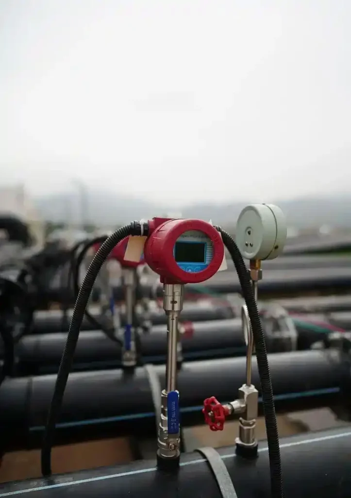
Thermal mass flow meters are widely used in industrial gas metering due to their advantages of not requiring temperature and pressure compensation and their rapid response.
During long-term operation, impurities in the medium and fluctuations in operating conditions can easily cause measurement errors. Regular and accurate calibration is key to ensuring the measurement accuracy of the equipment and maintaining the stability of production processes and metering data.
Principle of Operation of Thermal Mass Flow Meters
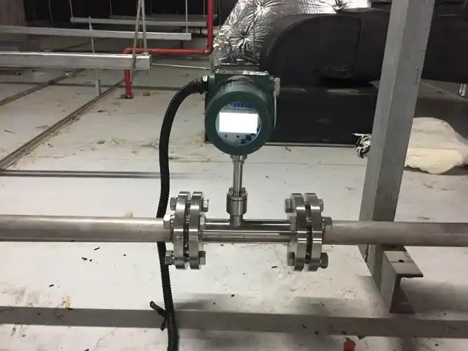
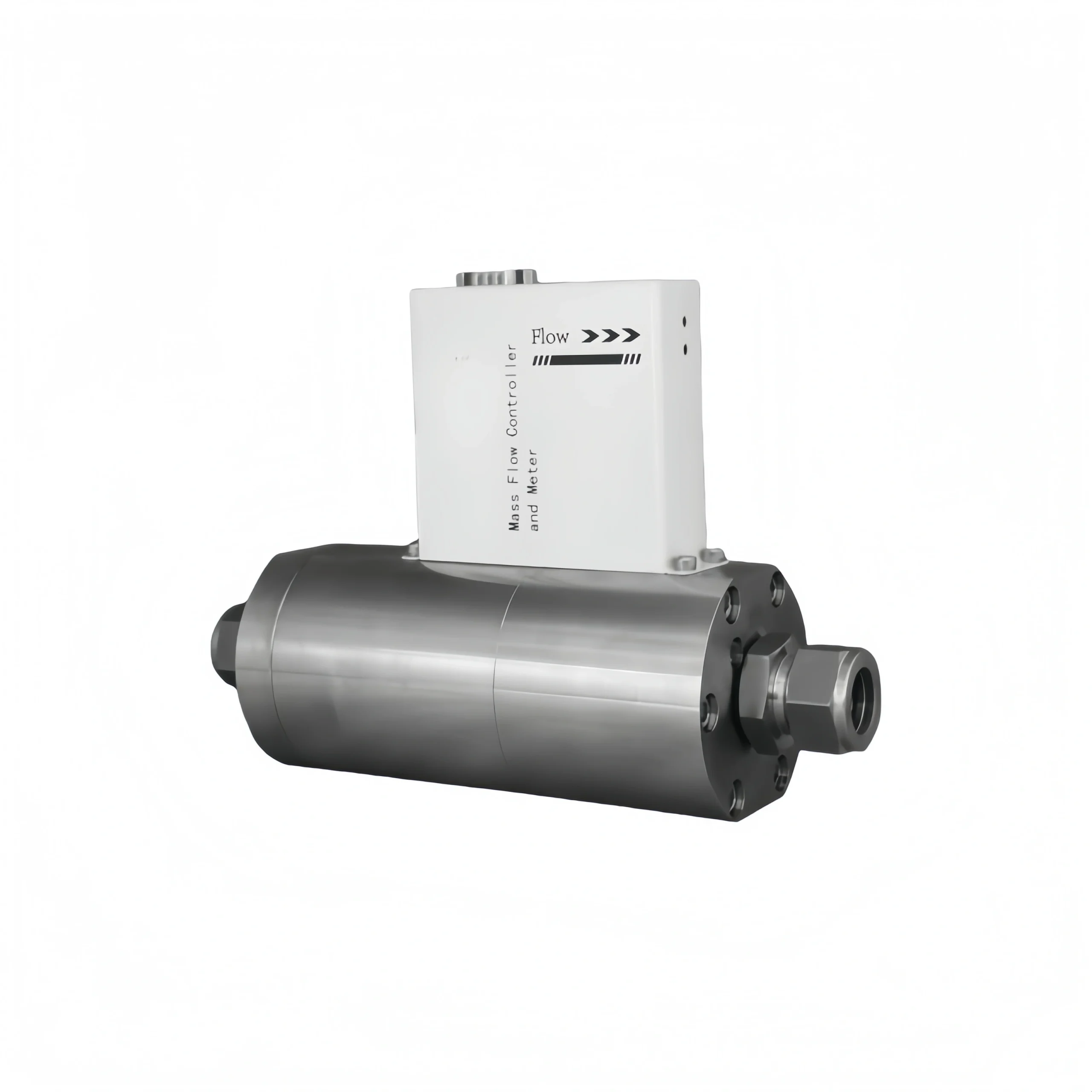
Thermal mass flow meters directly measure mass flow based on the principle of heat conduction in fluids; the equipment is fitted with a heating probe and a temperature-sensing probe.
When there is no fluid flow, the temperature difference between the two probes remains stable; when gas flows past the probes, it carries away heat from the heating probe, with a higher mass flow rate resulting in more heat being carried away per unit time.
The instrument operates in two modes:
constant-power mode, which measures flow by detecting changes in the temperature difference, and constant-temperature-difference mode, which adjusts the heating power to accurately calculate the flow rate.
This measurement method is unaffected by the temperature or pressure of the medium, requires no temperature or pressure compensation, and can directly output standard mass flow data.
Methods for Calibrating Thermal Mass Flow Meters
1. Comparison with a Standard Meter
Connect the thermal flowmeter to be calibrated in series with a standard flowmeter certified by an authoritative body (such as a sonic nozzle, Coriolis mass flowmeter or high-precision thermal flowmeter) in the same pipeline.
Under identical operating conditions, read the flow values from both instruments simultaneously and perform calibration by comparing the indicated value errors.
This method is simple to operate and suitable for on-site, online calibration; however, it requires that the accuracy of the standard flowmeter be at least one grade higher than that of the flowmeter under calibration.
2. Weighing Method (Static Mass Method)
At specific time intervals, the gas is passed through the flowmeter under calibration and collected in a container of known volume. The mass of the collected gas is measured using a high-precision balance, and the actual mass flow rate is calculated based on the measurement time, which is then compared with the flowmeter’s indicated value.
This is one of the benchmark methods for mass flow calibration; whilst it offers high accuracy, it is operationally complex and is typically carried out under laboratory conditions.
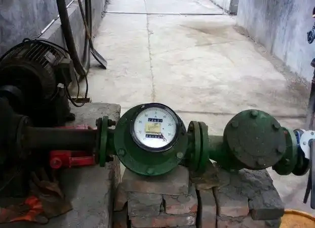
3. Volumetric Method (Static Volumetric Method / Dynamic Volumetric Method)
This method involves using a standard container (such as a standard volumetric tube or a gas-piston volumetric tube) or a precision-machined gas storage tank to measure the standard volume of gas flowing through it over a specific period of time.
This is then converted to mass flow rate by taking temperature and pressure into account. The dynamic volumetric method utilises a standard volumetric tube as the traceability standard and is suitable for the calibration of medium- to high-pressure gas flow rates.
4. On-site Online Calibration (Dry Calibration / Live-Flow Calibration)
Dry calibration: This does not involve the actual passage of fluid; it merely checks the flow meter’s electronic circuitry, sensor functionality and zero-point drift. It is usually carried out using calibration software provided by the manufacturer or a simulated resistance signal.
Live-flow calibration: A standard meter is connected to the actual working pipeline, or a portable standard device is used to perform an online comparison, ensuring accuracy under actual operating conditions.
Calibration Procedure
Pre-calibration Preparation
1. Equipment and operating conditions check:Fire up the equipment 1–3 hours ahead of time so it has a chance to warm up—this knocks out temperature drift in the sensors and circuitry; go over the pipework and make sure there’s no leaks, blockages, water buildup or dust, and double-check that the probe is clean with no oil or junk on it; confirm that the medium type, measurement range, and temperature and pressure parameters line up with the calibration standard.
2. Safety and Pipeline Isolation: Shut the valves upstream and downstream of the flowmeter; if you’ve got a bypass line, crack it open to fully isolate the flowmeter and keep process gas from messing with the calibration; bleed off any leftover pressure in the pipeline until it’s at atmospheric pressure and there’s no medium still moving through—this gets rid of calibration errors and safety risks from high pressure or gas flow fluctuations.
3. Connection of Calibration Equipment: Hook up the flow meter’s handheld programmer and communication debugging gear, and make sure the devices are actually talking to each other; get your standard calibration devices ready—stuff that’s already passed metrological verification (think sonic nozzles, bell-type gas calibrators, standard mass flow meters)—and check that the accuracy class of your standard equipment beats the flow meter under calibration by at least two levels, so you’re good on calibration accuracy.
4. Verification of environmental conditions:Make sure the temperature, humidity and atmospheric pressure in the calibration space stay steady, and that there’s no heavy electromagnetic interference, vibration or airflow disturbance. The environment has to meet metrological verification requirements, otherwise environmental factors will throw off your calibration data.
Zero-point calibration
1. Confirmation of zero-flow conditions:Make sure the upstream and downstream valves are fully shut, that nothing’s moving through the pipe, that the line is topped up with no venting or leaks anywhere, and watch the flowmeter’s live reading to catch any stray airflow or trickle flow that might be messing with your numbers.
2. Preheating and stabilisation of zero-point parameters: Keep things at zero flow for 10–30 minutes so the sensor’s temperature field can balance out completely. Monitor the flowmeter’s zero-point voltage and baseline readings until they flatten out and quit bouncing around—this wipes out zero drift from hot and cold spots.
3. Perform zero-point calibration: Get into the flowmeter’s calibration menu using a handheld programmer or the unit’s backend interface, punch in the device authorisation password, and pick the ‘Zero-point Calibration’ mode.The system will automatically collect zero-flow baseline data; once data collection is complete and the parameters have stabilised, manually confirm and save the zero-point calibration parameters. Do not interrupt the operation midway.
4. Verification of zero-point stability:Once calibration wraps up, keep an eye on the reading non-stop for 3–5 minutes. If the zero-point stays right around 0 without drifting or spiking, you’re good—calibration’s a success.If the zero-point keeps swinging around, run through the whole procedure another 2–3 times until it settles down and stays put, which should knock out any remaining zero-point offset completely.
Multi-point Range Calibration
1. Selection of Calibration Flow Points:Stick to the procedure and pick at least five flow points spread evenly across the range—usually 10%, 25%, 50%, 75% and 100%. If you want, throw in a couple extra points down in the lower end to make sure linearity holds up across the whole span and no local section drifts out of spec.
2. Steady-state flow testing at each point:Fire up the calibration gas source or standard flow device and dial it in to each preset flow point one by one. Hold the flow steady at each point for 3–5 minutes.Once both the flowmeter and the standard equipment have settled down and stopped drifting, jot down the actual mass flow rate from the standard and the reading off the meter you’re calibrating. Run each point 2–3 times and average the results to knock down random error.
3. Full-range data acquisition: Work through all the preset flow points in order, keeping the operating temperature and pressure locked in the whole way. Don’t go messing with the gas source parameters on a whim—you need every data set to be comparable. Record the raw measurement data for every point, no skipping.
Error Calculation and Parameter Correction
1. Measurement error calculation: Based on the standard values and measured values for each set of flow points, calculate the relative error and fundamental error for each point. Compare these against the flowmeter’s accuracy class requirements to determine whether the errors at each point fall within the permissible range.
2. Instrument parameter correction: If errors at certain flow points exceed the permissible limits, do not blindly adjust the zero point. Instead, use the flowmeter calibration system to fine-tune the instrument coefficient, range correction coefficient and segmented flow correction parameters.For low-range deviations, focus on correcting the baseline coefficient; for high-range deviations, focus on correcting the flow proportionality coefficient. Calibrate point by point until the errors comply with the equipment’s accuracy standards.
3. Repeat verification and calibration:After you’ve finished tweaking the parameters, go back and remeasure every calibration flow point to make sure the errors stay consistent across the whole range, that nothing’s busting through the tolerance limits, and that linearity and repeatability both stack up against the technical specs.
How to Maintain Thermal Mass Flow Meters
Routine Inspection and Maintenance:
Check the instrument daily and make sure it’s in decent shape—no damage, no water getting in, no dust buildup or condensation on the housing or junction box, and no gas leaking from pipe connections. Cross-check the flow and temperature readings on-site and remotely, and see if they’re holding steady without weird spikes or alarm codes popping up.
Make sure the instrument’s mounted solid, the pipework isn’t shaking itself apart, the terminal blocks aren’t loose or corroded, the supply voltage isn’t bouncing around, and the earth connection is doing its job properly.
Monthly Routine Maintenance:
Wipe the instrument casing with a clean, soft cloth to remove grease and dust; ensure dust and water protection is in place in harsh operating conditions. Tighten the wiring terminals, check that the shielding cable is earthed correctly, and ensure the wiring is undamaged.
Use low-pressure, clean compressed air to blow away surface dust from the sensor; at the same time, verify the instrument’s operating conditions and filtering parameters, and record data to investigate any zero-point drift issues.
Periodic Deep Cleaning:
After shutting down the system, depressurising and disconnecting the power supply, disassemble the sensor probe. Wipe away dust and light oil stains with anhydrous ethanol; soak stubborn stains in a specialised cleaning agent. Under no circumstances should hard objects be used to scrape the sensor elements.
After cleaning, allow the probe to air-dry thoroughly before reassembly. Check that the probe sheath’s corrosion protection is intact, replace the pre-filter cartridge, drain any accumulated liquid from the piping, and perform a static zero-point calibration.
Annual Calibration and Maintenance:
Conduct a full performance verification of the instrument annually; high-precision measuring instruments must be sent to a specialist organisation for calibration; recalibrate promptly if the composition of the medium changes.
Replace all aged seals, O-rings and other wear-prone components; verify compliance with straight pipe section requirements; investigate installation interference and potential pipeline hazards; and inspect and maintain insulation and vibration-damping facilities.
Maintenance during periods of inactivity:
If the equipment is to be taken out of service for an extended period, the probe must be thoroughly cleaned, dust protection must be ensured, and it must be isolated from corrosive media. During periods of inactivity, the power should be switched on periodically to prevent moisture build-up. Before putting the equipment back into service, the device and drain lines must be inspected, and the zero point recalibrated.
Safety precautions: Do not dismantle the probe whilst it is under pressure or live; do not alter the factory calibration parameters without authorisation; and ensure appropriate explosion-proof protection is in place when working with flammable or explosive media.
FAQ
What are the requirements for straight pipe sections?
Generally, the upstream straight pipe section must be ≥10 times the pipe diameter (10D), and the downstream section ≥5 times the pipe diameter (5D). If there are flow-disrupting components such as valves or elbows upstream, the straight pipe section must be appropriately extended.
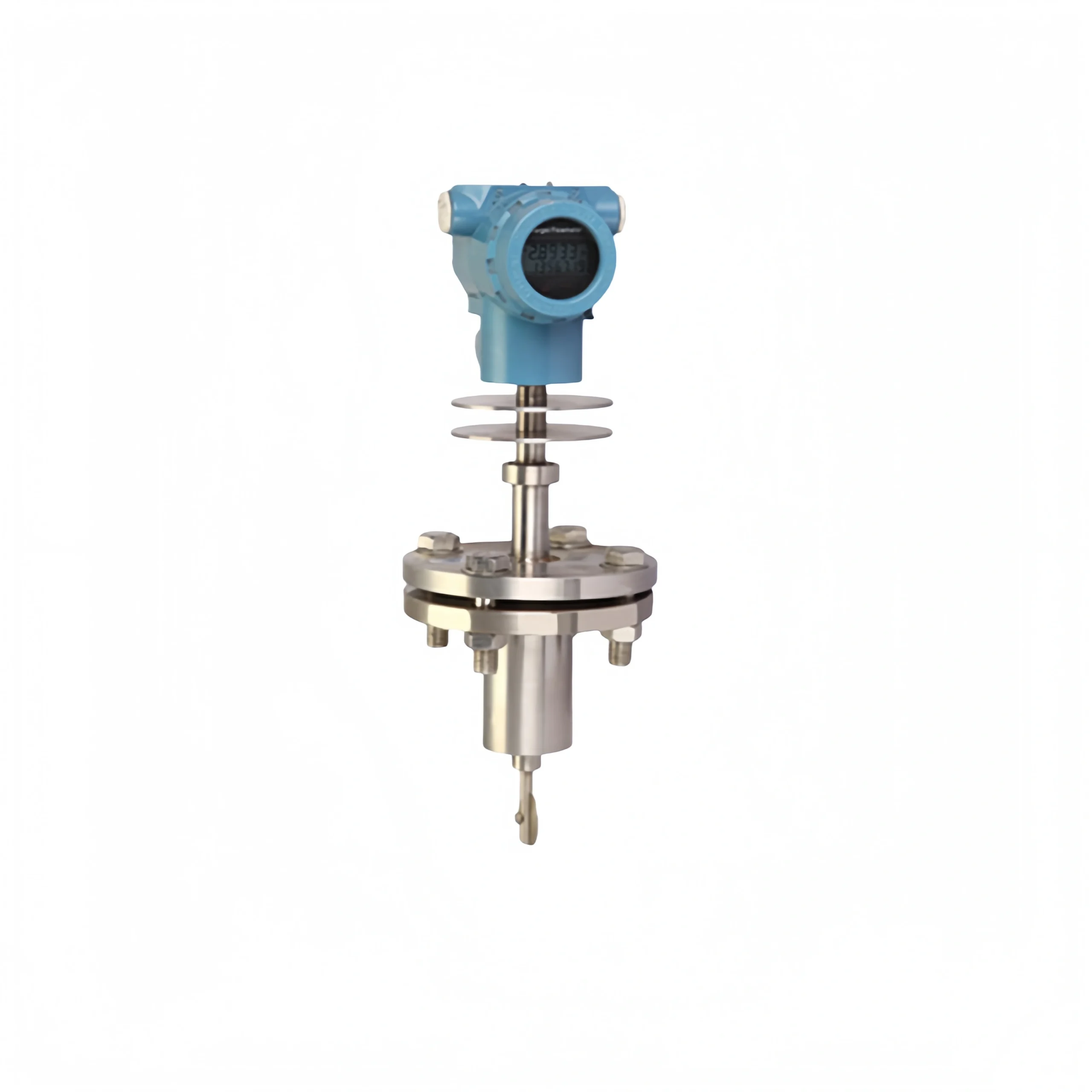
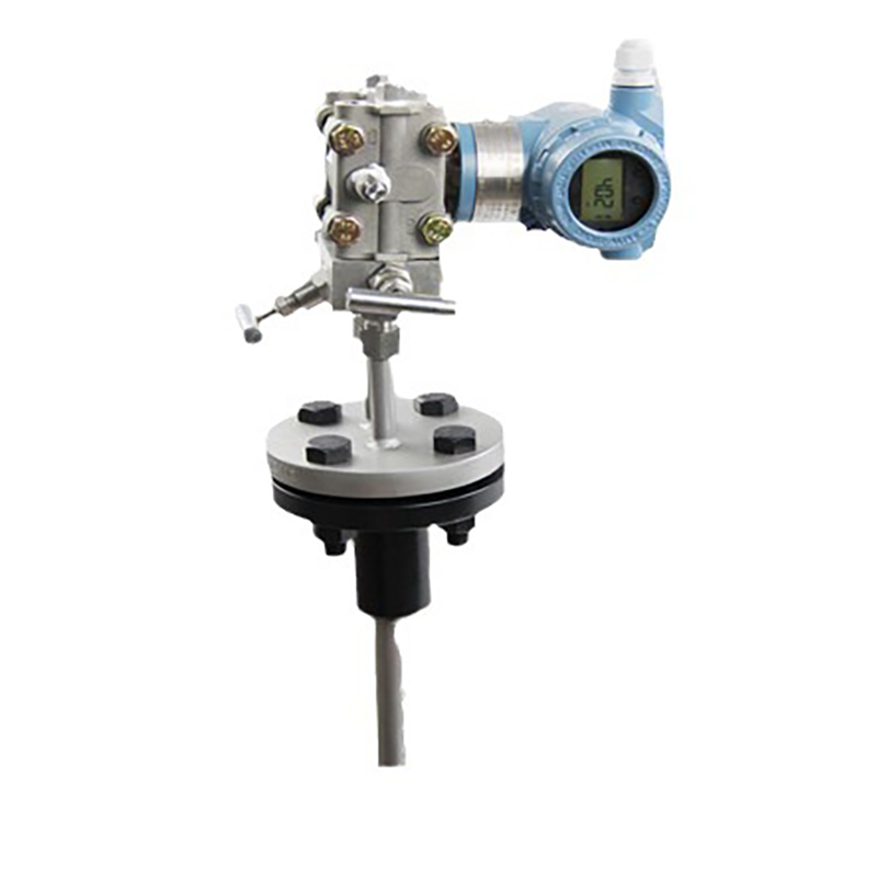
For insertion-type flowmeters, attention must also be paid to the insertion depth, which is typically at the centre point or the point of average flow velocity.
Must the calibration medium be the same as the service medium?
Ideally, the same medium or a substitute gas with similar thermal properties should be used. If air is used for calibration but natural gas is to be measured in practice, a correction must be applied using a conversion factor. Conversion factors may vary between manufacturers; please refer to the manual or consult the manufacturer.
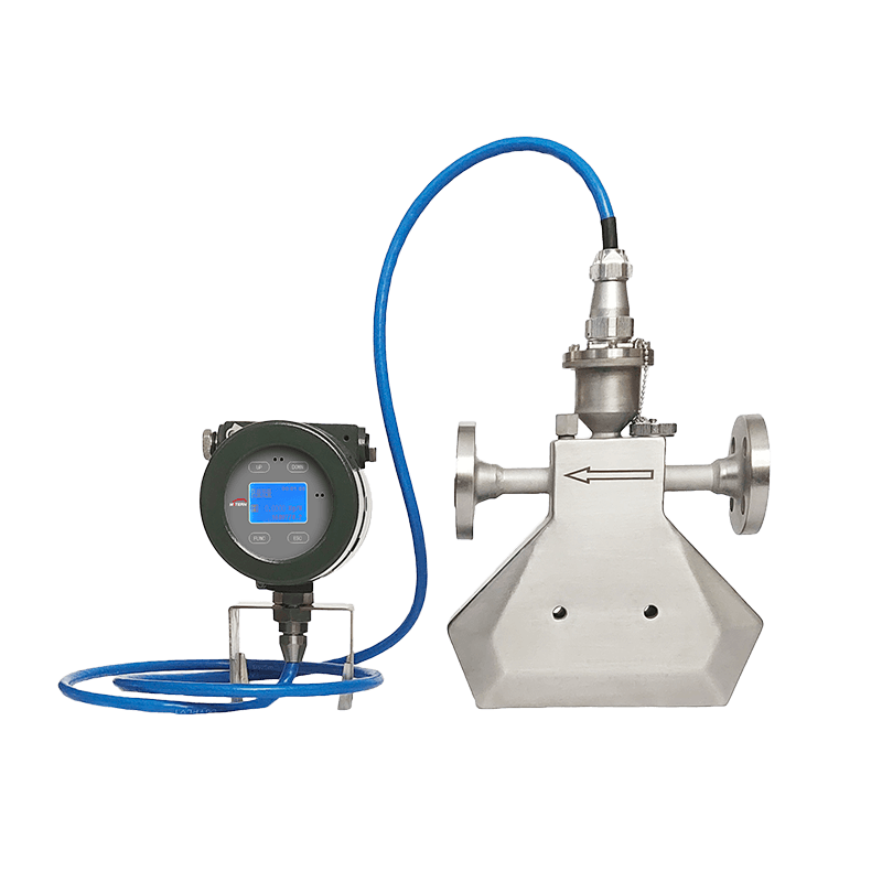
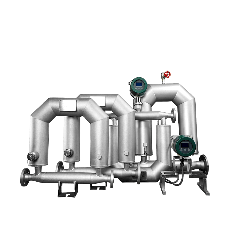
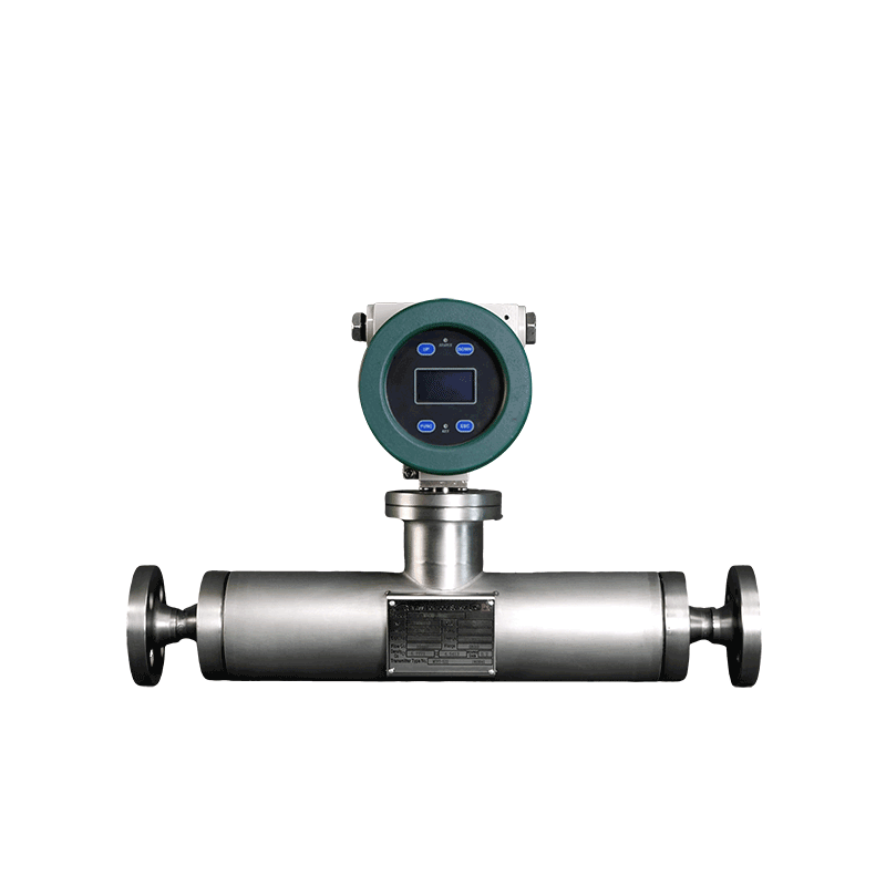
What is the difference between thermal flowmeters and Coriolis flowmeters?
Thermal flowmeters work well with clean, dry gases or liquids; they’ve got a wide turndown ratio (usually around 100:1), barely any pressure drop, and don’t cost a fortune. Coriolis flowmeters give you better accuracy (up to Class 0.1), can measure density and temperature at the same time, and handle multiphase flows and high-viscosity media; downside is they create more pressure drop and hit your wallet harder.
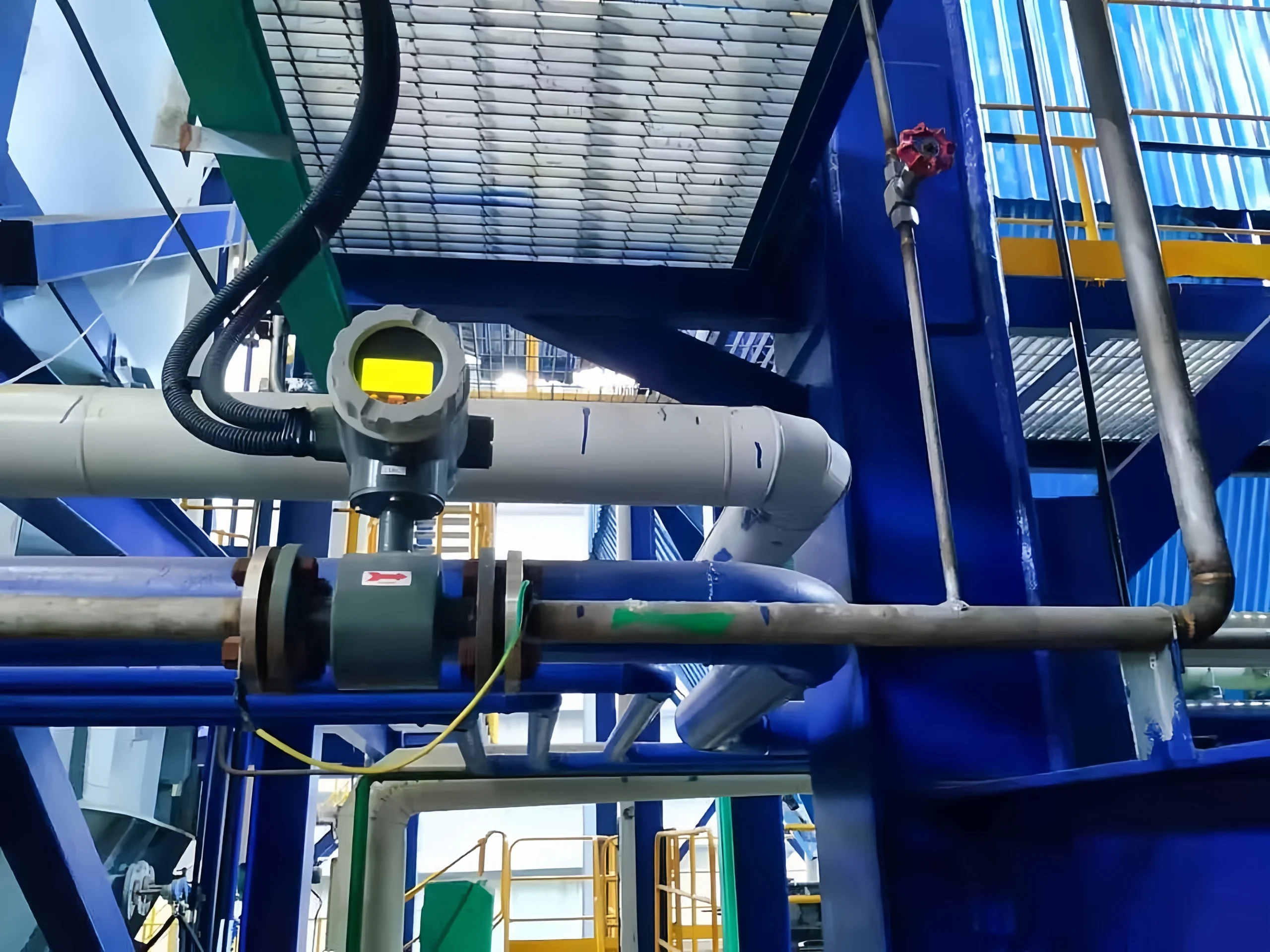
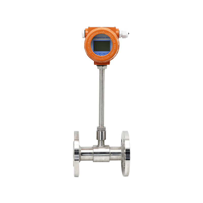
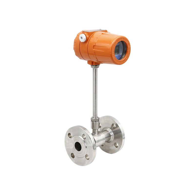
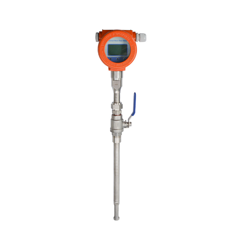
How do you pick between insertion-type and in-line flowmeters?
In-line flowmeters deliver higher accuracy and follow more standardised installation practices; they’re the go-to for small to medium pipe sizes (typically DN15 to DN200) and jobs where precision matters. Insertion-type flowmeters fit the bill for larger pipes (DN80 and up); they’re easier to put in and service, and they cost less. The trade-off is their accuracy doesn’t quite match in-line units, and you’ve got to be careful about insertion depth and positioning.
Precise flow measurement is fundamental to the stable operation of industrial production, energy consumption management and trade settlement, whilst standardised calibration and routine maintenance are essential for ensuring the long-term, high-precision operation of flowmeters.
Sion-Inst specialises in the research, development, sales and technical support of various industrial sensors and flow meters.
The company primarily deals in thermal mass flow meters, Coriolis flow meters, electromagnetic flow meters and other specialised measurement instruments for various operating conditions, with products covering the full spectrum of industrial applications, including chemical processing, gas, metallurgy, HVAC and precision manufacturing.