Pressure Transmitter Output Signal You Should Know

Table of Contents

Pressure transmitters monitor pressure and can be configured to output different signals. They typically generate both analog and digital signals. Output signals are sometimes categorized as current signals, voltage signals, and digital signals.

This article details the specific output signal types of pressure transmitters. We aim to provide you with a comprehensive understanding after reading.

What is a Pressure Transmitter?

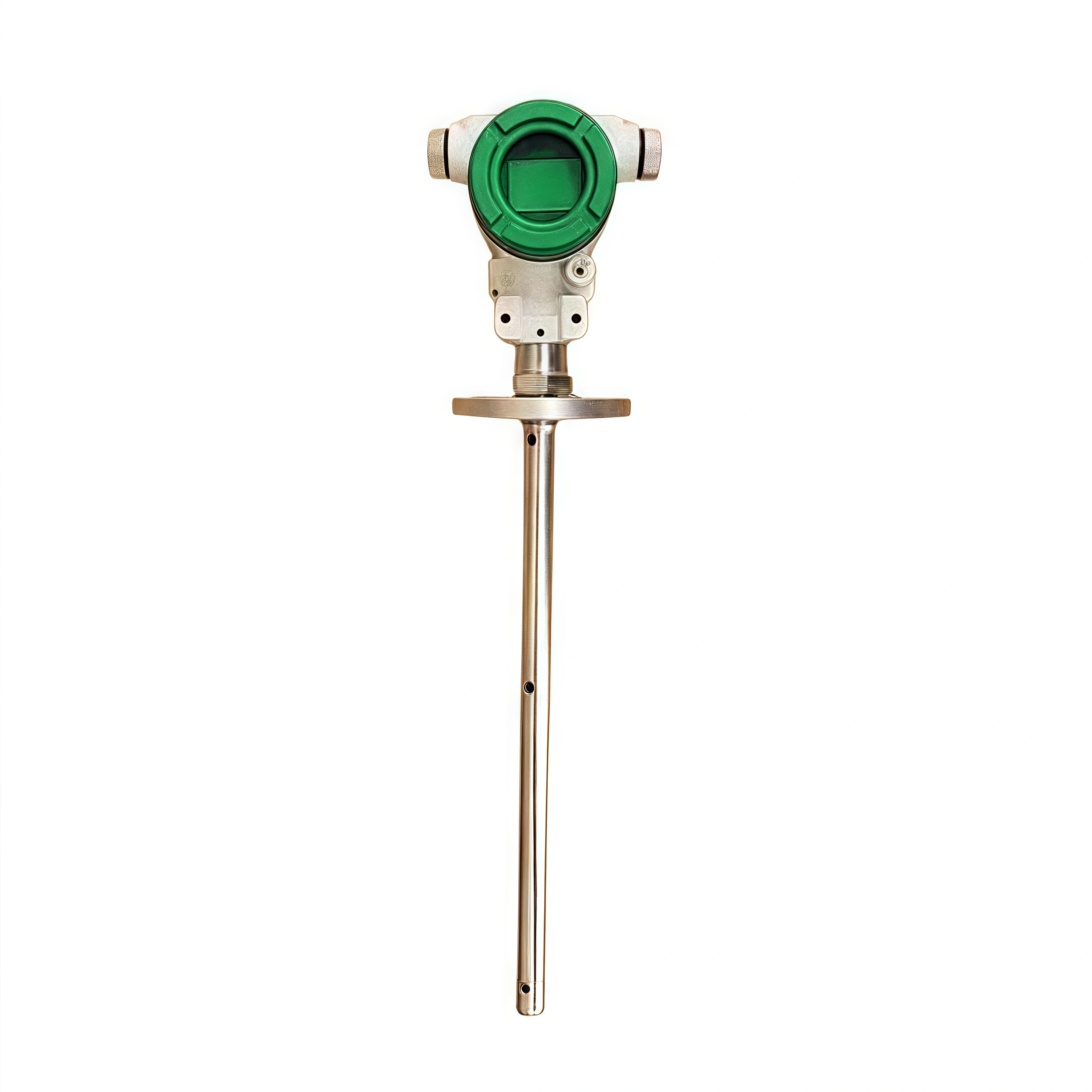
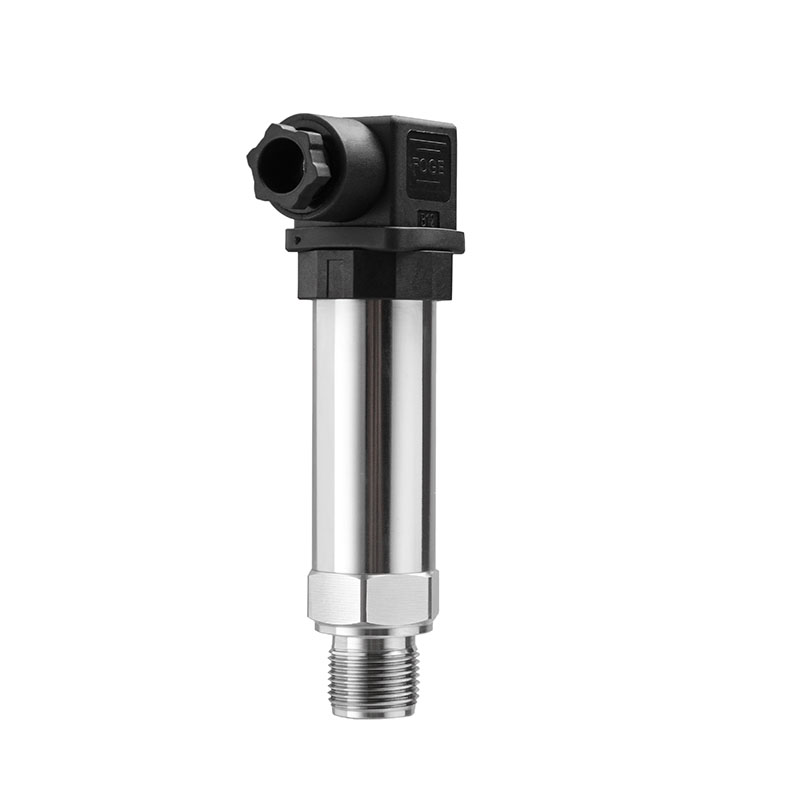
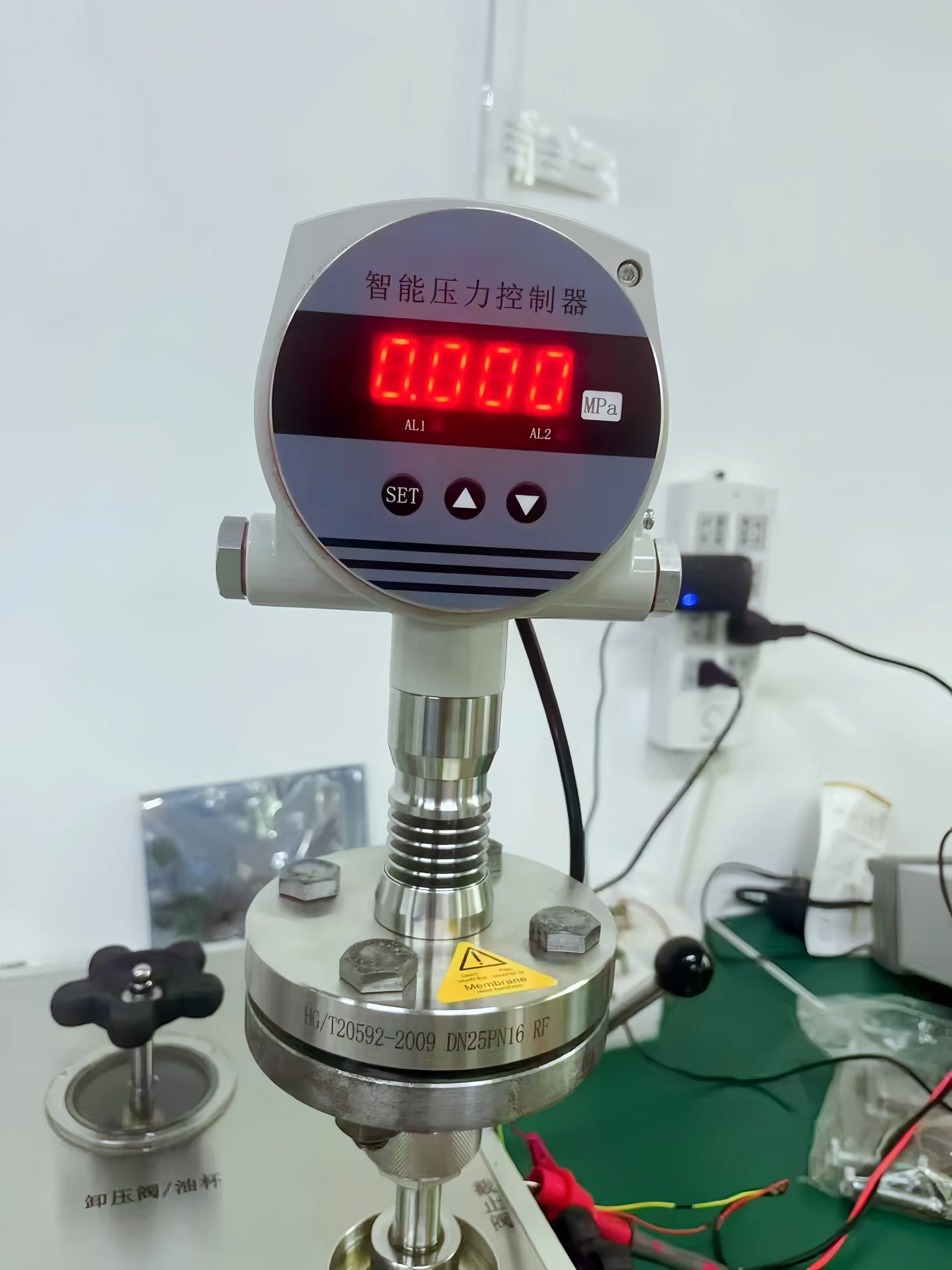
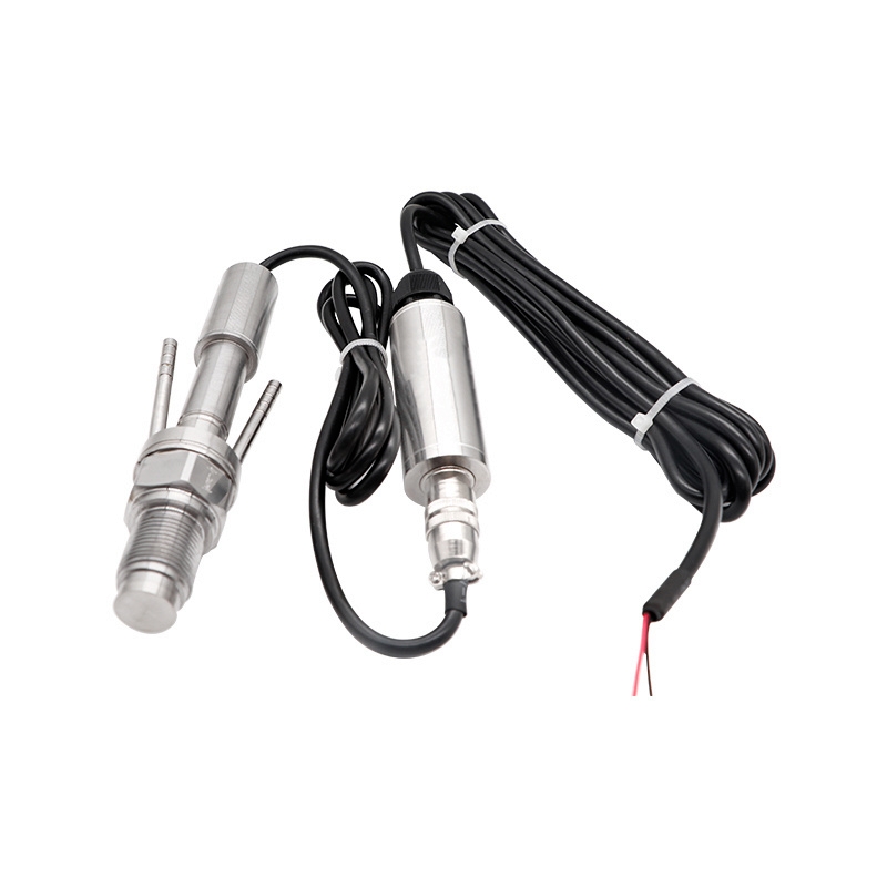
A pressure transmitter is a device that converts pressure into pneumatic or electrical signals for control and remote transmission. It transforms physical pressure parameters into standardized electrical signals. These electrical signals are supplied to secondary instruments(Alarm, Recorder, and Controller) for measurement and process regulation.

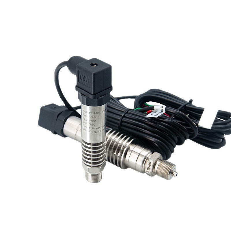
The primary function of a pressure transmitter is to transmit pressure signals to electronic signals. Its principle involves converting pressure signals into electrical current signals. Pressure maintains a linear relationship with voltage or current magnitude.

Read More about Types of Pressure Sensors: Different Types, Working Principles, and DefinitionsPressure Transmitter Progress

Pressure Transmitter Output Signal

The ultimate purpose of a pressure transmitter is to convert pressure parameters measured by sensing elements into standardized signals. Selecting the output signal type holds significant importance for the entire measurement system.

Conventional pressure transmitter output signals come in three forms: current output, voltage output, and digital output.

1. Voltage Output Signal (0–10 V, 5–10 V):
Pressure transmitters primarily employ voltage output.
However, voltage output transmitters encounter certain issues when signals require long-distance transmission. When operating in environments with severe power grid interference, it will affect the signal output.

2. Pressure Transmitter Current Output Signal (4–20mA):

Current output is the most commonly used signal output method for pressure transmitters. Current output signals are less susceptible to parasitic thermocouples, voltage drops due to wire resistance, and temperature drift. They experience minimal interference from external signals. Even with longer cable lengths, the transmission quality of the measurement signal remains unaffected.

3. Pressure Transmitter Digital Output Signals (RS-485, RS-232, MODBUS, HART)

The RS-485 output signal is digital. RS-485 offers strong interference resistance, facilitates integration with computer systems for processing, and enables convenient data storage.

MODBUS is a widely adopted serial communication protocol. When selecting digital signal output, compatibility with the control system’s communication interface and protocol must be considered. Compatibility ensures accurate and reliable data transmission.

HART protocol is a communication protocol that superimposes digital signals onto analog signals. Pressure transmitters using HART protocol output signals retain the traditional 4-20mA analog signal for real-time transmission of pressure measurements while transmitting richer information through the digital signal channel.

In modern signal processing technology, digital output signals play a significant role.

Current output and voltage output signals are collectively referred to as analog signals. RS-485 digital output signals are digital signals. Users must select the appropriate output type based on their specific operating conditions. It is essential to note that the wiring methods for each output signal type differ significantly. Users must carefully distinguish between them during installation and operation.

How to Read a Pressure Transmitter?

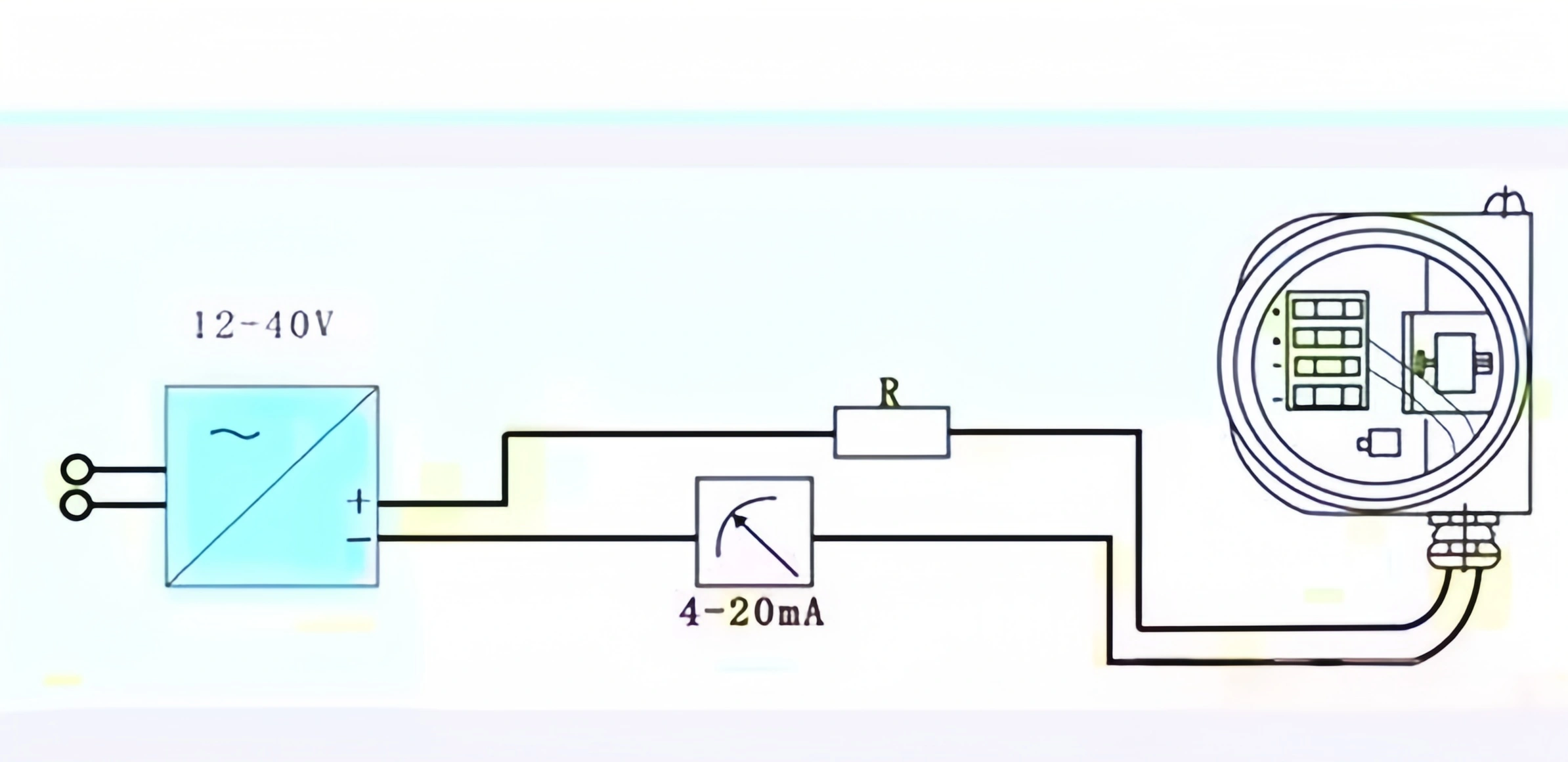
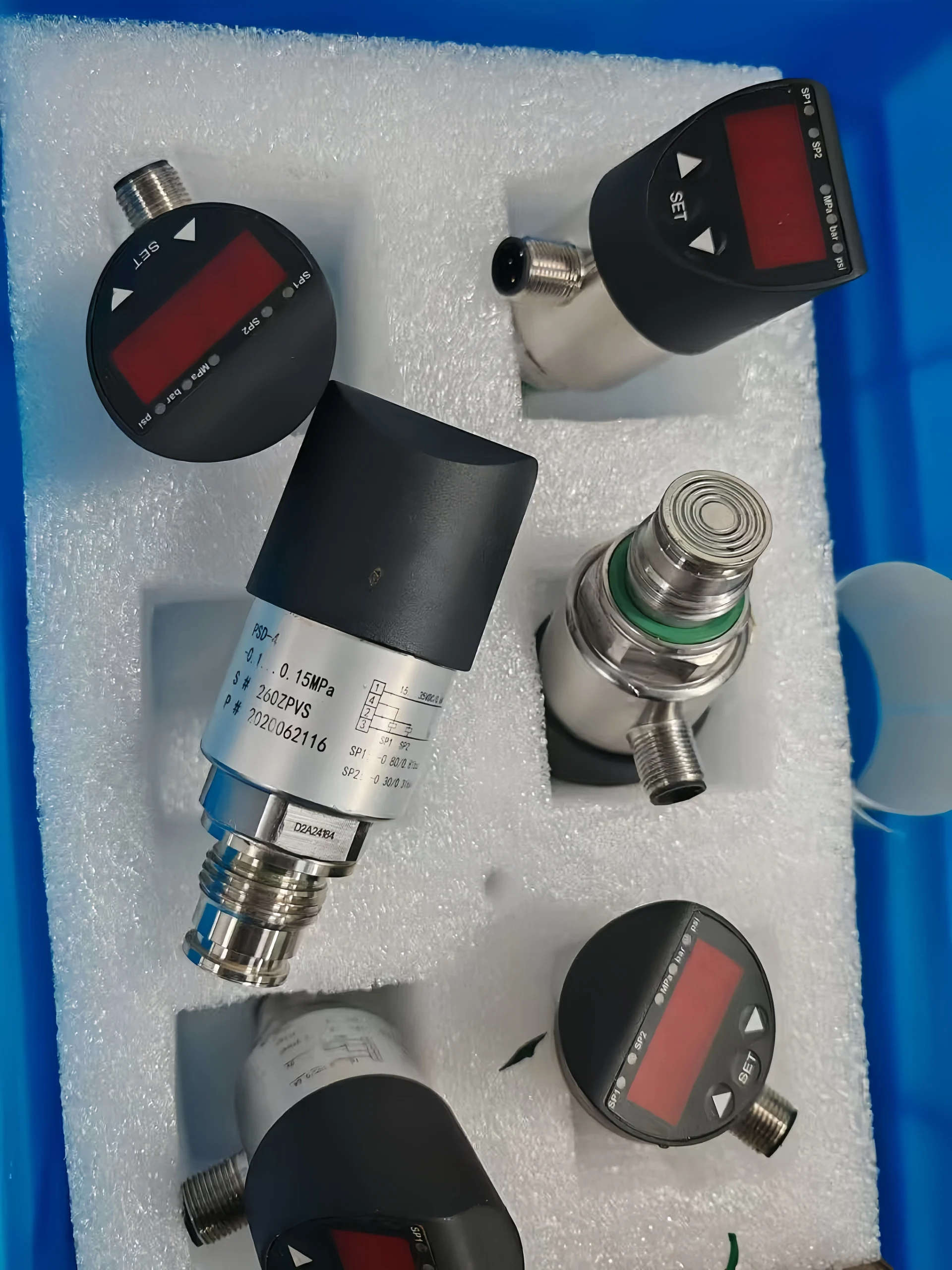
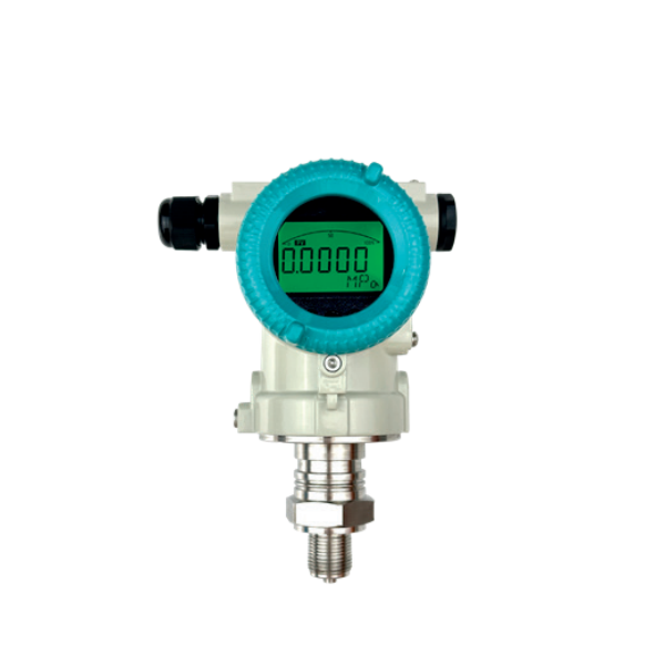
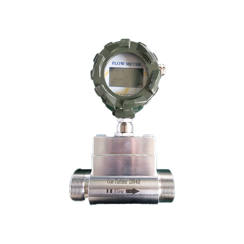
Generally, when a pressure transmitter has a display, we can directly read its signal. Without a display, we need to refer to the following methods to interpret the signal.

For pressure amplitude measurements using a current signal, a linear calibration equation is typically designed based on the transmitter’s range and sensor sensitivity. This equation converts the transmitter’s current output into a pressure value.

The calibration equation is: P = (I – I_min) * (P_max – P_min) / (I_max – I_min) + P_min
Where: P is pressure.
I is the current signal.

For example, if the transmitter’s measurement range is 0-1000kPa and the sensor sensitivity is 20mA/kPa, the calibration equation is:

I_max = 20mA, I_min = 4mA
P_max = 1000kPa, P_min = 0kPa

Thus, the calibration equation can be used to calculate the pressure corresponding to the transmitter’s output current. For example, if the transmitter outputs a 12mA current signal, the calculation is as follows:

P = (12mA – 4mA) * (1000kPa – 0kPa) / (20mA – 4mA) + 0kPa

P = 600kPa

From this, the pressure corresponding to the transmitter’s 12mA current signal is 600kPa.

Pressure Switch Output Display

Analog Signals and Digital Signals

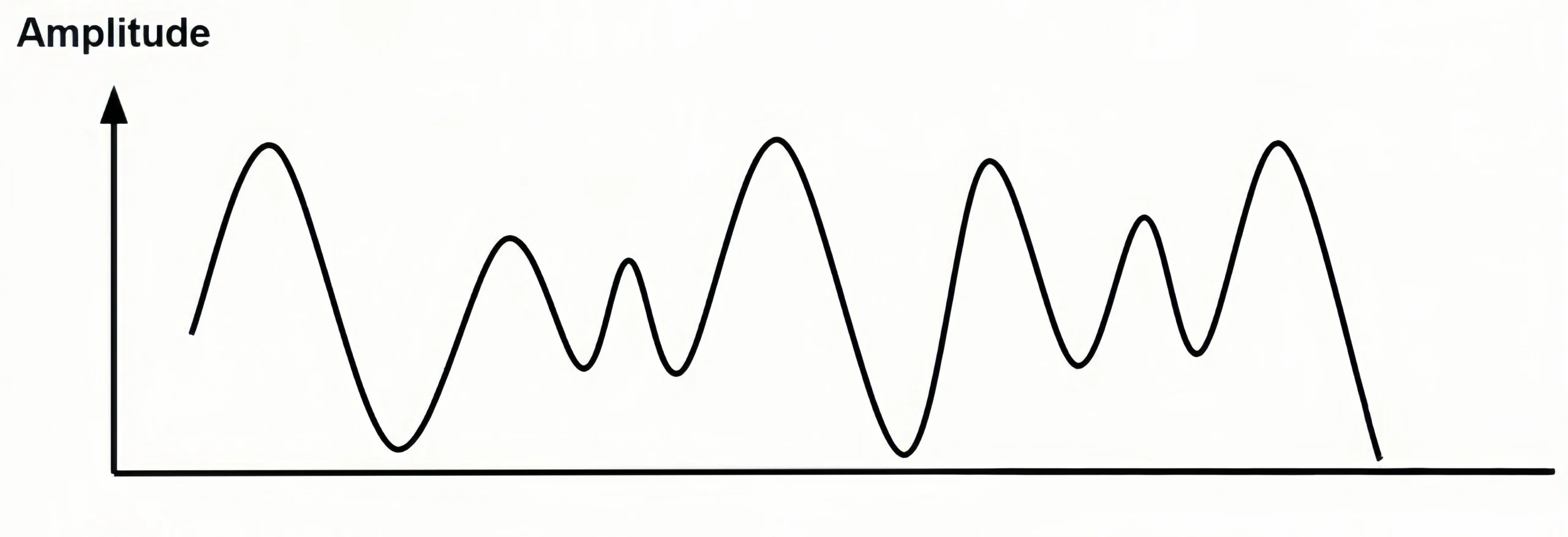
An analog signal is a continuously varying signal, while the amplitude and frequency of an analog signal vary with time. Analog signals are based on Continuous physical quantities such as voltage, current, temperature, and pressure.
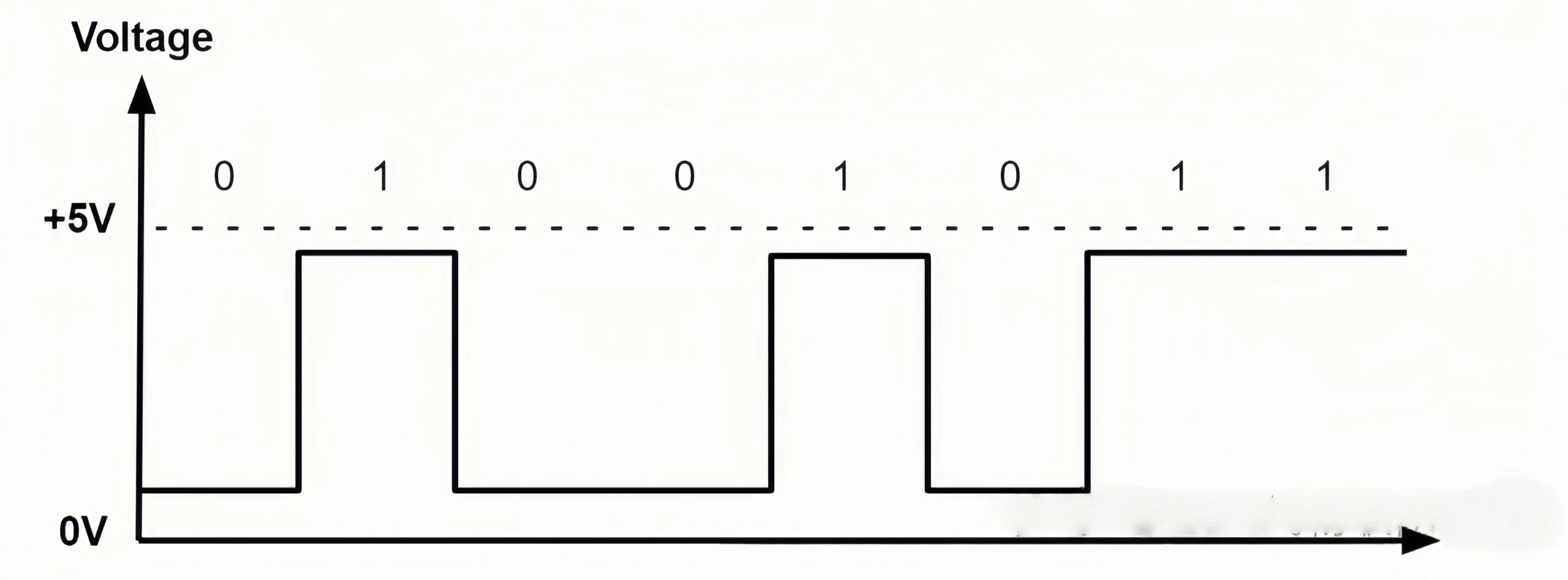
A digital signal is a discrete signal that can only take finite values. such as 0 or 1. Digital signals represent continuous analog signals by dividing them into many discrete points.

Digital and analog signals can be converted. In many modern control systems, converting the analog signals from pressure sensors into digital signals is crucial. Analog-to-digital converters (ADCs) serve as the core devices enabling this conversion, ensuring more precise and reliable control and monitoring.

However, signal conversion is not as essential for pressure transmitters. This is because you can communicate with suppliers to customize pressure transmitters that can output both types of signals simultaneously.

Digital signal
Digital signal
Analog signal
Analog signal

Comparison of Current and Voltage Signals

Definition differences between voltage and current signals:

A voltage signal refers to the potential difference in a circuit, describing the potential difference between two points. The commonly used unit for voltage signals is volts (V). In electronic circuits, voltage signals are usually expressed as direct current (DC) or alternating current (AC).

Electric current is generated by the flow of free electrons from a positive terminal to a negative terminal. Current signals are induced by magnetic fields. Charges move in an electric field to form a current. The strength of the current depends on the number and velocity of the charges. In a circuit, current is driven by voltage. Voltage provides energy to free electrons, giving them kinetic energy and enabling them to flow through the circuit. The unit of current is mA. The most common current output in pressure transmitters is 4-20 mA.

Specific differences between voltage and current signals

A voltage signal represents the potential difference between two points in a circuit. A current signal, on the other hand, represents the amount of charge flowing between the two points. In other words, voltage can be likened to “pressure” and current to “flow.”

Applications of Voltage Signals

Voltage signals are used in modern electronic devices and instrumentation, such as pressure transmitters, flow meters, and level gauges. In these applications, voltage signals are often used as control signals or input signals.

Sino-Inst Featured Pressure Transmitter

SI-2088 Customizable High Temperature Pressure Transmitter
Ultra-High Temperature Pressure Transmitter with Current voltage signal output
Ultra-High Temperature Pressure Transmitter
Model-CPT-20SD1-Cryogenic-Pressure-Transducer
Model CPT-20SD1 Cryogenic Pressure Transducer
Intelligent Pressure Sensor
Intelligent Pressure Sensor RS485
4-20mA Diaphragm Pressure Sensor G14 - M12-4 Pin Plug
Flameproof Pressure Transmitter Exd Explosion proof

How to Select the Suitable Output Signal for a Pressure Transmitter?

Based on Sino-Inst’s many years of customized experience, we have summarized the following parameters for selecting an output signal for your reference:

Measuring range:
Select the output signal according to the pressure range of the measured medium.
Typically, the 4-20mA signal is suitable for larger measurement ranges. The 0-10V signal is suitable for smaller measurement ranges.

Transmission Distance:
According to Ohm’s Law, when the transmitter’s output current flows through the loop, line resistance causes a voltage drop.
If the voltage drop is excessive, the receiving end’s voltage may fall below the minimum operating voltage requirement, leading to signal reception errors. Under normal wiring conditions, the transmission distance of 4-20mA is generally higher than that of RS-485.

Accuracy:
Select the output signal based on the measurement accuracy requirements of your working conditions.
Typically, the 4-20mA signal offers higher measurement accuracy.

Device Connection:
Select the output signal based on the device’s connection method and data processing compatibility.
For instance, digital signal output is typically chosen when connecting to PLC or DCS systems. And you can choose a suitable system according to your working requirements. We can also recommend the right measurement system to make your measurement process more flexible and smooth.

Cost and Budget:
Select the right output signal based on your budget and cost.
Digital signal outputs are generally more expensive than analog outputs.

So, thoroughly evaluating the above factors is crucial before deciding within your budget constraints. In short, if you’re still struggling to choose which signal output to use, contact us immediately. Let our professional engineers help resolve your issues.

Pressure Switch with Display

The electrical signal of a pressure transmitter refers to its electronic output relative to the mechanical input.

It encompasses both analog and digital signals, as detailed above.

The operating principle of a differential pressure transmitter is based on measuring the pressure difference between two distinct points in a fluid flow and converting this pressure differential into a standard electrical signal output. This output is typically a 4-20mA current signal or a 0-5V/0-10V voltage signal.

Read More about: differential pressure transmitter.

Use an oscilloscope to measure the pressure transmitter’s output signal.

An oscilloscope is another common tool for measuring electrical signals. Provide more precise waveform diagrams. To measure the pressure transmitter’s output signal, first connect the oscilloscope probes to the transmitter’s two terminals. Then, use the oscilloscope’s menu settings to adjust the horizontal and vertical scaling to observe the waveform of the output signal.

Using a Multimeter to Measure Pressure Transmitter Output Signals

A multimeter can be used to measure pressure transmitter output signals. Before measurement, connect the multimeter probes to the two terminals of the pressure transmitter. First, set the multimeter to voltage measurement mode. Then connect the pressure sensor’s output signal to the multimeter’s positive and negative terminals. The voltage displayed on the multimeter at this point represents the pressure sensor’s output signal.

Measuring the pressure transmitter output signal using a signal generator

A signal generator is an electronic device capable of producing analog signals. It can generate analog signals with various waveforms. When measuring the pressure transmitter output signal, a signal generator can be used to produce an input signal. This input signal is then connected to the pressure transmitter’s input terminal. The pressure transmitter’s output signal is subsequently connected to an oscilloscope or multimeter for measurement.

In summary, the signal output of a pressure transmitter is critical for its proper operation. Therefore, users are advised to select the output signal that best suits their specific requirements whenever possible.

If you have any questions regarding output signal selection, feel free to consult us anytime. We are your most reliable pressure sensor experts. Please reach out for a free quote at your convenience.

Welcome To Share This Page:
Product Categories
Latest News
Get A Free Quote Now !
Contact Form Demo (#3)

Related Products

Related News

A capacitive level sensor, also known as a capacitive level meter. It measures liquid level by converting changes in the

With the advancement of technology, sensors have become an integral part of equipment in industrial. And the level sensor has

There are many different technologies for level measurement. For example, differential pressure level meter. capacitive level meter. ultrasonic level meter,

Sensor technology is an indispensable part of modern industry, scientific research and daily life. Among them, air pressure sensors are

What is an Analog Flow Meter? An analog flow meter is a specialized device used to measure the flow of

There are a variety of factors to consider when measuring natural gas flow. These include gas properties, such as its

Compressed air is very common in industrial processes. Measuring the pressure of compressed air can ensure the safety of operators.

Flow switches and flow meters are commonly used in industrial measurement. Many people are not clear about their differences. A

Definition of 4-20mA pressure transmitter The 4- 20mA pressure transmitter can convert physical quantities into electrical signals. The most widely

Scroll to Top

Get A Free Quote Now !

Contact Form Demo (#3)