How to Install a Flow Switch and a Flow Sensor?

Table of Contents

There are many things to note when installing flow switches and flow sensors. Proper installation of flow switches and flow sensors can help control industrial processes. This blog will introduce how to install flow switches and flow sensors.propane flow meters

Definition of a Flow Switch and a Flow Sensor

Flow switch: A flow switch is mainly installed online or plug-in in water, gas, oil and other media pipelines. It monitor the flow size of the system. When the flow is higher or lower than a certain set point, the output alarm signal is triggered and transmitted to the unit. After the system obtains the signal, it can make corresponding indication actions. Thereby avoiding or reducing the “dry burning” of the host.

Flow sensor: Flow sensor, also often called flow meter. It is an instrument used to indicate the measured flow or the total amount of fluid in a specific time interval. The flow sensor can sense the fluid flow and convert it into a useful output signal. By placing it in the fluid path, the interaction between the fluid and the sensor is used to detect the change in flow.

How to Install a Flow Switch?

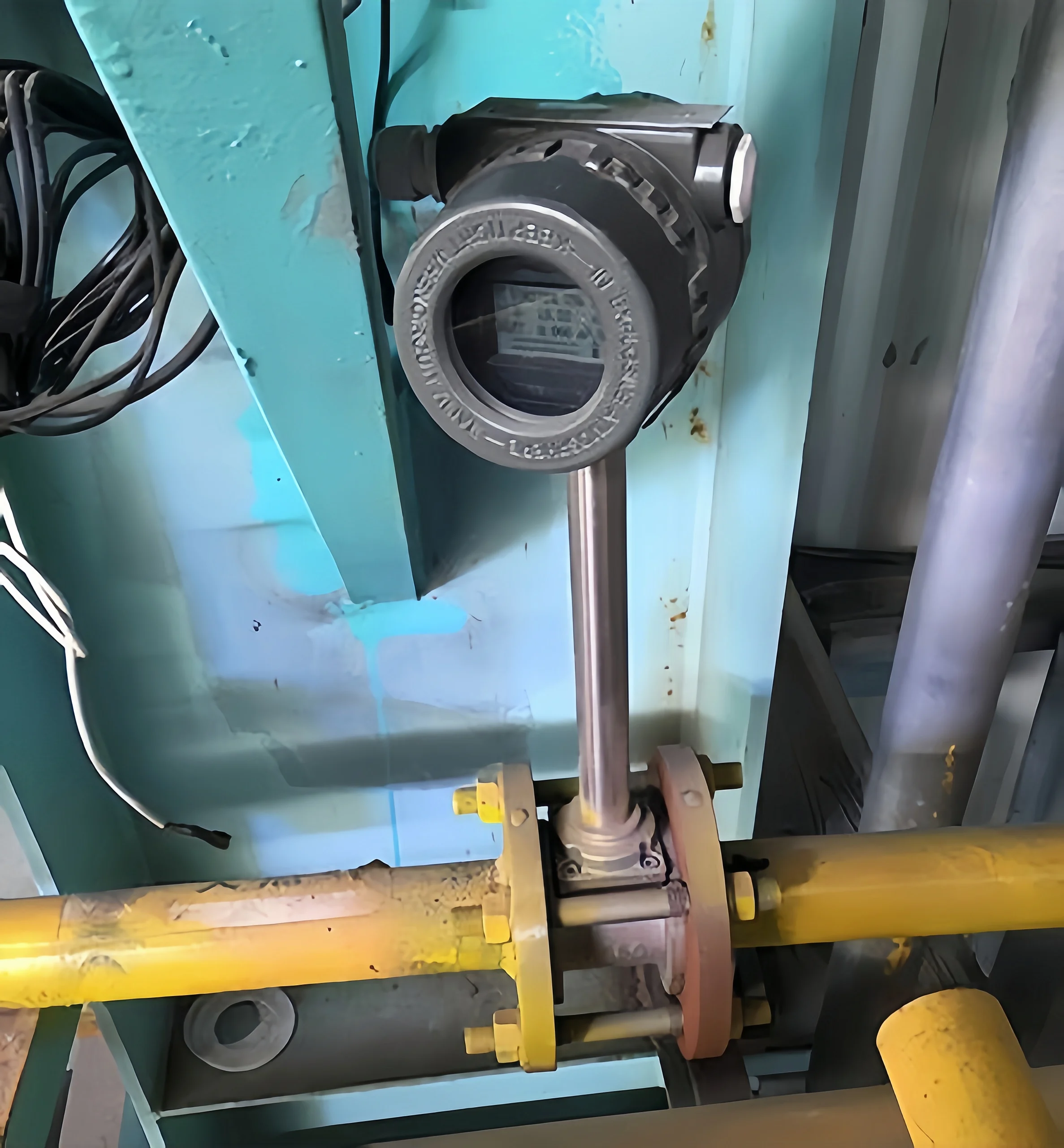
‌1. Installation location

Selection of stable flow pipe section

It is preferred to install it in a straight pipe section that flows horizontally or vertically upward. Avoid elbows, valves, reducing/expanding pipes and other areas prone to turbulence.

Straight pipe length requirements

upstream ≥ 10 times the pipe diameter; downstream ≥ 5 times the pipe diameter. (specific values need to be adjusted according to the type of flow switch).

‌Direction adaptability: ‌Mechanical flow switches must be installed according to the arrow mark and the direction of the fluid flow. Electronic flow switches must determine the direction according to the sensor structure such as thermal diffusion type must be perpendicular to the flow direction).

‌ 2. Environmental requirements: ‌ ‌

Vibration and shock avoidance

It is prohibited to install near high-frequency vibration sources such as pumps and compressors. Avoid failure of internal components due to resonance.

If it cannot be avoided, a shock-absorbing bracket or soft connection buffer device must be installed.

‌Temperature and pressure matching

The ambient temperature of the installation location should be lower than the rated temperature resistance of the equipment (conventional type: -20℃~80℃; high temperature type can reach 150℃);

Avoid installation in areas with severe pressure fluctuations (such as downstream of the pressure reducing valve) to prevent diaphragm or circuit overload.

3. Response plan for special working conditions‌

‌Multiphase flow medium treatment

In pipelines containing gas-liquid mixed fluids, vertical rising pipe sections should be selected for installation to avoid false triggering caused by bubble accumulation.

‌Corrosive and high-viscosity fluids

Corrosive media require anti-corrosion sleeves or fully sealed flow switches.

High-viscosity fluids (such as heavy oil) should shorten the maintenance cycle to avoid clogging of the sensing part.

4. Maintenance and calibration of space reservation‌

‌Operation accessibility

The installation location needs to reserve ≥50cm of lateral operation space for manual reset or parameter calibration;

Electronic equipment needs to ensure that the junction box is oriented in a convenient maintenance position.

‌Signal test interface configuration

It is recommended to add a pressure gauge interface or sampling valve downstream of the flow switch to compare the consistency of the measured flow and signal output.

5. Verification process after installation‌

‌No-load test‌:

Pass fluid with 10%~15% of the rated flow rate to verify the low flow alarm function;

‌Full load test‌:

Gradually increase to the maximum flow rate and check the stability of the switch contact action;

‌Signal output calibration‌:

Verify the signal linearity through a standard ammeter (4~20mA) or a frequency meter, and the error must be <±2%FS.

Flow Switch

Precautions for installing a flow switch

  1. After installation, the flow switch needs to be calibrated.
  2. Operate according to the instructions of the flow switch.
  3. Ensure that it works normally within the set flow range.
  4. Keep the pipeline clean and not blocked.
  5. After installation, the flow switch needs to be maintained regularly.

How do You Install a Flow Sensor?

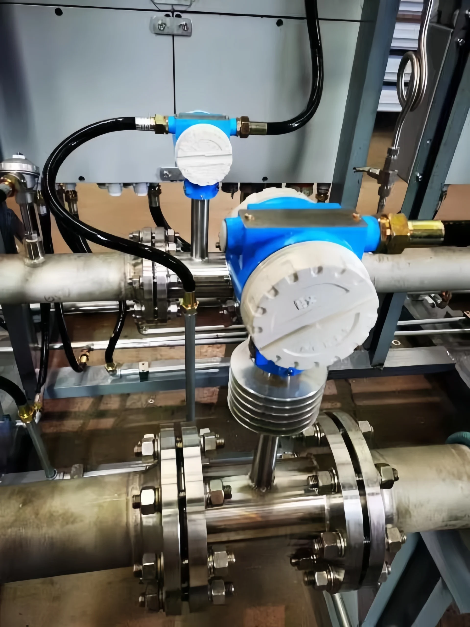
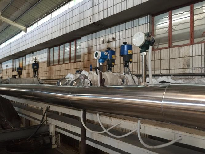
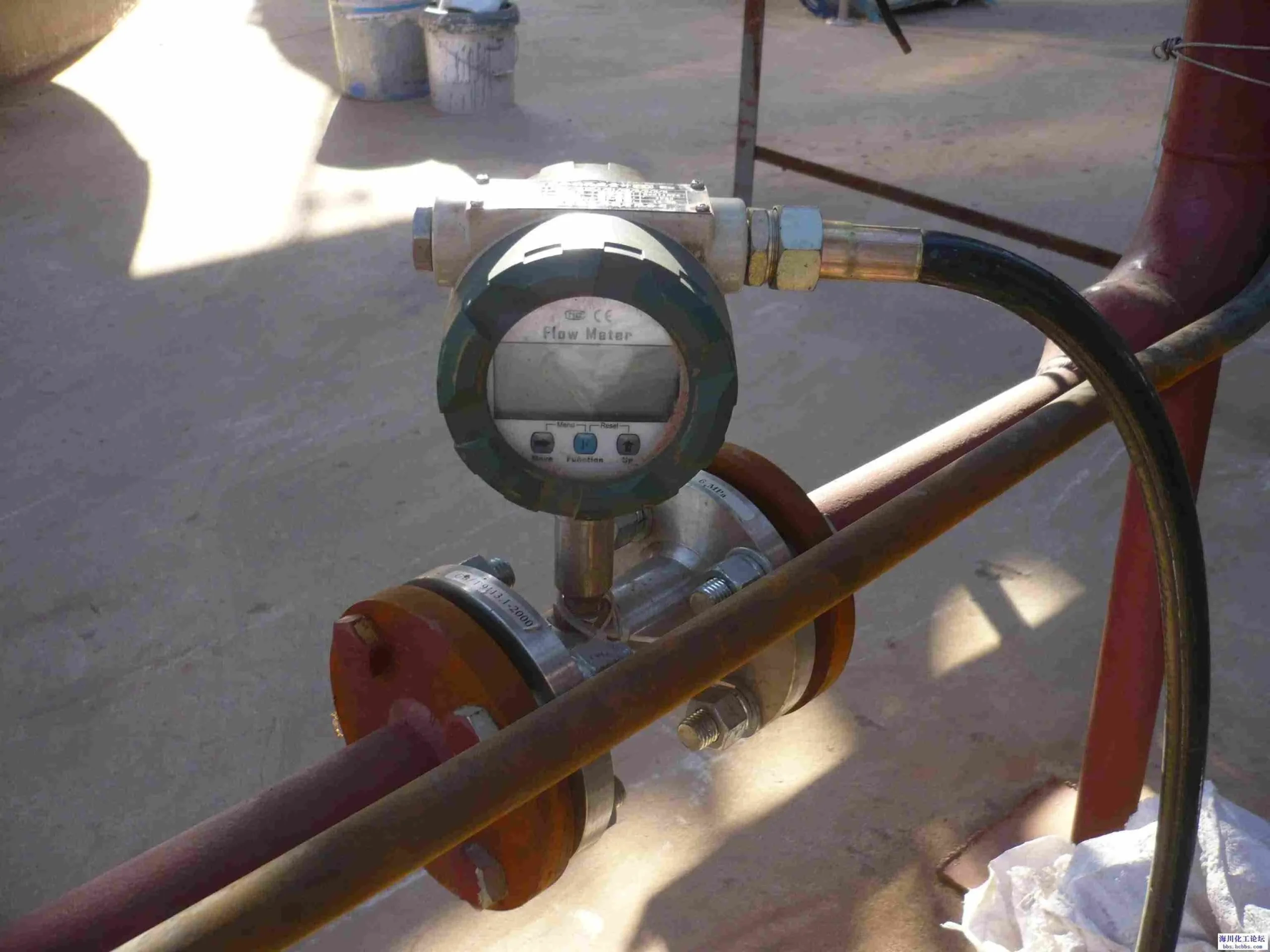
Flow sensors are also called flow meters. Common flow meters include electromagnetic flow meters, vortex flow meters, turbine flow meters, ultrasonic flow meters, Coriolis mass flow meters, thermal mass flow meters, differential pressure flow meters and volumetric flow meters. Next, I will introduce the installation method of the electromagnetic flow meter.

Electromagnetic flow meter:

1 Requirements for an external environment

  1. The flowmeter should not be installed in places with large temperature changes or high temperature radiation from the equipment. If it must be installed, insulation and ventilation measures must be taken.
  2. The flowmeter is best installed indoors. If it must be installed outdoors, it should be avoided from rain, water accumulation and sun exposure. Moisture-proof and sun-proof measures must be taken.
  3. The flowmeter should not be installed in an environment containing corrosive gases. If it must be installed, ventilation measures must be taken.
  4. To facilitate installation and maintenance, there must be sufficient installation space around the flowmeter.
  5. The flow meter installation site should avoid strong magnetic fields and strong vibration sources. If the pipeline vibrates greatly, there should be supports on both sides of the flow meter to fix the pipeline.

2 Requirements for straight pipe sections

In order to improve the influence of eddy currents and flow field distortion, there are certain requirements for the length of the straight pipe sections. Otherwise, the measurement accuracy will be affected. (Rectifiers can also be installed, and installation near regulating valves and half-open valves should be avoided as much as possible).

3 Requirements for process pipes

The flow sensor has certain requirements for the upstream and downstream process pipes of the installation point, otherwise the measurement accuracy will be affected.

  1. The inner diameter of the upstream and downstream process pipes is the same as the inner diameter of the sensor. It should meet the following conditions: 0.98DN≤D≤1.05DN (where DN: sensor inner diameter, D: process pipe inner diameter)
  2. The process pipe and the sensor must be concentric. The coaxial deviation should not exceed 0.05 DN.

4 Requirements for bypass pipes

In order to facilitate the maintenance of the flow meter, it is best to install a bypass pipe for the flow. In addition, a bypass pipe must be installed for heavily polluted fluids and flow meters that need to be cleaned. But the fluid cannot be stopped.

target flow meter

Precautions for installing electromagnetic flow sensors

1. The installation dimensions must be calculated accurately, otherwise, it is easy to leak or fail to install.

2. The fluid flow direction must be consistent with the flow direction arrow on the sensor body.

3. The electrode axis of the flow sensor must be approximately horizontal. Otherwise it will affect the measurement accuracy.

4. The flanges on both sides of the sensor must be kept parallel, otherwise, it is easy to leak.

5. In order to avoid the formation of vortex flow after installation, it should be ensured that the process piping and the coaxial connection of the flowmeter cannot be staggered.

6. When installing the flowmeter, it is strictly forbidden to weld close to the flange to avoid burning the flowmeter lining.

7. For process pipelines of different properties, the corresponding grounding method should be adopted.

8. For corrosive media, it is best to install it vertically, and the measured medium flows from bottom to top. This can avoid the deposition of solid particles in the flowmeter tube, make the lining corrode evenly, and extend the service life.

9. For measuring tubes with a diameter greater than 200mm, a telescopic head can be used for easy installation.

What are the Two Types of Flow Switches?
  1. Electronic flow switch

An electronic flow switch is a flow switch that uses electronic technology to achieve flow control. It uses microelectronics technology and digital signal processing technology to measure flow. The opening and closing of the solenoid valve is controlled according to the preset flow value, thereby realizing rapid control of the flow.

Advantages: high precision, rapid response, good anti-interference ability.

Disadvantages: expensive, service life is short. Due to the limitations of life and the stability of electronic components.

  1. Mechanical flow switches

A mechanical flow switch is a flow switch that realizes flow control based on a mechanical structure. It usually adopts structures such as vane flow meters or float flow meters. The output signal is driven to control the opening and closing of the solenoid valve by the fluid flowing through the vanes or floats in the flow meter.

Advantages: cheap price and relatively long service life. Suitable for some occasions where flow accuracy and response speed are not high.

Disadvantages: Due to the limitations of the mechanical structure itself, it cannot meet certain special requirements, and there are also certain problems such as power consumption and noise.

How do I choose a Flow Switch?
  1. Flow range: According to the actual application scenario, determine the flow range and select a flow switch.
  2. Switch type: Choose the appropriate flow switch type according to the fluid type, such as turbine type, vortex type, ultrasonic type, etc.
  3. Pressure and temperature: Consider whether the flow switch can withstand the pressure and temperature changes in the actual working environment.
  4. Accuracy and reliability: Choose a flow switch with higher accuracy and better stability according to actual needs.

Installing flow meters and flow switches is complicated. If you read this article and still don’t know how to install flow switches and flow sensors. You can contact us. You can email us or call us directly.

Sino-Inst has many measurement products. We have been deeply involved in the instrument measurement industry for more than 20 years. We have professional engineers. Professional engineers can guide you on how to install flow switches and flow sensors. You can also consult us for other related issues about instrument measurement. Please feel free to contact us.

Welcome To Share This Page:
Product Categories
Latest News
Get A Free Quote Now !
Contact Form Demo (#3)

Related Products

Related News

Flow switches and flow meters are commonly used in industrial measurement. Many people are not clear about their differences. A

A flow switch is an instrument used to control the flow of a medium (gas, liquid, oil) flowing through a

Sino-Inst is a professional supplier of flow switches. Based on experience, this article will introduce: What is a flow switch?

How Do You Measure Oil Flow? How to measure the flow rate of PetroChina and other high viscosity liquids in

What is an Ultrasonic Clamp-On Flow Meter? Ultrasonic flow meter is a non-invasive flow sensor used to measure the volume

Definition of 4-20mA pressure transmitter The 4- 20mA pressure transmitter can convert physical quantities into electrical signals. The most widely

7 Types of Pressure Sensors: Different Types, Working Principles, and Definitions What is a pressure sensor? A pressure sensor is

What is hydrostatic pressure? Hydrostatic pressure is the pressure exerted by a stationary fluid due to the effect of gravity.

What Is an Oil and Gas Pressure Sensor? Oil and gas pressure sensors are devices used by the oil and

Scroll to Top

Get A Free Quote Now !

Contact Form Demo (#3)