Differential pressure transmitters are the go-to for measuring pressure in industrial processes. You’ll find them used in all sorts of industries, like petrochemicals, power generation and metallurgy. The quality of their installation affects how accurate the measurements are, how stable the equipment is and how safe the production systems are. If you install it properly, you can be sure the equipment will work as it should, last longer and avoid any problems caused by poor installation.
What is a Differential Pressure Transmitter?
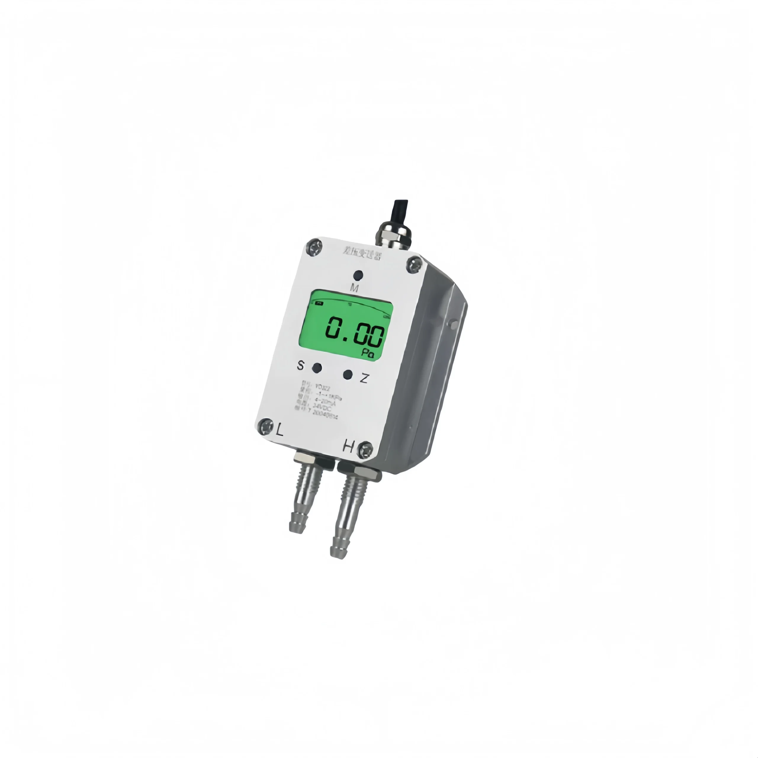
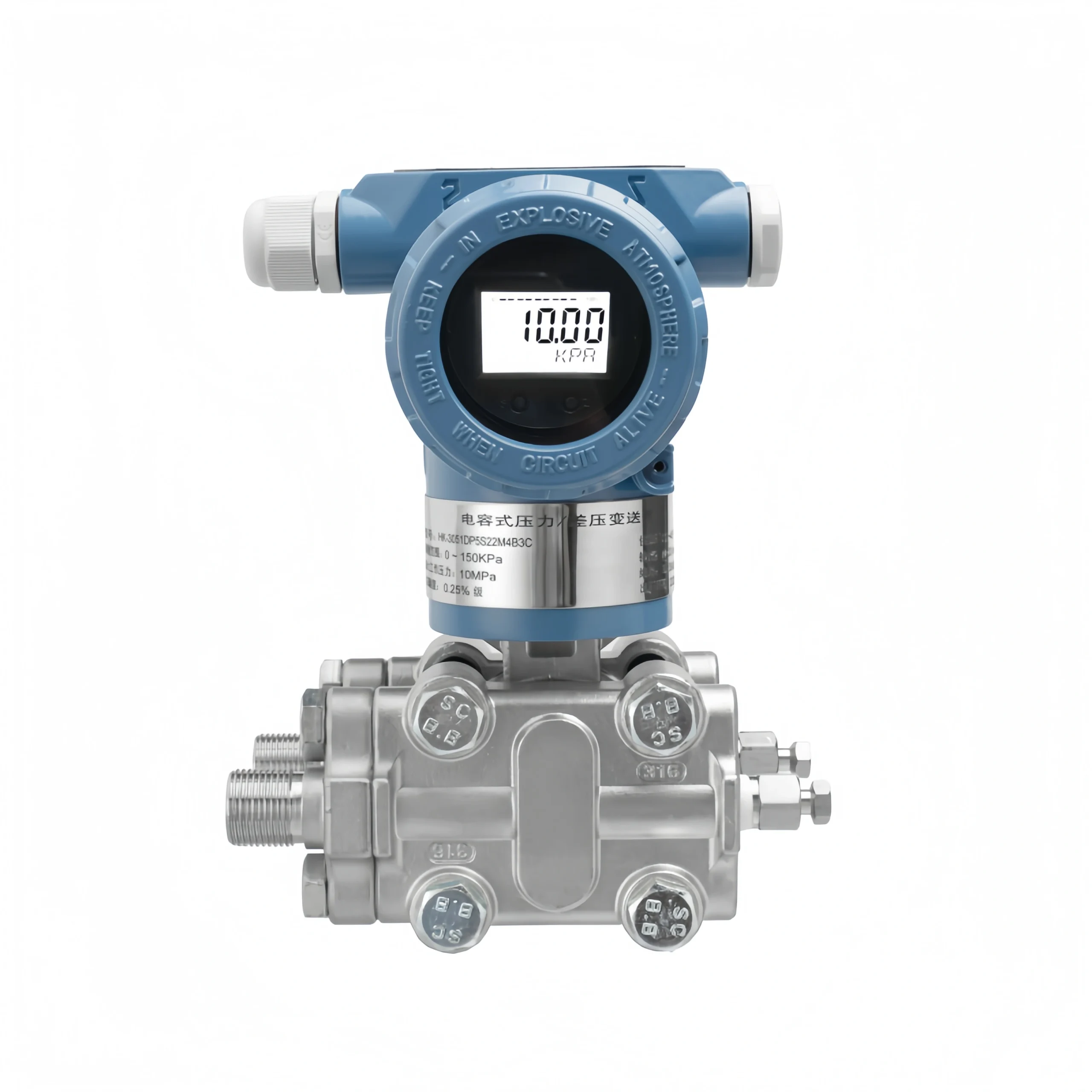
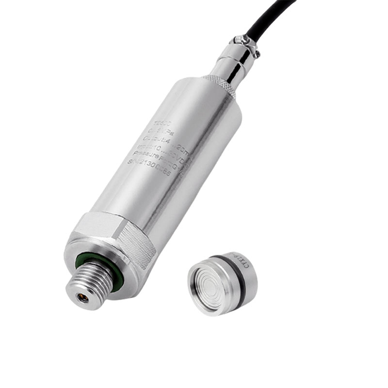
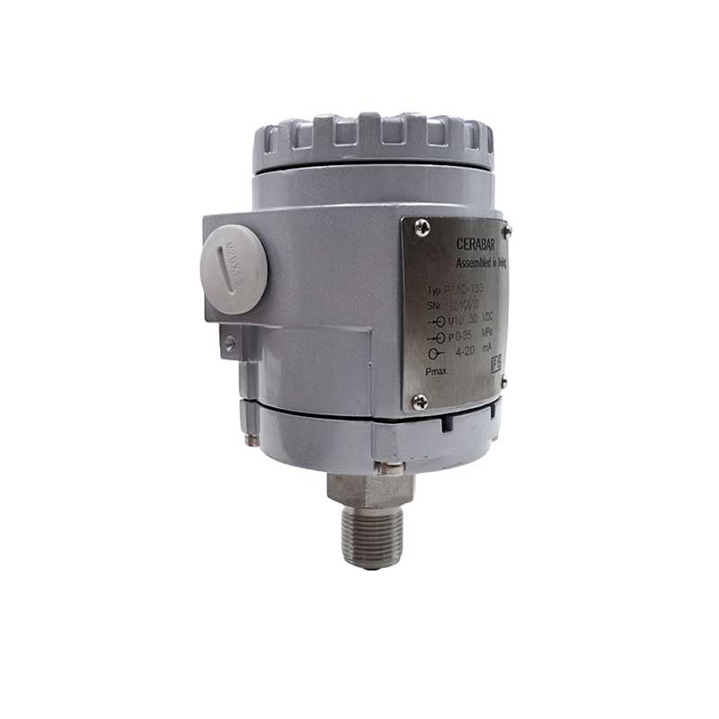
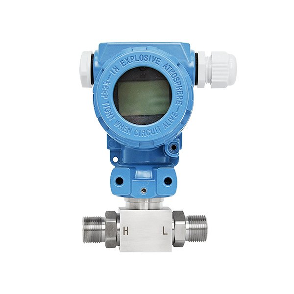
A differential pressure transmitter is an industrial instrument that measures the pressure difference between two points. It is used to monitor levels, flows, densities and differential pressures. It changes the pressure signal into a normal electrical or digital signal. This is then used by control systems to check and control things.
Working Principle of Differential Pressure Transmitters
The core operation relies on pressure-sensing elements, which are typically piezoresistive, capacitive, or strain-gauge sensors. When pressure is applied to both sides of an element, it either deforms or its electrical parameters change.
The pressure differential introduced on the high and low-pressure sides causes the sensitive element to generate a weak electrical signal, which is processed by conditioning circuits including internal amplification, temperature compensation and linearisation.
The processed signal is converted into a stable 4–20 mA analogue or digital signal (such as HART or RS485) for output, enabling precise measurement and remote transmission of the differential pressure.
When measuring liquid level, the height is calculated using the static pressure difference of the liquid; when measuring flow rate, the flow is calculated in conjunction with a flow restrictor based on the relationship between differential pressure and flow velocity, ultimately enabling the monitoring of various process parameters.
Installation Methods for Differential Pressure Transmitters
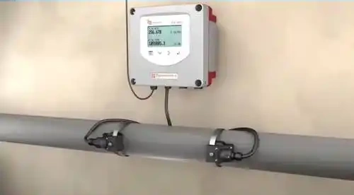
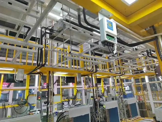
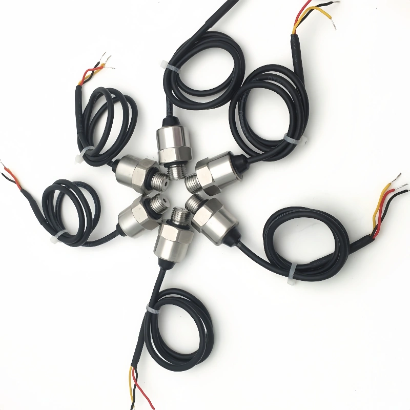
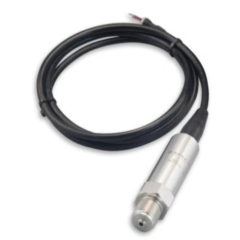
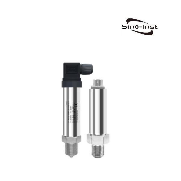
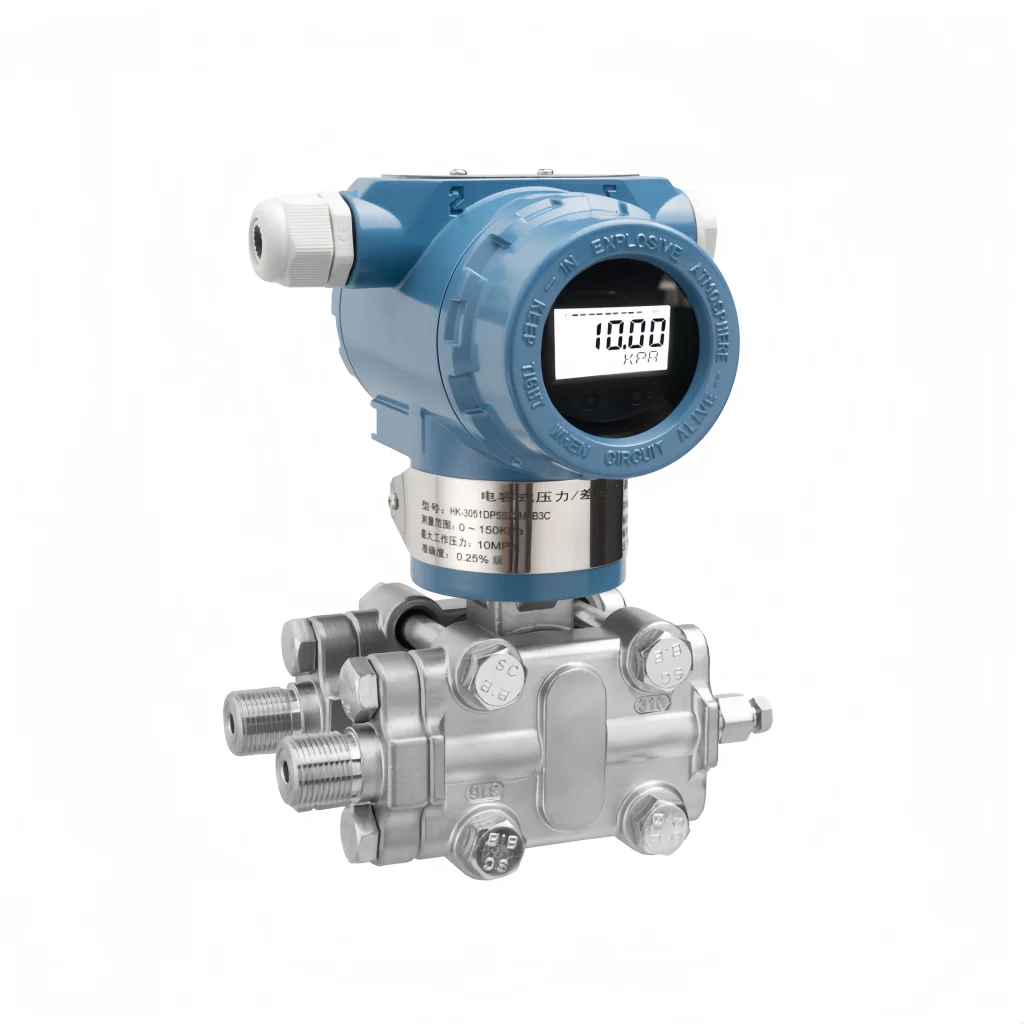
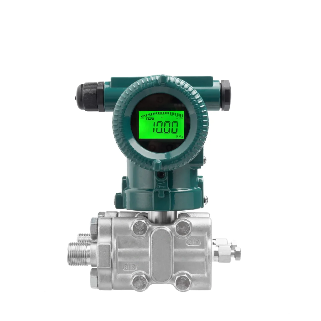
Bracket MountingThis is the most common installation method, whereby the differential pressure transmitter is secured to a wall, column or equipment bracket using a specialised bracket. It offers flexible installation and ease of maintenance, is suitable for most standard operating conditions, and effectively minimises the impact of pipe vibration on measurements.
Pipe Mounting
The transmitter is secured directly to horizontal or vertical process pipes or pressure-conducting pipes using pipe clamps. This method is simple to install and takes up minimal space, making it ideal for scenarios where space is limited and on-site wiring is restricted.
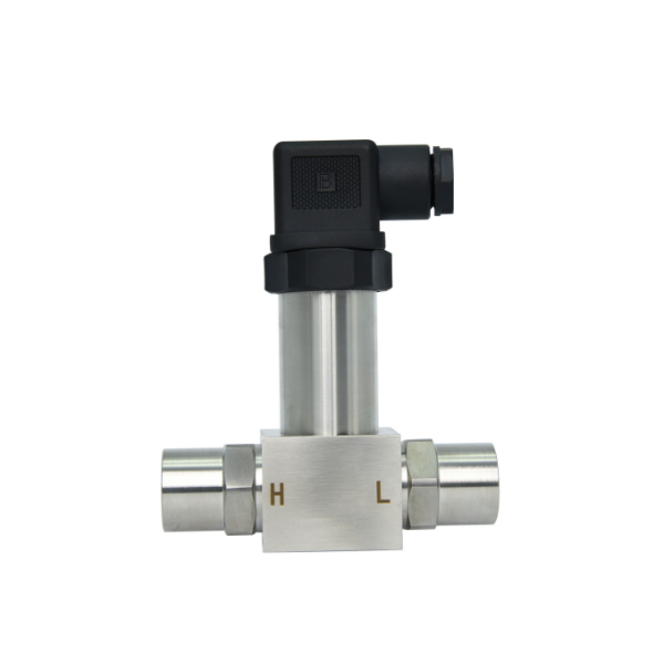
Flange Mounting
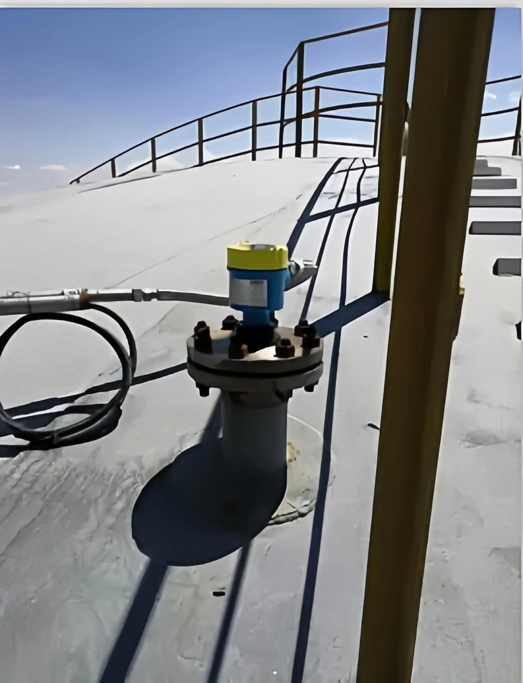
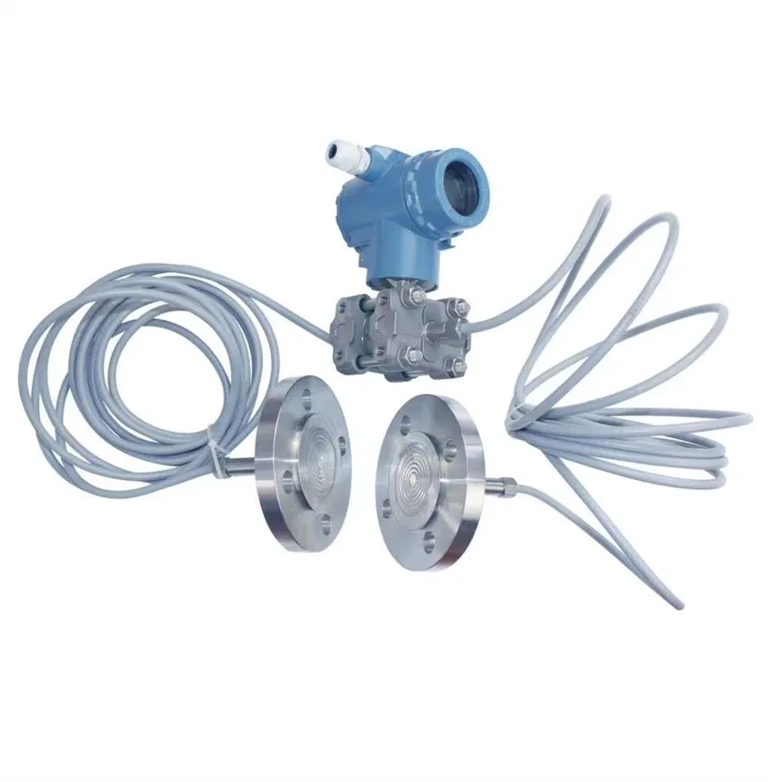
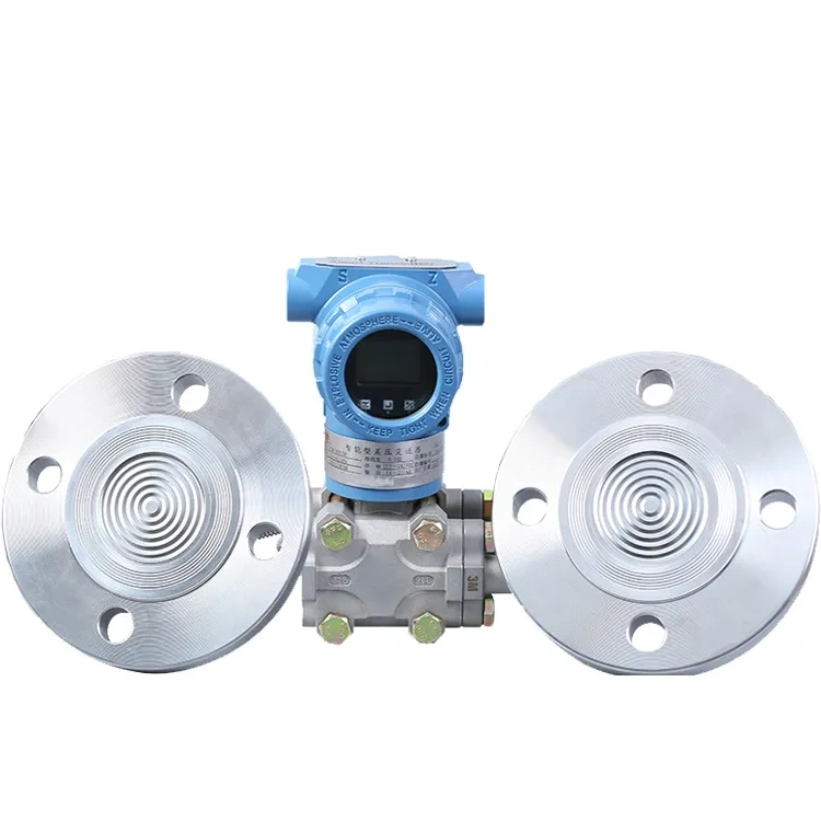
This method is primarily used for dual-flange differential pressure transmitters. It involves mounting the diaphragm seal directly onto the pressure-taking flanges of tanks or pipes, thus eliminating the need for pressure-taking lines. It is suitable for level and differential pressure measurement of viscous, crystallising, highly corrosive and high-temperature media.
Wall-Mounted Installation
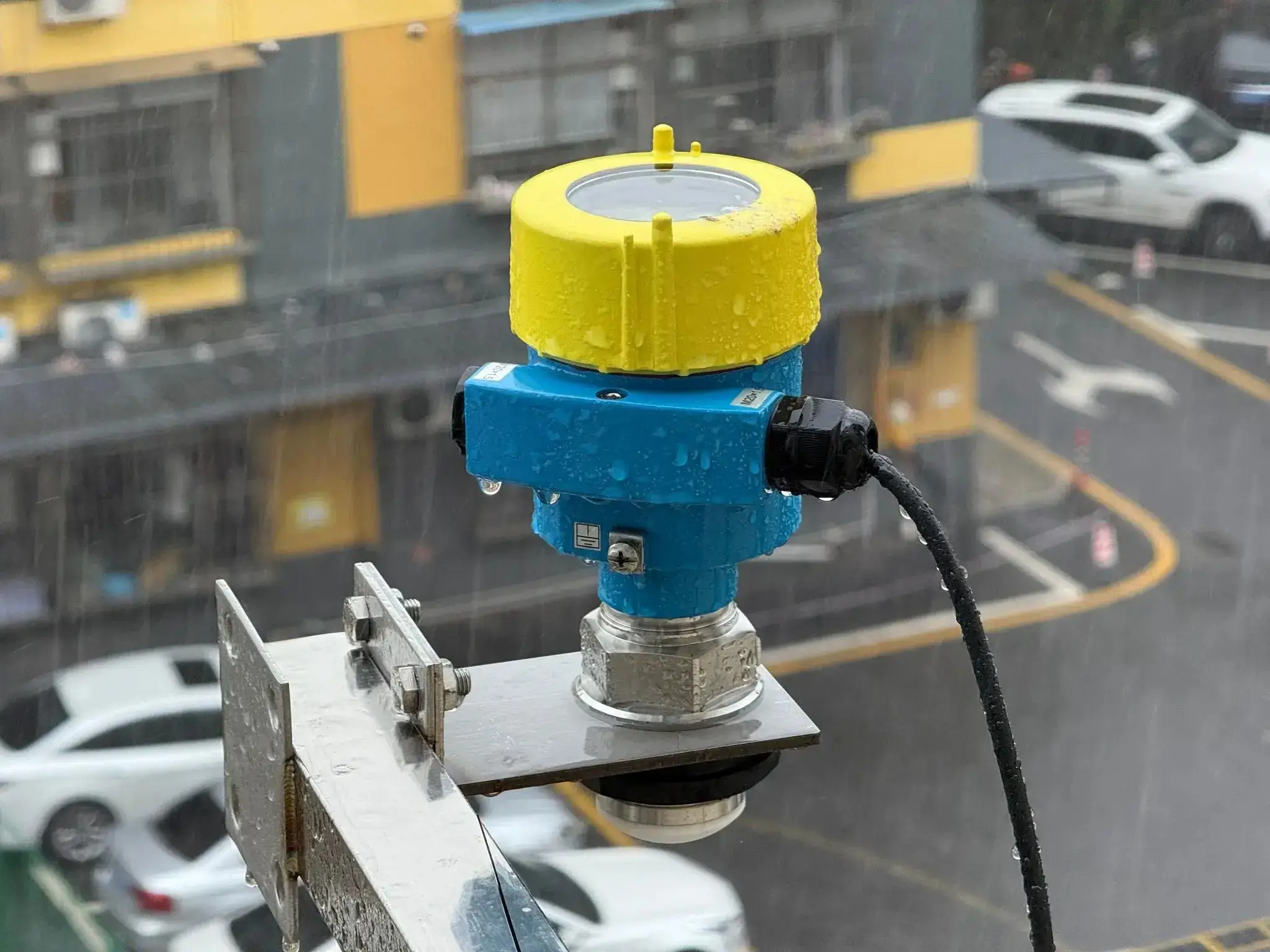
The transmitter base is secured directly to a wall or platform using bolts, providing a stable structure and a secure installation. This method is suitable for fixed-point installations in outdoor environments or on-site instrument enclosures.

5 Key Considerations Before Installation — Consolidating All Decisions
1. So, based on the operating conditions, can you work out the differential pressure transmitter’s range, pressure rating and protection rating? And can you then assess whether it can meet the requirements of the on-site pressure, environment and application?
2. Based on the medium temperature, decide whether to configure a condenser, heat dissipation components or a high-temperature transmitter, and determine the temperature protection method for the measurement loop and the diaphragm resistance scheme.
3. So, based on the installation height, just calculate the static pressure differential and level measurement error, and then you can work out the routing of the pressure leads and where the venting and draining will be. Then you can decide on the transmitter mounting position and zero-point compensation method.
4. Based on process operation and maintenance requirements, determine whether to use a two-valve, three-valve or five-valve manifold; decide on the operational structure for commissioning, calibration, purging and pressure relief of the transmitter.
5. Based on the control system and power supply method, determine whether to use a two-wire 4–20 mA, HART, bus or other wiring configuration, and decide on the transmitter’s power supply circuit, signal transmission and terminal block configuration.
How to Select a Suitable Installation Location for a Differential Pressure Transmitter
When choosing where to install a differential pressure transmitter, it is best to opt for areas with minimal vibration and no strong electromagnetic interference, which are also easily accessible for maintenance and servicing. Avoid high-temperature, corrosive, flammable or explosive environments. When measuring liquids, position the transmitter below the pressure tapping point. For gases, position it above.
For steam media, a condensation device must be provided, and the transmitter must be kept away from heat sources. The high- and low-pressure supply lines should be short, straight, of equal length, and exposed to consistent ambient temperatures. When you’re installing this outdoors, make sure you protect it well against rain and dust, but also make sure the locati0n lets air circulate and drains away liquid. This’ll help keep the equipment stable and last longer.
Installation steps for differential pressure transmitters
1. Secure the transmitter bracket:Use a spirit level to make sure the bracket is installed straight, then tighten the bolts to secure it and stop it from wobbling.
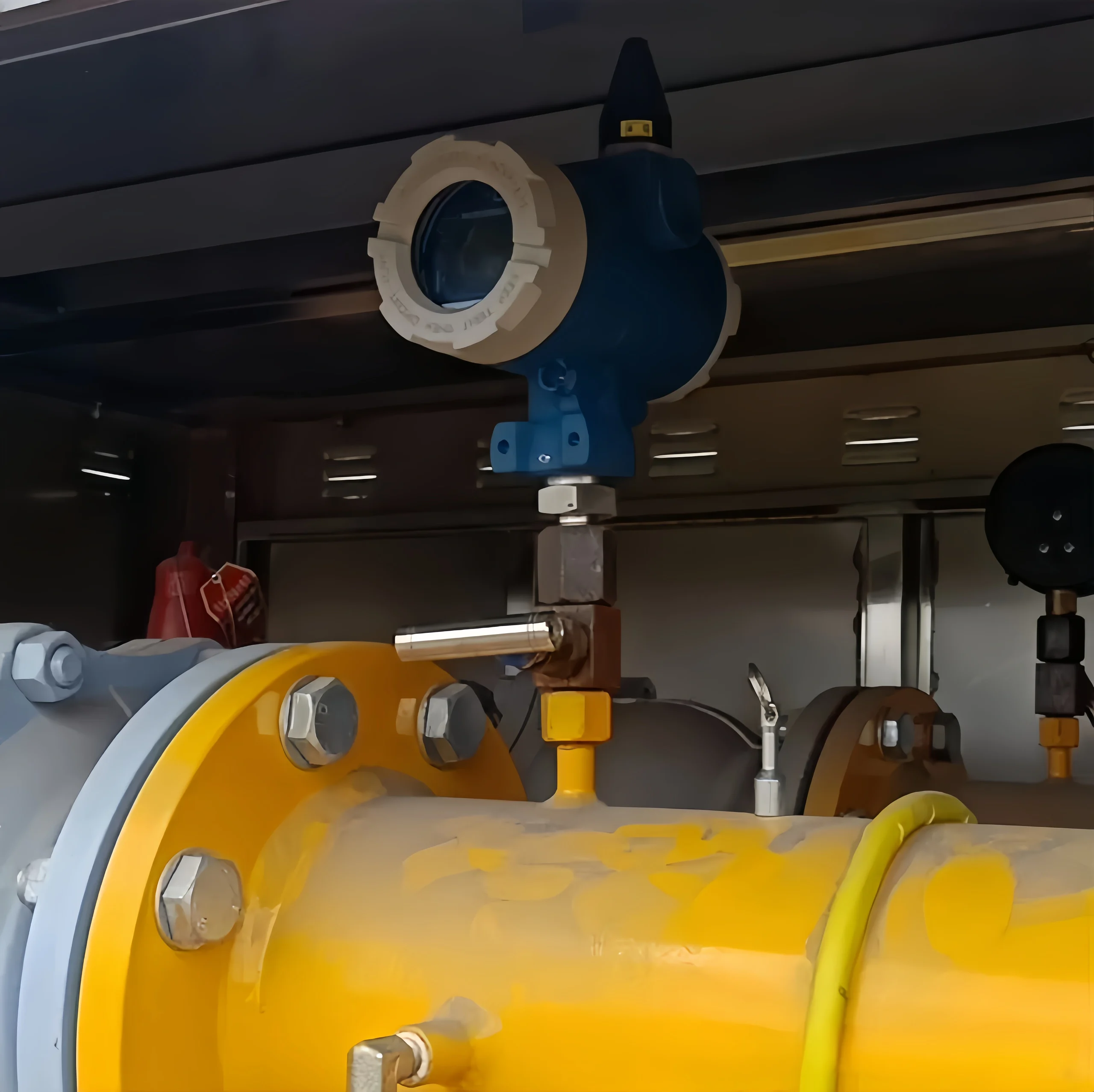
2. Install the three-valve manifold:Connect the three-valve manifold to the transmitter. Before installation, ensure the manifold is in the correct configuration: the high-pressure valve and low-pressure valve must be closed, whilst the balancing valve must be open. This prevents damage to the transmitter diaphragm caused by pressure surges on a single side.
3. Connect the pressure-taking lines: Strictly distinguish between the high-pressure and low-pressure side connections, and connect the pressure-taking lines correctly in accordance with the process flow direction; if measuring a liquid medium, the pressure-taking line must be sloped downwards to facilitate drainage; if measuring a gaseous medium, the pressure-taking line must be sloped upwards to facilitate venting; once the connection is complete, check that the sealing gaskets are properly seated to prevent medium leakage.
4. Auxiliary treatment for special media:If measuring high-temperature media, a condenser must be installed; if measuring viscous or crystallising media, an isolation tank must be installed and filled with isolation fluid to ensure the media does not come into direct contact with the transmitter, thereby preventing equipment damage.
5. Electrical Wiring:Make sure you connect the power and signal cables correctly, following the transmitter’s wiring labels. Use shielded cables wherever possible and ensure the shielding is properly earthed at one end. Once you have finished wiring it, seal the junction box to prevent moisture and dust from affecting how the equipment works.
6. Pre-commissioning Valve Check: Make sure you close all the relevant valves to get ready for pressure commissioning.
7. Pre-treatment of pressure piping: Open the two main valves on the positive and negative pressure sides. Next, open the balancing valve. Wait for the steam in the pressure piping and the condensate tank to condense completely.
8. Drainage and venting on the positive pressure side: Open the auxiliary valve on the positive pressure side and the drain screw in the positive pressure measurement chamber. Keep draining until only air-free condensate is discharged. Then close the drain screw in the positive pressure measurement chamber.
9. Drainage and venting on the negative pressure side:Open the drain plug on the negative pressure measurement chamber and continue draining until air-free condensate is discharged; then close the auxiliary valve on the positive pressure side. Next, open the auxiliary valve on the negative pressure side until air-free condensate is discharged from the drain plug on the negative pressure measurement chamber; then close the drain plug on the negative pressure measurement chamber and the auxiliary valve on the negative pressure side.
10. Instrument commissioning and inspection:Reopen the auxiliary valve on the positive pressure side, check the entire piping system for leaks, and verify that the instrument zero point is correct.
11. Completion of installation:Just close the balancing valve, then fully open the auxiliary valves on both the positive and negative pressure sides. The differential pressure transmitter’s now been installed and is good to go.
Commissioning and Calibration Following Installation
Once installation is complete, the differential pressure transmitter must be commissioned and calibrated to ensure that its measurement accuracy and stability meet the design requirements.
1. When you’ve finished the installation, first have a look to check the piping and make sure the transmitter’s in the right position, that the pressure tubing isn’t leaking, the valve positions are correct, the three-valve manifold’s working in the right order, the high and low-pressure sides aren’t connected in reverse, and the electrical wiring’s secure with shielding and earthing in line with standards, so you can be sure external interference won’t mess up the measurements.
2. Perform zero-point calibration. With the piping depressurised and the system in a pressure-balanced state, access the parameter settings interface via the transmitter’s buttons or a handheld programmer to execute the zero-point reset operation. Ensure that the output signal stabilises at the standard initial value under no-load conditions, whilst observing that the displayed value does not drift. If a slight deviation is present, it may be corrected directly.
3. Carry out span calibration. Apply standard pressure signals bit by bit, following the transmitter’s rated span. Put in pressures at zero, halfway, full and typical operating conditions, one after the other. Record the output current or digital signal, compare the standard values with the actual measured values, and calculate whether the error is within the allowed range.
4. Check linearity and hysteresis error. Keep a record of the data at each calibration point when the pressure is increasing and also when it is decreasing. Have a look at the measurement curve to see if it’s smooth and check that the hysteresis deviation is less than the limit. If it’s not linear, use the device’s built-in calibration function to fix it. This’ll make sure the measurements are spot on across the whole range.
5. Perform offset adjustment on differential pressure transmitters with offset correction capability. Set positive or negative offset parameters based on actual operating conditions such as on-site installation height and medium density. After completion, recalibrate the zero point and span to ensure that the measurement results accurately reflect the differential pressure in the pipeline following offset correction.
6. Calibrate for communication and remote transmission. Use a handheld programmer or control system to ensure the values displayed locally and remotely are identical. Ensure that the signal is sent and received without any issues, such as packet loss or changes in signal strength. This will help you to communicate normally with systems like DCS and PLC.
7. Try it out in real-world conditions. Open the process valves to introduce the actual medium pressure and observe the transmitter’s operational status. Monitor continuously for a period of time. Ensure there is no zero-point drift or span shift. Once the measured values are stable and reliable, complete the overall commissioning process.
How to Calibrate a Differential Pressure Transmitter
Preparation: Switch off the power supply and ensure that the differential pressure transmitter is securely installed, that the pressure tubing is free from leaks and blockages, and that the three-port valve assembly is in good working order. Prepare a standard pressure source, a handheld programmer or a multimeter, and record parameters such as the measurement range and units.
Zero Point Calibration: Open the balancing valve and close the high- and low-pressure valves to equalise the pressure in the transmitter’s positive and negative pressure chambers. The output should now be 4 mA. If there is a significant deviation, use the transmitter’s zero adjustment knob or the handheld programmer to adjust it until the output reaches 4 mA.
Full-scale calibration: Apply the standard pressure and check that the output is 20 mA. If this is not the case, adjust the range knob or change the range settings using the handheld programmer to make sure the full-scale output is accurate.
Mid-point verification: Apply 25%, 50% and 75% of the full scale range of pressures, respectively, and check that the corresponding output currents are 8 mA, 12 mA and 16 mA, respectively. If the linear deviation exceeds the limit, refine-tune the zero and span.
Re-inspection and Finalisation: Once the air has been released, check the zero point again. Then, close the balancing valve and fix the three-valve manifold so that it is working correctly. Next, record the calibration data and attach the calibration label. Finally, finish the calibration report.
Problems caused by incorrect installation of the differential pressure transmitter
Abnormal measurement data may result in readings that are too high or too low, poor linearity, zero drift, or significant fluctuations. In severe cases, there may be no display or the output may remain fixed, failing to accurately reflect the actual differential pressure.
The transmitter body is susceptible to damage. Issues such as unidirectional pressure surges, direct contact with high-temperature media, or water ingress due to poor sealing can cause diaphragm deformation or failure, as well as internal component faults, thereby shortening the instrument’s service life.
There is a risk of leakage and blockage. Poor sealing at flanges and connectors can lead to media leakage, whilst improper installation of pressure-taking tubes may result in air or liquid pockets. In low-temperature environments, freezing blockages may occur, affecting the flow of the measurement circuit.
Abnormalities in circuitry and signal transmission: Incorrect wiring, non-compliant earthing, and inadequate shielding can lead to signal interference, open circuits or short circuits, resulting in no output, signal fluctuations, or even damage to the transmitter circuitry.
For a differential pressure transmitter to work as well as it should, it must be installed correctly. It also needs to be high-quality to make sure that the measurements are accurate and it is reliable. Sino-Inst is a company that specialises in measuring industrial pressure. They offer differential pressure transmitters with a variety of connection options.
These cover standard operating conditions and special environments, such as highly corrosive or high-temperature conditions. This means they meet the needs of many different industries, including petrochemicals, power generation, metallurgy and water treatment.
Our products are stable, accurate and we provide great after-sales support. This means we can provide reliable measurement solutions for your production processes. Should you require advice on product models, customised solutions or professional technical support, please do not hesitate to contact us.