Radar level transmitters are workhorse instruments in industrial process control, yet they drift over time like anything else mechanical. Botch the calibration and you don’t just get bad readings—you’re looking at tank overflows or pumps running dry, neither of which ends well.
This guide covers the standard calibration steps and field commissioning tricks for radar level transmitters, aimed at getting your measurements back on track without the usual headaches.
What is a Radar Level Transmitter
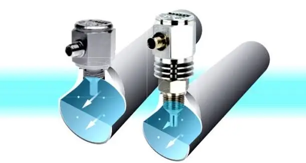
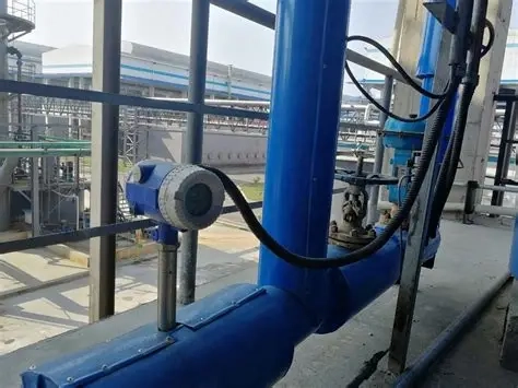
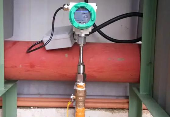
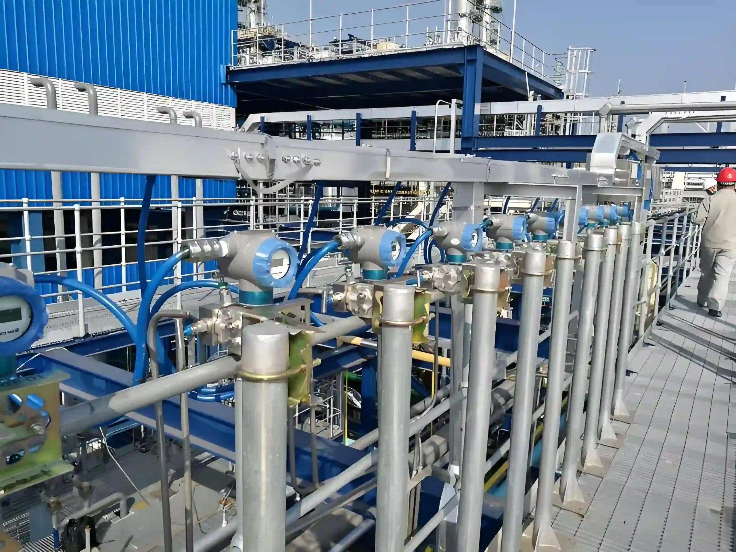
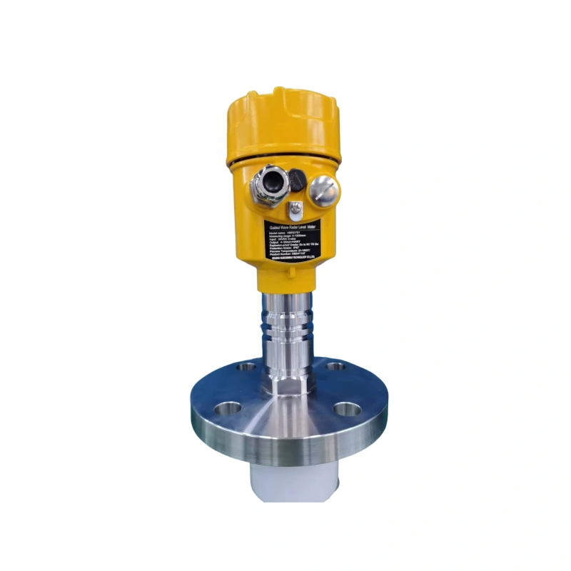
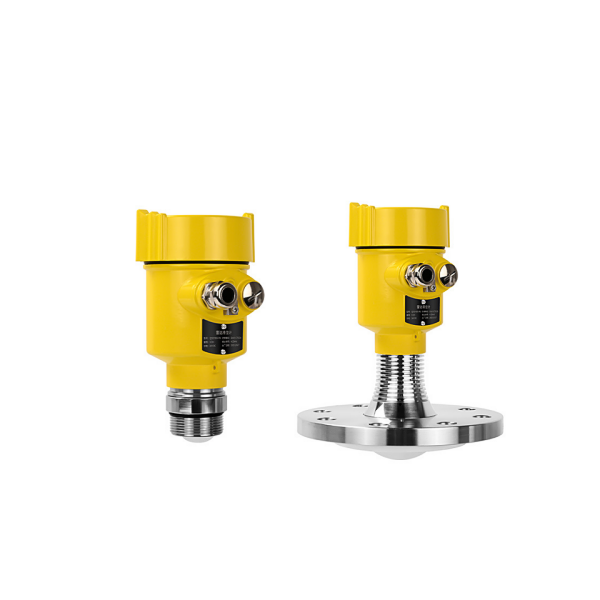
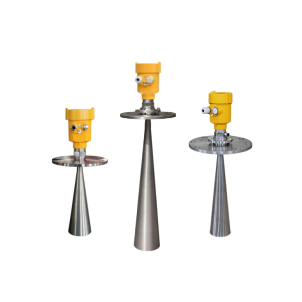
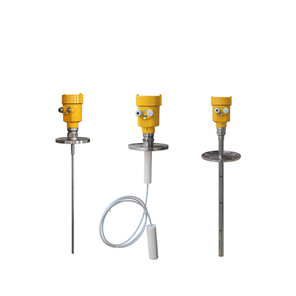
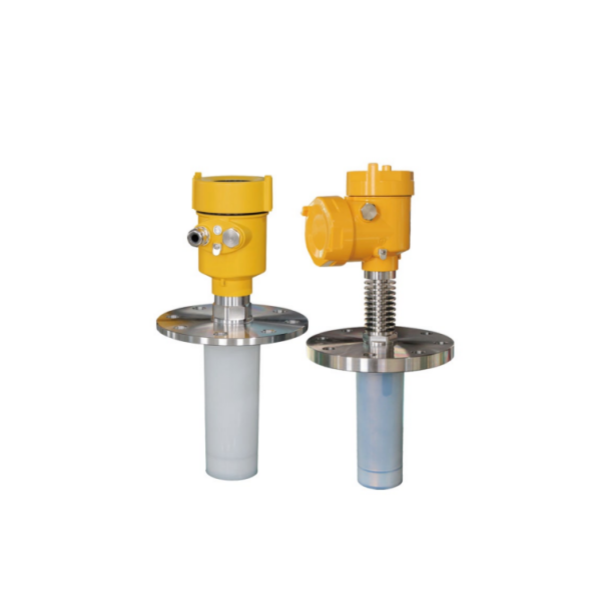
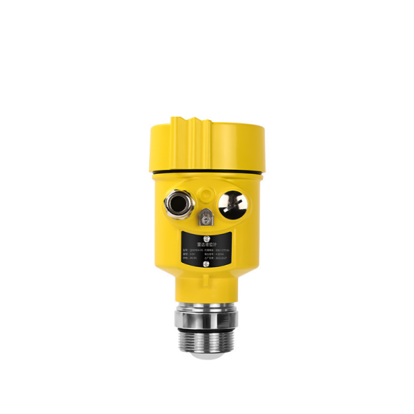
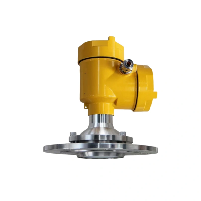
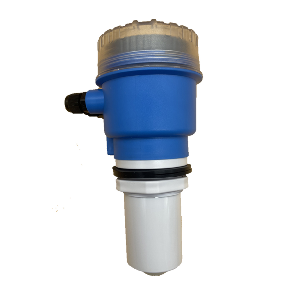
A radar level transmitter is an industrial level measurement instrument developed using radar ranging technology. As a non-contact measurement device, it is commonly used in various applications such as storage tanks, silos and reactors.
They can detect the level of liquids, slurries and granular materials within containers in real time, converting the measurement signal into a standard electrical signal for transmission to the control system. Combining high measurement accuracy with strong adaptability, and being unaffected by medium temperature, pressure, steam or dust, they are the mainstream liquid level monitoring equipment in industrial settings.
Working Principle of the Radar Level Transmitter
The radar level transmitter emits high-frequency electromagnetic waves via an antenna. These waves propagate through space at the speed of light, reflect upon contact with the surface of the material being measured, and the resulting echo is then received by the instrument’s antenna.
The instrument’s internal circuitry precisely calculates the time difference between the transmission and reception of the electromagnetic waves. It uses the speed of light to work out the actual distance from where the instrument is mounted down to the material surface.
This gets combined with things like the total vessel height to figure out the real-time liquid level, which is then turned into a standard analogue or digital signal and sent out — completing the continuous measurement and transmission of the liquid level.

Preparations Before Calibration
1. Check what’s actually going on out there. Look at how the vessel is running, what it’s holding, and what the temperature and pressure are doing—make sure it’s safe to work on it live. If you need to shut it down, drain it, or move the level around, get with operations first and sort out the timing.
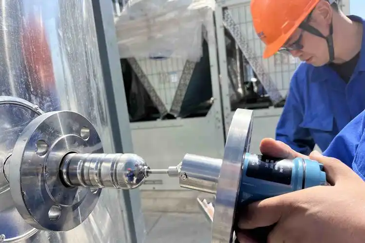
2. Give the hardware a once-over. Make sure the transmitter hasn’t worked itself loose, and that the antenna isn’t bent, caked with dust, gunked up with product, or corroded. Check that the cables are still in one piece and the terminals aren’t loose.
3. Round up your gear: handheld communicator, laser rangefinder, good tape measure, something to write on, and insulated tools. If you’re doing a reference-point cal, don’t forget the standard reflector.
4. Do the safety stuff properly—PPE on before you step in, solid platform if you’re working up high, and mind the fire and static rules if you’re out in the tank farm.
5. Hook up power and comms. Fire it up, check that the display isn’t flickering or cutting out, make sure you can talk to it, and confirm you can pull parameters and push changes through without any fuss.
6. Pull the old settings and history before you touch anything. Write down where the zero, span, deadband, tank height, and offsets currently sit—having that baseline makes it easy to see what changed once you’re done.
Calibration Procedure
Zero Calibration
1. Adjust the liquid level: Drain the tank of its contents to lower the liquid level to the device’s preset zero point. Leave it undisturbed for 3–5 minutes to allow the liquid level and the device’s measurement data to stabilise completely. Do not carry out calibration whilst the liquid level is fluctuating, as this may invalidate the calibration data.
2. Connect the commissioning equipment:Hook up the radar level transmitter to a handheld communicator. While you’re at it, grab a multimeter and hook it up to measure the transmitter’s analogue output current — keep an eye on both the measured level and the current as you go.
3. Perform zero point setting: Access the transmitter’s setup menu and locate the Zero Point Calibration or Empty Tank Calibration function. Make sure the tank is fully empty or exactly at the zero liquid level, then select Confirm to start the zero calibration process. The instrument will save the current status as its zero reference point.
4. Check the calibration outcome:Once zero calibration is completed, confirm the display shows 0%. Also check the output current, which should remain stable at approximately 4 mA under normal working conditions. If the readings are incorrect, repeat the zero calibration until all values are accurate.
5. Troubleshooting:If zero calibration keeps bombing out, check whether material is blocking the antenna or if there’s interference from echoes bouncing off the tank bottom. Clear whatever’s in the way and give calibration another shot.
Span Calibration
1. Adjust the liquid level:Fill the tank with the medium, slowly bringing the liquid level up to the full-scale position set by the process (maximum measurement level). Once it’s filled, let the system sit for 5 minutes so the liquid surface settles — no ripples, no splashing.
2. Verify Raw Data:Pull up the handheld communicator and check the transmitter’s current real-time measured level, percentage value, and analogue output current. Jot down the raw data before you calibrate anything — you’ll want it later for comparison.
3. Set the measuring range:Access the device commissioning menu and locate the Range Calibration / Full Tank Calibration option. Enter the actual liquid level value for full scale. Confirm the liquid has reached the maximum level, then run the range calibration.
4. Check range parameters: Once calibration completes, the on-site level reading should show 100% in normal operation, and the analog output current shall stay steady at 20 mA. If the displayed level does not match the output current, adjust the range settings and perform calibration again.
5. Test linearity: For accurate measurement verification, adjust the liquid level to 50% and 75% in sequence. Check if the corresponding analog output currents are 12 mA and 16 mA respectively.That’ll tell you if the device has any linearity drift.
Two Methods for Calibrating Radar Level Transmitters
Conventional Calibration
Conventional calibration is based on the physical reference of the tank, primarily involving the overall calibration of the zero point and full scale.
This generally requires shutting down the system and draining the medium from the tank, using the tank bottom as the zero point and the effective height of the tank as the full scale, to complete the two-point calibration in sequence.
This method constitutes a basic full-range calibration with a standardised operating procedure, and is commonly used for newly installed equipment, post-overhaul, and periodic comprehensive verification.
Reference Point Calibration
Reference point calibration relies on existing precise liquid level points at the site to correct deviations and is typically carried out online.
Known accurate liquid level positions, such as level gauges or standard sampling points, are selected and compared with the transmitter’s actual measurement data; measurement errors are then eliminated through fine-tuning of parameters.
This method does not require draining the medium or halting operations and is primarily used for accuracy verification and local error compensation whilst the equipment is in operation.
Differences between the two calibration methods
1. Different operational states.Routine calibration usually requires shutdown and draining of the medium, and is an offline operation; reference point calibration can be carried out whilst the equipment is in normal operation, and is an online operation.
2. Different calibration ranges. Routine calibration involves a complete calibration of the zero point and full scale, covering the entire measurement range; reference point calibration only corrects errors at the current single liquid level point, without altering the overall range parameters.
3. Different application scenarios.Conventional calibration is suitable for newly installed equipment, post-maintenance checks, and periodic comprehensive calibration; reference point calibration is suitable for routine accuracy checks during production and temporary deviation adjustments.
4. Different operational objectives.Conventional calibration focuses on re-establishing the entire measurement reference; reference point calibration focuses on comparative calibration to correct measurement deviations arising during operation.
Verification Following Calibration
Once calibration is complete, multi-point verification must be carried out to check the measurement accuracy of the equipment, ensure that on-site, equipment and central control data are synchronised, and guarantee the accuracy of the 4–20 mA signal output.
- Zero-point verification:With the liquid level at the zero-point reference level, the equipment should display 0% and the output current should be stable at 4 mA. If the data deviation is excessive, the zero-point must be recalibrated.
- Full-scale verification:Raise the liquid level to the full-scale position; once the liquid surface has stabilised, the device should display 100% and output a standard 20 mA current.
- Mid-range verification: Test at 25%, 50% and 75% liquid levels respectively; the corresponding outputs should be 8 mA, 12 mA and 16 mA. For standard equipment, the error should be controlled within ±1 mm.
- Stability and Archiving:Maintain a constant liquid level for 10 minutes; the device is deemed compliant if there is no data fluctuation or drift.
Routine Maintenance
Routine maintenance can effectively reduce measurement faults, extend the service life of the equipment, and prevent common issues such as signal interference and circuit faults.
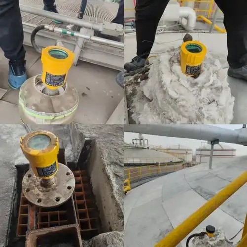
Antenna Maintenance: Clean dust, crystallisation, and stuck-on material off the antenna surface on a regular basis. If you’re dealing with condensation or viscous materials, step up the cleaning frequency. Don’t go at it with hard objects — you’ll damage the antenna.
Visual Inspection: Check that the equipment mounting bracket is fastened tight, with no rust or looseness anywhere. Make sure the protective cover is sealed up properly, and that the waterproof O-ring isn’t showing signs of ageing or damage. Keep the dust and water resistance intact.
Cable Maintenance: Check cables for signs of damage or wear, and ensure all terminal connections are secure and free of corrosion. For shielded cables, follow specifications to apply single-point grounding. When operating in corrosive conditions, apply anti-rust and protective treatments to all terminals.
Environment and Data: Clear all obstructions within the device’s measuring area. Keep the unit away from high-power motors and variable frequency drives to avoid electromagnetic interference. Routinely compare liquid level readings, and carry out repairs or recalibration promptly if any abnormal values appear.
Troubleshooting for Radar Level Transmitters
1. No echo; unable to detect liquid level
Causes: Dust, scale, or material caked on the antenna; something blocking the measurement area; bad grounding; electromagnetic interference kicking in.
Remedial Actions: Give the antenna probe a good clean; clear whatever’s in the way inside the tank; fix up the shielding wiring and make sure the equipment is properly earthed.
2. Fluctuating or erratic data, unstable readings
Causes: Liquid surface bouncing around too much; external electromagnetic interference; wiring that’s come loose or earthing done wrong.
Remedial Actions: Turn on the signal filtering function; tighten up those terminal connections; put in some baffle plates and steer clear of high-power electrical equipment.
3. Significant measurement errors; inaccurate readings
Causes: Parameters set up incorrectly; zero point or measurement range has drifted; transmitter installed at the wrong angle.
Remedies: Double-check the tank’s basic parameters; recalibrate the zero point and measurement range; adjust how the transmitter is mounted.
4. Abnormal 4–20 mA output signal
Causes: Abnormal supply voltage; signal line open circuit or short circuit; component failure.
Remedial Action: Check and stabilise the power supply; inspect and repair signal wiring; if the wiring is fault-free, replace the transmitter.
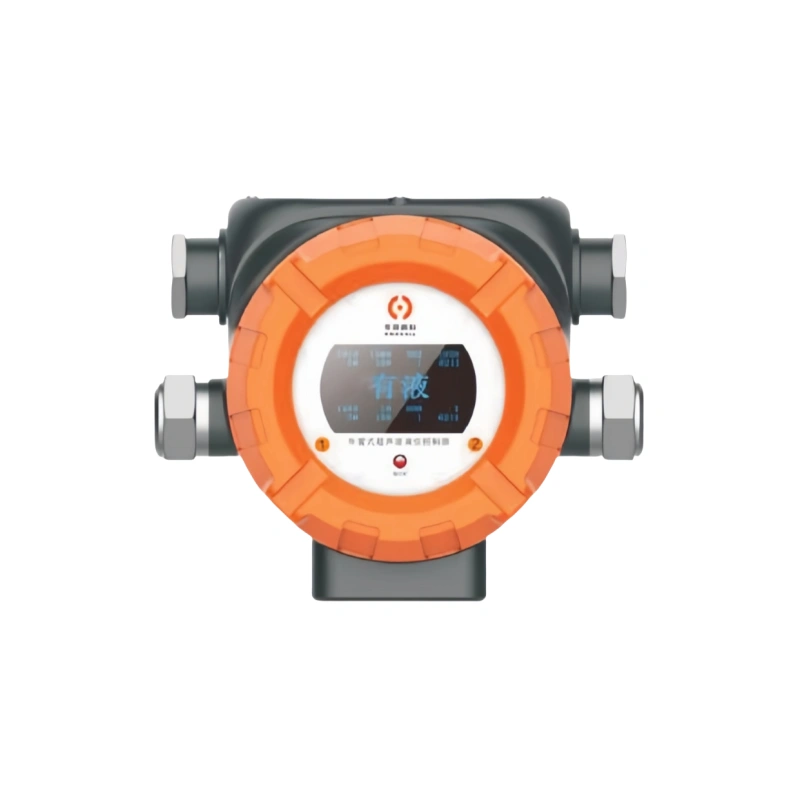
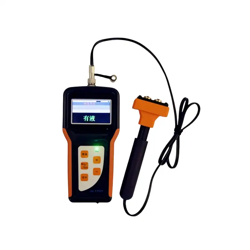
Sino-Inst supplies a full lineup of level transmitters to suit liquid level measurement needs across diverse industries and working conditions. Our product portfolio covers guided wave radar, non-contact radar, differential pressure, capacitive and ultrasonic level transmitters.
Our extensive product range is suitable for both simple, routine applications and complex, specialised conditions such as high temperature, high pressure and highly corrosive environments, covering the vast majority of industrial level measurement scenarios.
In addition, we provide customers with supporting technical services including equipment selection, on-site commissioning, fault repair and maintenance, and periodic calibration.