Magnetic Flow Meter Installation Guide

Table of Contents

A magnetic flow meter (magmeter) requires a full pipe and a stable flow profile to ensure measurement accuracy. Users should carefully consider installation details before purchasing a flow meter. For instance, the intended installation site must provide a straight pipe run of 5D upstream and 3D downstream (extending to 10D/5D following elbows or valves, and 15D after pumps). For other specific piping conditions, please refer to the guidelines below or contact our sales engineers for confirmation.

Sino-Inst Featured Products

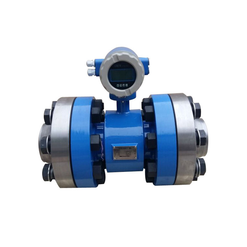
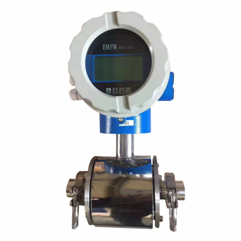
Integrated high-pressure flange connection electromagnetic flowmeter
High Pressure Magnetic Flow Meter
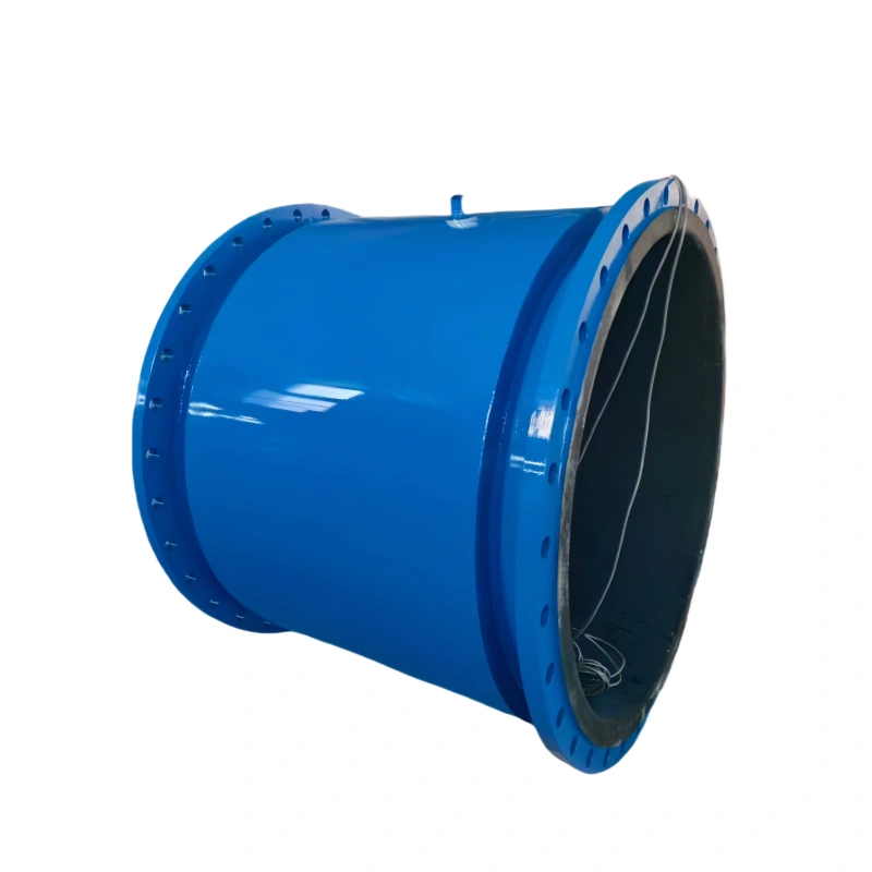
magnetic flow meter for large pipes
Magnetic Flow Meter for Large Pipes
battery-powered magnetic flow meter
Battery-Powered Magnetic Flow Meter
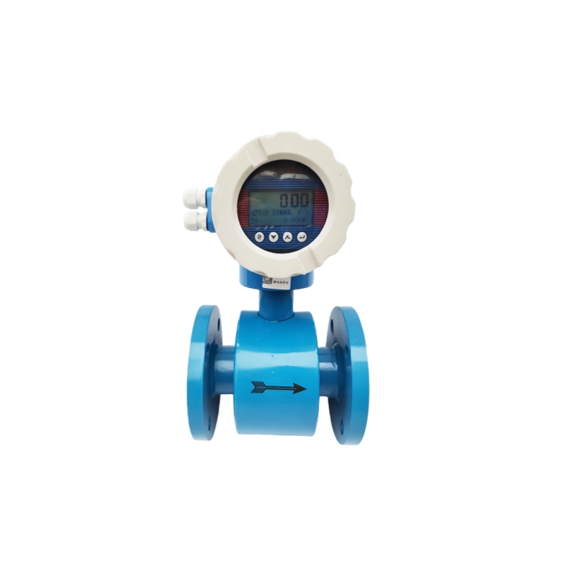
small-diameter magnetic flow meter
Small-Diameter Magnetic Flow Meter
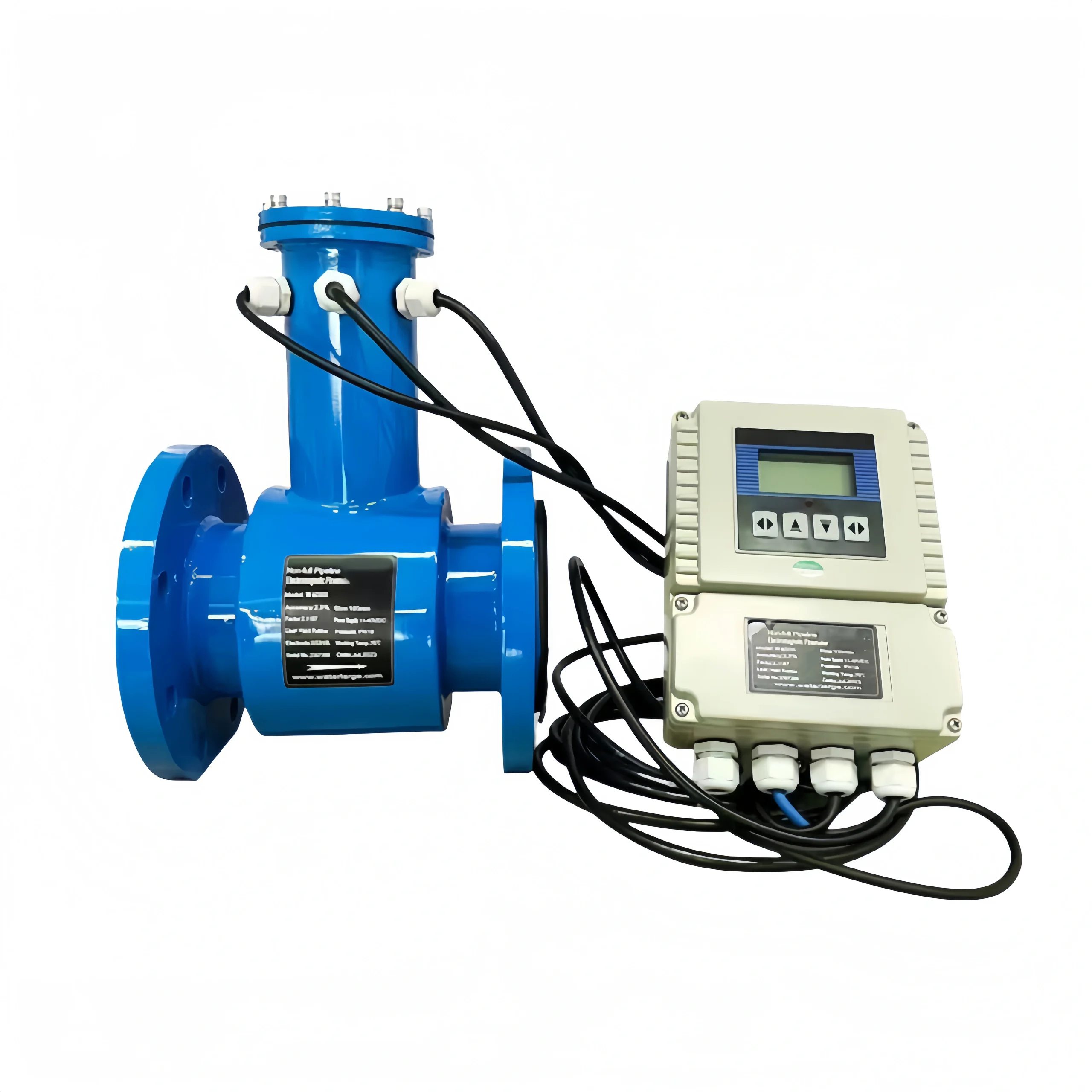
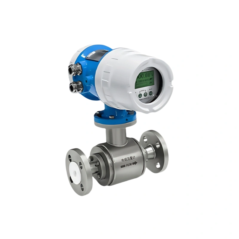
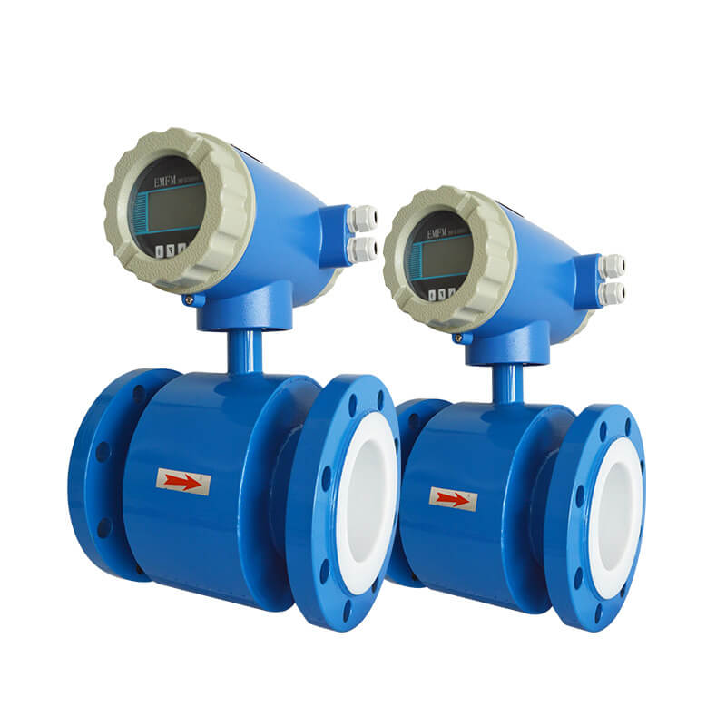
Inline Electromagnetic Flow Meter Split Type
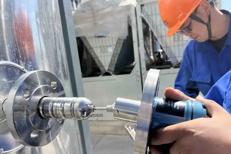
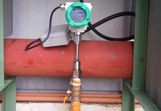
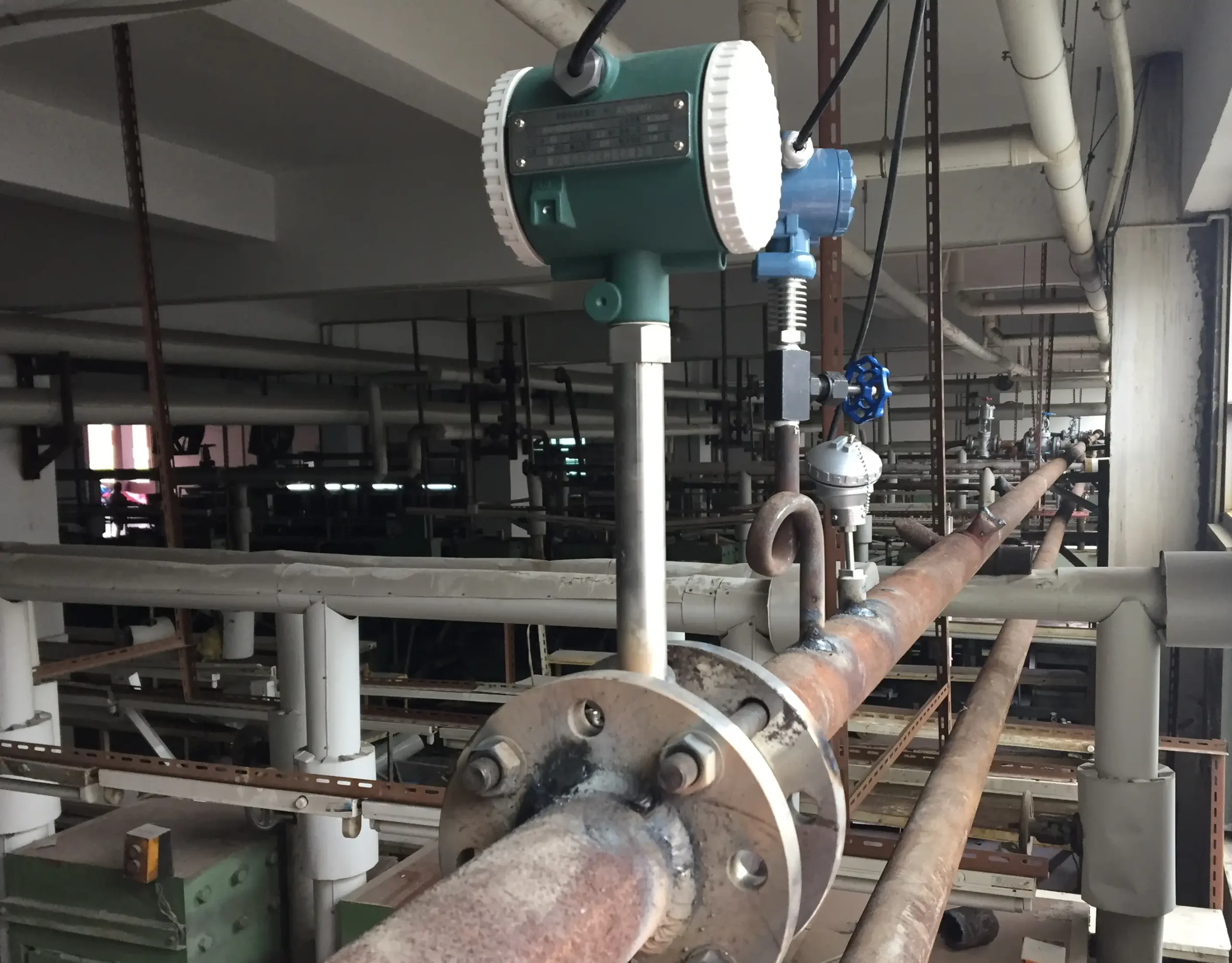
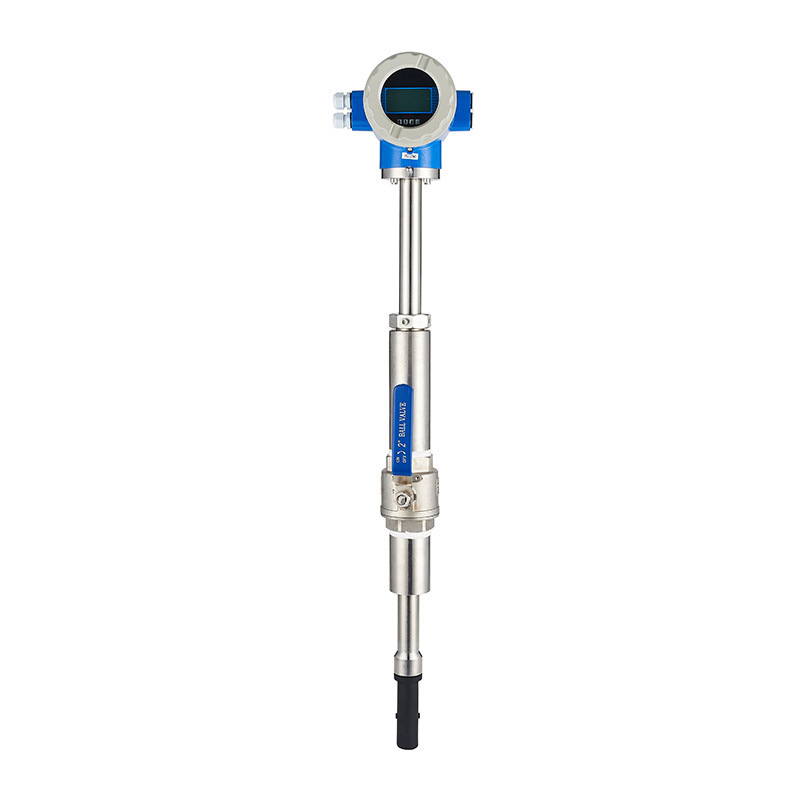
Insertion Magnetic Flow Meter with ball valve installation
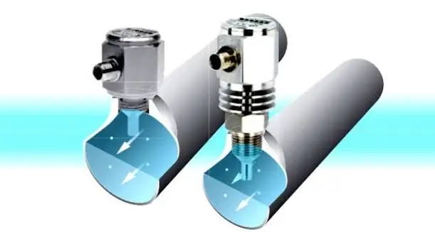
Insertion Magnetic Flow Meter | DN100~DN3000 Large Pipes

What are the Installation Environment Requirements for Magnetic Flow Meters?

a. The flow meter should not be installed in places where the temperature changes greatly or is exposed to high temperature radiation from the equipment. If it must be installed, insulation and ventilation measures must be taken.

b. The flow meter is best installed indoors. If it must be installed outdoors, it should be avoided from rain, water accumulation and sun exposure. Moisture and sun protection measures must be taken.

c. The flow meter should not be installed in an environment containing corrosive gases. If it must be installed, ventilation measures must be taken.

d. To facilitate installation, maintenance, there must be ample installation space around the flow meter.

e. The flow meter installation site should avoid strong magnetic fields and strong vibration sources. If the pipeline vibrates greatly, there should be supports on both sides of the flow meter to fix the pipeline.
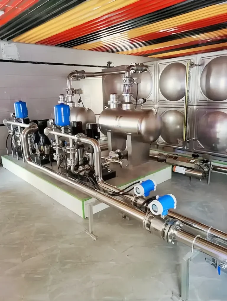
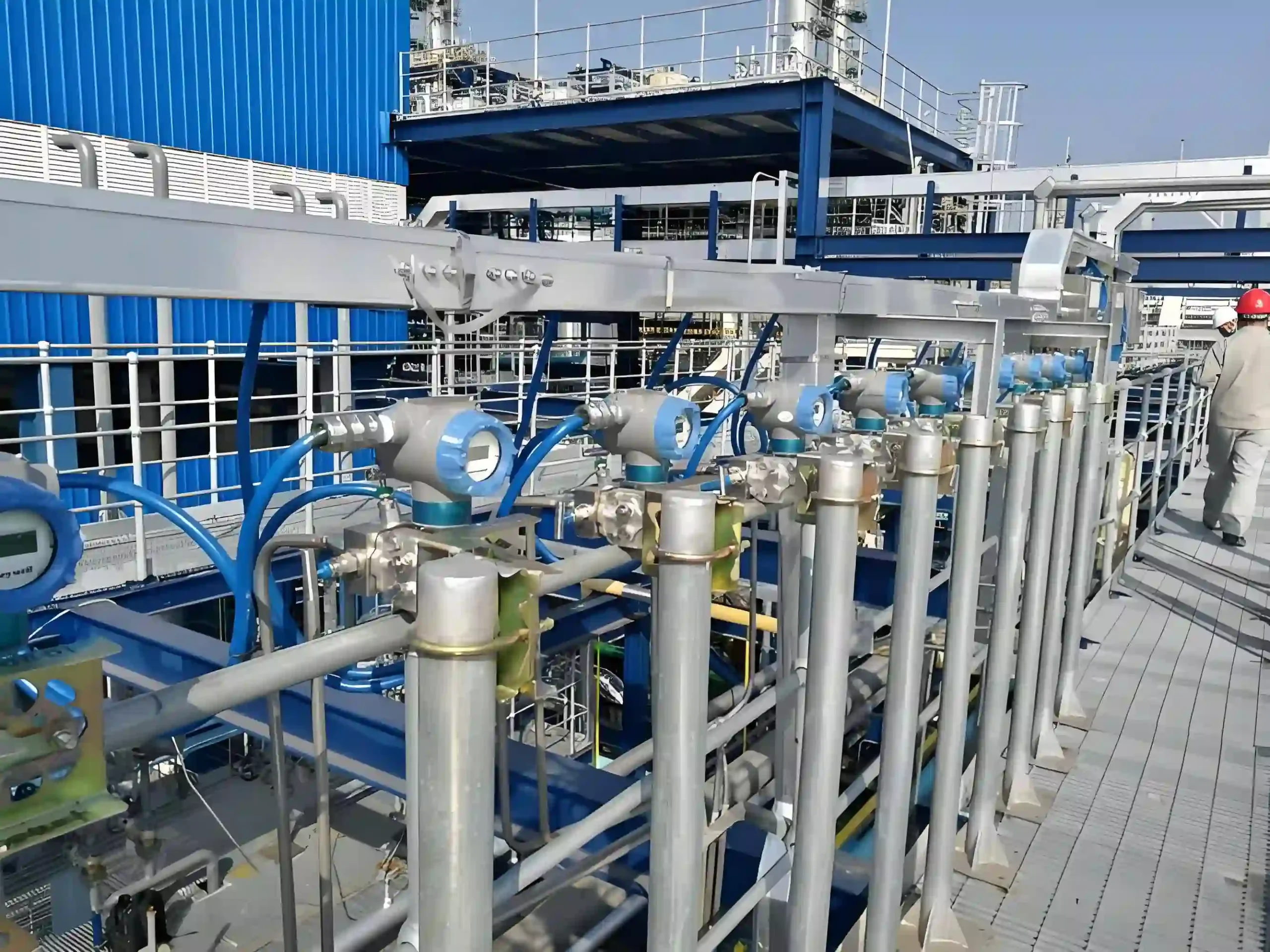
magnetic flow meters on the discharge line of a water booster pump skid

What are the Straight Run Requirements for Magnetic Flow Meters?

Straight pipe lets the flow profile settle before it reaches the electrodes. Elbows, valves, pumps and reducers upstream distort it. Minimum lengths in pipe diameters (D):
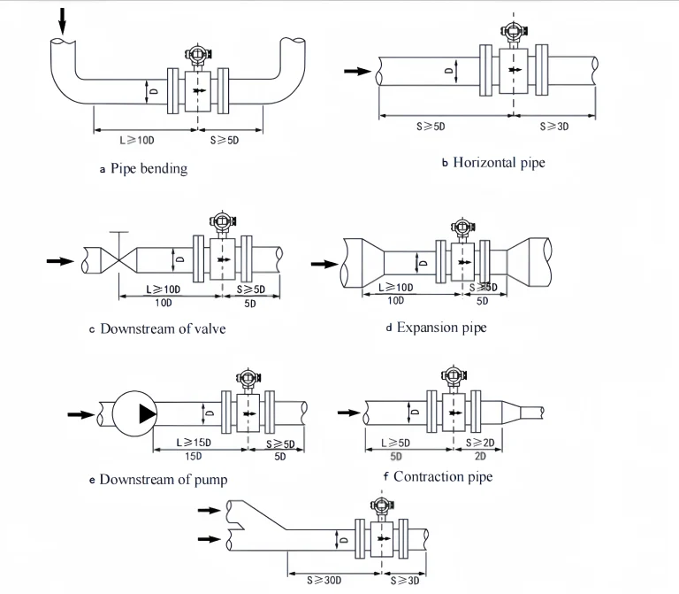
straight run requirements for a magnetic flow meter

Upstream of the meterDiagramUpstreamDownstream
Elbowa10D5D
Straight pipeb5D3D
Valvec10D5D
Expanderd10D5D
Pumpe15D2D
Reducerf5D2D
Mixing point (two lines joining)g30D3D

Rule of thumb: 5D upstream and 3D downstream; 10D after an elbow or valve, 15D after a pump. Where the full length won’t fit, a flow conditioner upstream can shorten it. Keep the meter away from control valves and partly open valves.

Requirements for Process Pipes

The flow meter has certain requirements for the upstream and downstream process pipes of the installation point. Otherwise, it will affect the measurement accuracy.

a. The inner diameter of the upstream and downstream process pipes is the same as the inner diameter of the sensor. And it should meet: 0.98 DN≤D≤1.05 DN

where:

DN: sensor inner diameter,

D: process pipe inner diameter)

b. The process pipe and the sensor must be concentric, and the coaxial deviation should not exceed 0.05DN.

What are Bypass Pipes Requirements of Magnetic Flow Meter?

In order to facilitate the maintenance of the flow meter, it is best to install a bypass pipe for the flow. In addition, for heavily polluted fluids and flow meters that need to be cleaned and the fluid cannot be stopped. A bypass pipe must be installed.
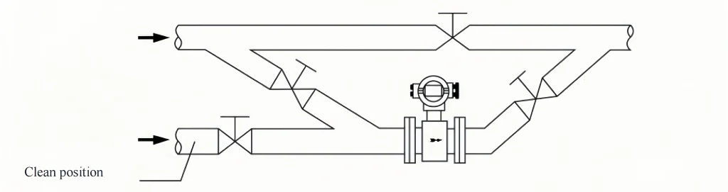
bypass line with isolation valves around a magnetic flow meter

Magnetic Flow meter Installation Requirements on Pipelines

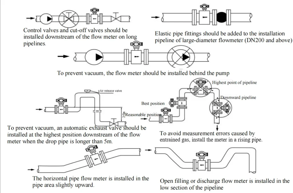
The measuring tube must run full: no trapped air, no vacuum.

  • Valves: control and shut-off valves go downstream of the meter.
  • Pumps: install on the discharge side, never the suction side. Vacuum pulls gas out of the liquid and can collapse a PTFE liner.
  • High points: avoid them, and avoid lines with downward flow — air collects there. A rising line is the best position.
  • Drops over 5 m after the meter: fit an air-release / vacuum-break valve at the downstream high point.
  • Open discharge: put the meter in a low section or U-bend so it stays full when flow stops.
  • Horizontal lines: choose a section that rises slightly in the flow direction.
  • DN200 and above: add a flexible (expansion) joint next to the meter.
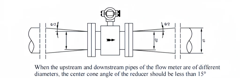
  • Reducers: cone angle below 15°.

magnetic flow meter piping layout rules

reducer cone angle for a magnetic flow meter

Sensor grounding

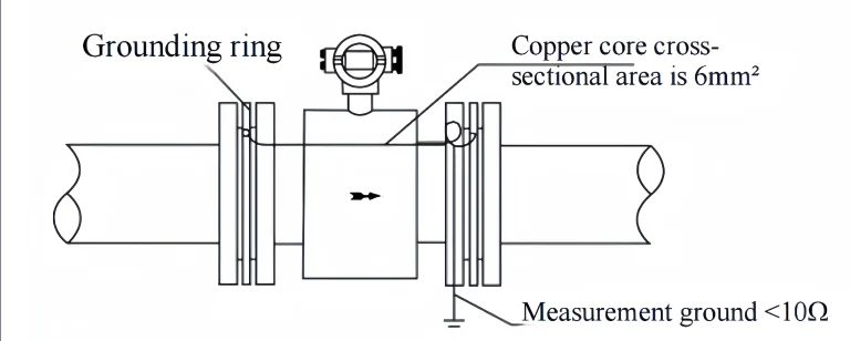
To make the instrument work reliably. The sensor should have a good separate grounding wire with a grounding resistance of <10Ω. If the pipe connected to the sensor is coated with an insulating layer or is a non-metallic pipe, grounding rings or built-in grounding electrodes should be installed on both sides of the sensor.

a. Grounding method on metal pipes: There is no insulating layer in the metal pipe, so ground it according to the figure below.

magnetic flow meter grounding on bare metal pipe, ground resistance below 10 ohm

                                                                                                                           Installation of the sensor on a metal pipe (without insulation layer on the inner wall)

b. Grounding method on plastic pipes or pipes with insulating layers or paint:

Grounding rings or built-in grounding electrodes should be installed on both ends of the sensor. The measured medium flowing in the pipe is short-circuited to the earth and has zero potential. Otherwise, the electromagnetic flow meter cannot work properly.
grounding rings on both ends of a magnetic flow meter in plastic or lined pipe

Installation of sensors on plastic pipes or pipes with insulation, oil and gas pipelines
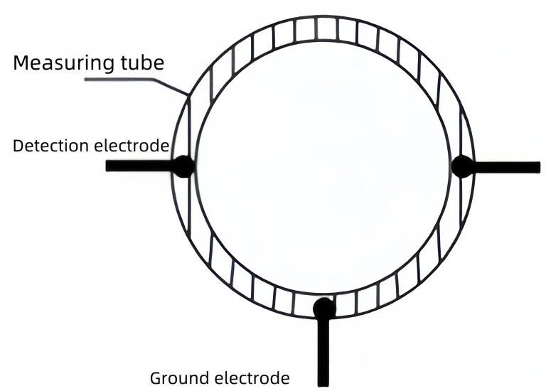
measuring tube cross-section with detection electrodes and grounding electrode

Note: If there is a grounding electrode in the sensor, there is no need to add a grounding ring. The function of the grounding electrode is the same as that of the grounding ring.

Sensor Installation on Cathodic Protection Pipes

Pipes that protect against electrolytic corrosion are usually insulated on their inner and outer walls because the measured medium has no ground potential. Therefore, the sensor must use a grounding ring or a built-in grounding electrode.

For pipelines with cathodic corrosion protection, the sensor and the connecting pipes on both sides are usually insulated. So, the medium is not conductive to the ground. Pay attention to the following points during installation:

a. The grounding rings should be installed on the two end faces of the sensor. They must be insulated from the flanges of the process pipeline and connected to the sensor through the grounding wire 2. The material of the grounding ring should be resistant to the corrosion of the medium. Standard rings are stainless steel (1Cr18Ni9Ti, similar to AISI 321); use 316L, Hastelloy or titanium for aggressive liquids.

b. Bridge the two pipe flanges with a copper cable of at least 4 mm², so the cathodic-protection current bypasses the meter. Do not connect this cable to the meter body or the grounding rings.

c. The flange connection bolts must be insulated from the flanges of the process pipeline. The user must prepare bushings and gaskets made of insulating materials. See the schematic diagram below for details.
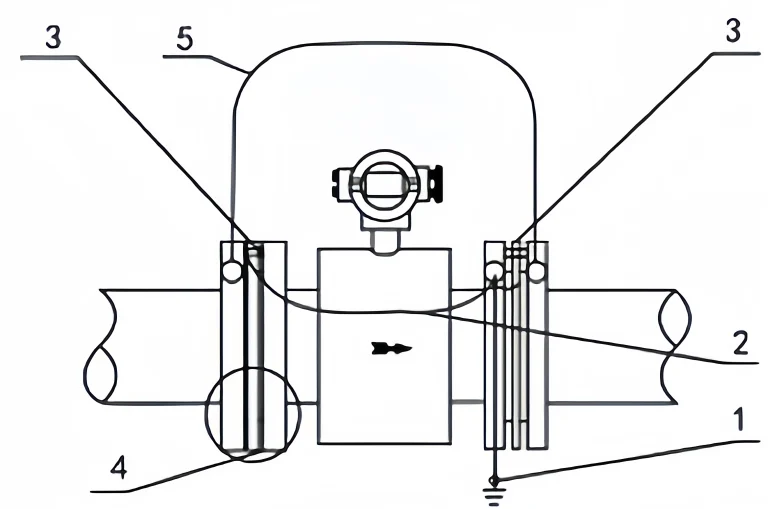
magnetic flow meter on a cathodic-protected pipeline with insulated grounding rings

  1. Measurement grounding <10Ω
  2. The cross-sectional area of the grounding wire copper core is 6mm²
  3. Grounding ring
  4. The bolts should be insulated from the flange during installation
  5.  The cross-sectional area of the connecting wire, copper core is >4mm²
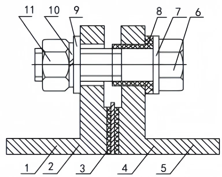
insulated flange bolt with isolating bushing and gasket

  1. Sensor 2. Lining (PTFE or F46) 3. Grounding ring 4. Insulating gasket  5. Pipe 6. Bolt 7. Washer 8. isolating bushing 9. Flat washer 10. Spring washer 11. Nut


Transport the Magnetic Flow Meter

Lift only by the lifting lugs on the flanges, with a sling on each side. Never lift by the converter, and never wrap slings around the meter body or flanges. Keep the flange covers on until installation — a damaged liner cannot be repaired on site.
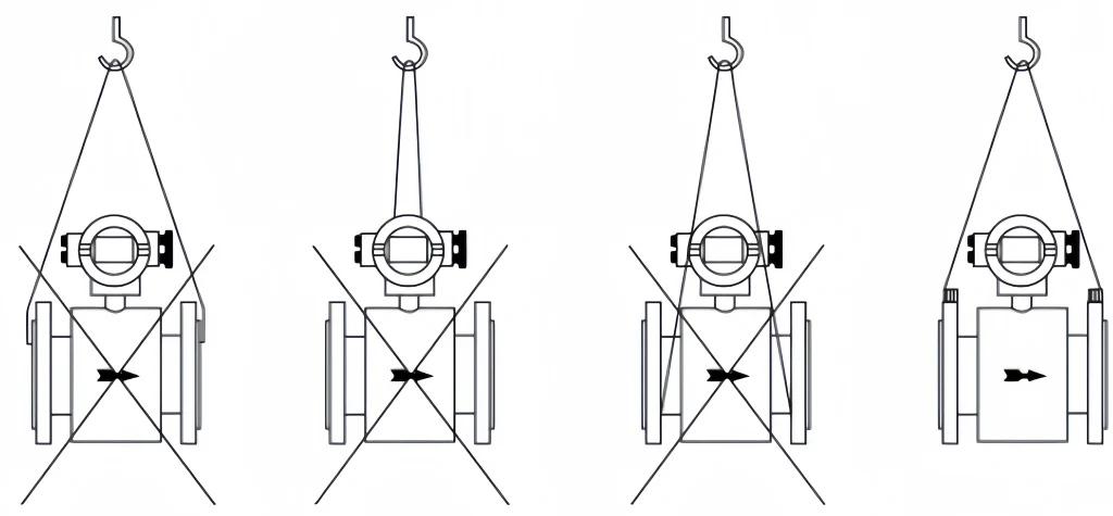
how to lift a magnetic flow meter

Precautions for Installing the Magnetic Flow Meter

a. The installation dimensions must be calculated accurately. Otherwise, it is easy to leak or fail to install.

b. The flow direction of the fluid must be consistent with the flow direction arrow on the sensor body.

c. The electrode axis of the flow meter must be approximately horizontal. Otherwise, it will affect the measurement accuracy.

d. The flanges on both sides of the sensor must be kept parallel. Otherwise, it is easy to leak.

e. To avoid the formation of vortex flow after installation. It should be ensured that the process piping and the coaxial connection of the flow meter cannot be staggered.

f. When installing the flow meter, it is strictly forbidden to weld close to the flow meter flange. Avoid burning the flow meter lining.

g. For process pipelines of different properties, the corresponding grounding method should be adopted (see sensor grounding)

h. For slurries, liquids carrying solids or gas, and slow lines, mount the meter in a vertical pipe with flow going upward. Solids can’t settle on the electrodes, gas can’t collect at the top, and the liner wears evenly.

i. For measuring tubes larger than 200 mm, fit a flexible (expansion) joint to make installation easier.
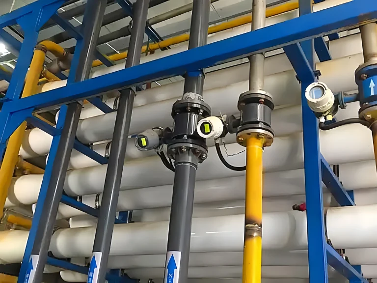

magnetic flow meters installed on vertical lines in a water treatment skid

The role of straight pipe runs is mainly reflected in the following aspects:

1. Stabilize fluid flow

When the fluid flows in the pipeline, it will be affected by various factors and produce instability. such as pipe bending, valve switching, pump operation, etc.

These unstable factors will cause uneven distribution of fluid velocity, vortex and turbulence, etc., thus affecting the measurement accuracy of the flow meter.

The straight pipe section can provide a certain buffering effect through its length. so that the fluid can tend to be stable after flowing through the straight pipe section. Reducing the impact of instability on the measurement.

2. Reduce fluid disturbance

Swirl from elbows in different planes decays slowly, so it needs a longer straight run than a single bend.

3. Ensure measurement accuracy

The measurement accuracy of the flow meter is one of its most basic requirements. The setting of the straight pipe section can ensure that the fluid is in a relatively stable state before flowing through the flow meter.

At the same time, the straight pipe section can also reduce the errors caused by factors such as improper installation position or unreasonable pipeline layout.

Magnetic flow meters are used mainly on water and wastewater, chemical, slurry, pulp and food lines. They need a conductive liquid — at least 5 µS/cm — so they will not measure oils, fuels or demineralised water.

Choosing a suitable magnetic flow meter can ensure the accuracy and efficiency of the production process. The following are the factors:

1. Measurement requirements

It is necessary to determine the type of fluid to be measured, flow range, temperature, pressure and other parameters. Ensure that the selected magnetic flow meter meets the actual measurement requirements.

2. Accuracy requirements

Standard accuracy is ±0.3% of reading at 1 m/s and above (DN15–DN600) and ±0.5% for DN700–DN3000. Below 1 m/s the error is a fixed velocity value, so size the meter to keep normal flow above 1 m/s.

3. Material selection

Choose the liner and electrodes for the liquid. Liners: PTFE, PFA, F46, neoprene and polyurethane. Electrodes: 316L for water and wastewater; Hastelloy, titanium or tantalum for acids, alkalis and seawater.

4. Output signal

4–20 mA and pulse output as standard; RS485 Modbus or HART on request.

5. Installation method

Flanged for process lines, sanitary tri-clamp for food and pharma, threaded for small bores, and insertion type for large pipes.

Send us the liquid, its conductivity, flow range, pipe size, pressure and temperature, and we will check the meter size and straight-run layout before quoting.

Coriolis mass flow meter, positive displacement flow meter:

No straight-run requirement in most cases.

Rotameter:

At least 5D upstream; no downstream requirement.

Target flow meter:

upstream straight pipe section is not less than 5 times the pipe diameter, and downstream is not less than 3 times the pipe diameter;

Turbine flow meter:

upstream straight pipe section is not less than 5 to 20 times the pipe diameter, and downstream is not less than 3 to 10 times the pipe diameter;

Vortex flow meter:

upstream straight pipe section is not less than 10 to 40 times the pipe diameter, and downstream is not less than 5 times the pipe diameter;

Magnetic flow meter:

5D upstream and 3D downstream on a straight run; 10D/5D after an elbow or valve, 15D after a pump (see the table above).

Ultrasonic flow meter:

The upstream straight pipe section is not less than 10 to 50 times the pipe diameter, and the downstream is not less than 5 times the pipe diameter.

The magnetic flow meter installation is a very complicated issue. If you encounter any problems during the installation process. Please feel free to contact us. Our professional engineers will solve the relevant problems for you.

Sino-Inst has more than 20 years of experience in flow measurement. Our products have been well-received by users around the world. If you need to buy a flow meter, you can choose us. Sino-Inst is your best flow measurement partner.

Welcome To Share This Page:
Product Categories
Latest News
Get A Free Quote Now !
Contact Form Demo (#3)

Related Products

Related News

There are two main types of electromagnetic flow meter: inline and insertion. Both of these work on something called Faraday’s law

Electromagnetic flow meters are devices that measure the flow of a liquid by using the principle of electromagnetic induction. They

Electromagnetic flow meters are an important piece of equipment for measuring flow in industry. The material used to line the

Magnetic flow meters are commonly used for flow detection of various equipment. They are widely used in many production enterprises

Magnetic flow meters utilise Faraday’s law of electromagnetic induction to measure the volume of conductive fluids without causing any pressure

Water is something we all need in our day-to-day lives and you can find it everywhere. In areas like modern

In industry, electromagnetic flowmeters are now the main way to measure conductive liquids because they don’t have pressure loss and

Electromagnetic flowmeters are instruments that measure the flow of fluids. They are used in many industries, including industry, chemistry and

Scroll to Top

Get A Free Quote Now !

Contact Form Demo (#3)