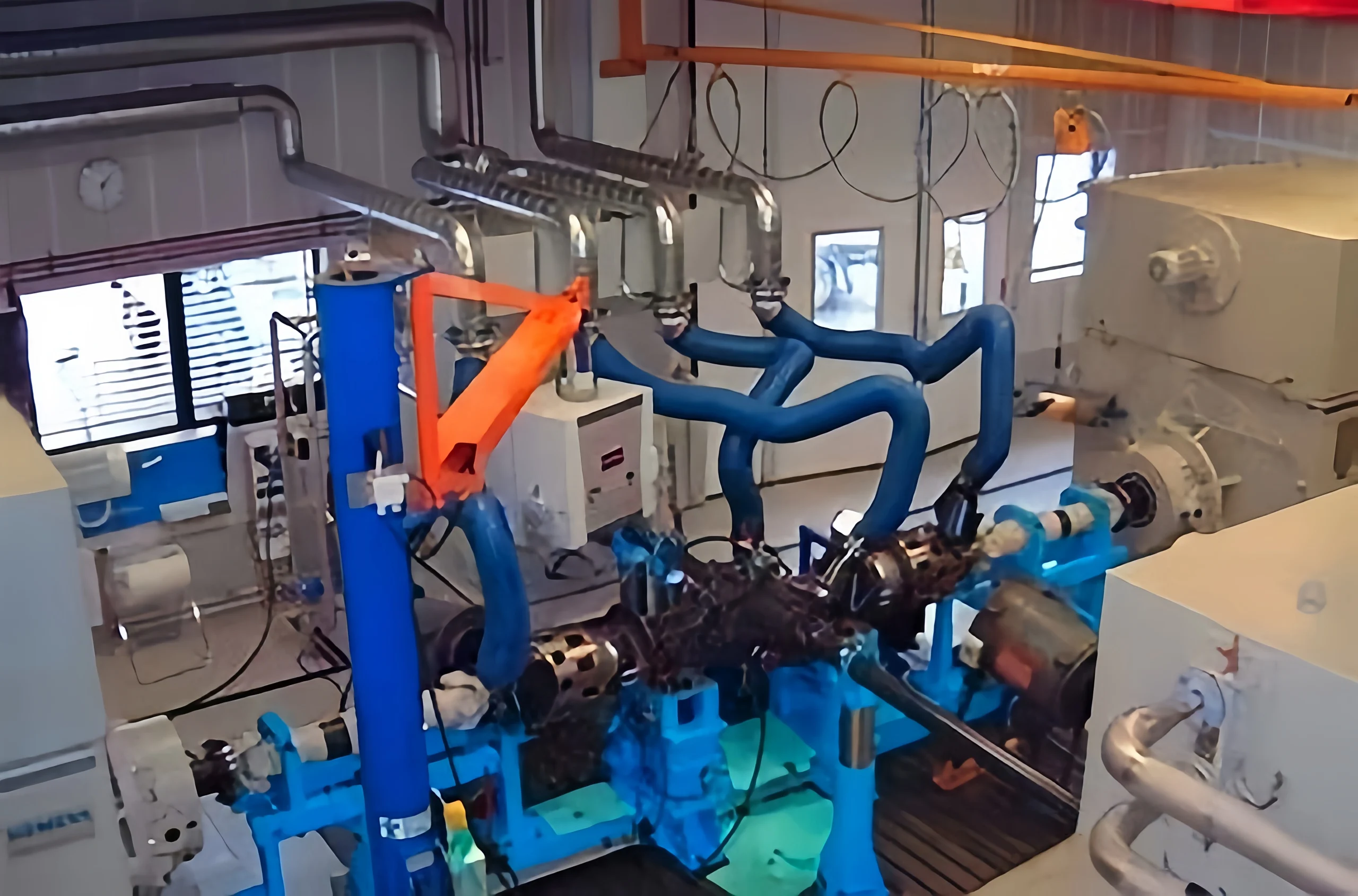
Both boilers and chemical production lines count on steam pressure transmitters to keep tabs on operating conditions, yet high-temperature steam brings its own set of installation headaches.
Even minor slip-ups in how pressure lines dissipate heat, where condensate traps sit, or which way the pressure taps face can throw off your readings. What follows lays out standard installation steps and the main protective measures drawn from field experience, aimed at cutting down on instrument wear and keeping measurement errors in check.
How Steam Pressure Transmitters Measure Steam
1. Steam temperatures run well beyond what standard transmitter diaphragms can handle, so the condensate trap is your first line of defense. During setup, put the trap at the highest point of the pressure line. Start by filling it with room-temperature condensate water.
When the hot steam hits, it condenses on contact with that cooler liquid. The water inside the trap acts as a buffer, blocking the steam and letting only water pressure through to the transmitter. This keeps the instrument from getting cooked and stops zero-point drift from creeping in.
2. Since there is a height difference between the pressure tapping point and the transmitter, a slope is maintained throughout the piping. The steam pressure tapping port should preferably be located on the upper half of the pipe to prevent backflow of condensed water from causing impact.
The pressure-taking pipe should slope slightly upward toward the condensate trap to ensure that all condensed water is stored within the trap, thereby preventing backflow and air locks.
3. Supporting valves are installed in this specific order: main isolation valve, condensate receiver tank, followed by a secondary three-valve set. This three-valve assembly serves test run, calibration and routine service work.
When carrying out commissioning work, start by opening the equalizing valve, then gradually crack open the high and low pressure isolating valves one after another, and seal the equalizing valve last. This order stops unilateral high pressure shock waves from damaging the sensor diaphragm. The whole operation sequence should be reversed when conducting equipment maintenance.
4. Standard pressure transmitters paired with condensate pots work well for saturated steam measurement. If dealing with superheated steam conditions, install heat dissipation coils alongside lengthened impulse piping to lower medium temperature. For process temperatures over 400°C, select high-temperature diaphragm-sealed transmitters pre-filled with heat-resistant filling oil.
5. If differential pressure transmitters are adopted for steam flow measurement, each impulse tube branch needs a separate condensate pot. The liquid level inside both pots must stay level to offset measuring bias brought by uneven liquid column heights. Matching the length and inner diameter of two impulse pipes can reduce differential reading deviations generated by inconsistent cooling rates on the high and low pressure sides.
6. In low-temperature outdoor conditions, install heat tracing and insulation on the pressure-taking lines, but do not wrap the condensate traps to ensure water remains in the traps at all times; a drain valve should be installed at the lowest point of the piping to periodically discharge impurities and contaminated water, preventing pressure lag caused by scale buildup.
7. Since steam pressure varies with temperature and density, the transmitter collects a 4–20 mA signal and transmits it to the control system. The control program incorporates temperature compensation parameters and, using the relationship between saturated steam temperature and pressure, corrects errors caused by the condensate liquid column and temperature to output an accurate steam pressure value.
Installation Precautions
1. High-temperature medium impact issues.Steam temperatures far exceed the upper limit of the transmitter diaphragm’s tolerance. If steam comes into direct contact with the sensing element, it will cause the filling fluid to vaporize and damage the diaphragm, leading to zero-point drift or even instrument failure.
2. Interference from condensate liquid column errors.Condensate water accumulating in the pressure-taking tubes forms a fixed liquid column pressure difference. When there is a height difference between the pressure tapping point and the instrument, this can easily result in persistent measurement deviations.
3. Piping is prone to air and water clogging problems. When condensed water or residual air bubbles become trapped in the impulse piping, pressure signal transmission gets interrupted. This results in sluggish pressure response, sudden spikes in readings, and unreliable measurement data.
4. Uneven condensate levels between the two measurement sides.When measuring steam flow with differential pressure transmitters, mismatched liquid heights in the high-side and low-side condensate pots introduce a persistent system offset, which degrades the accuracy of flow detection.
5. Risk of impulse piping blockage.Over extended operation, steam condensation produces limescale and accumulates solid contaminants. These deposits gradually constrict the narrow pressure tapping passages and disrupt normal pressure signal transfer.
6. Challenges with freeze protection at low temperatures.During winter, water accumulating in pressure-taking lines installed outdoors can freeze, causing the pipes to expand and rupture; simultaneously, the frozen medium prevents the instrument from measuring pressure normally.
7. Instrument damage from operational shocks. Wrong valve opening or closing sequences during startup or maintenance can hit the transmitter diaphragm with sudden high-pressure surges, cutting short the instrument’s working life.
Installation of Steam Pressure Transmitters
Selection of Installation Location
Mount the transmitter at positions offering clear visibility, easy access and convenient on-site upkeep. Keep it away from areas featuring intense mechanical vibration, intense thermal radiation, corrosive substances and powerful electromagnetic disturbance to guarantee stable measuring signals.
Pressure tapping ports shall be arranged on straight pipe sections with smooth, steady steam flow. Do not drill tapping holes close to valves, pipe elbows, reducers or flow restriction parts; eddies and turbulent flow at such positions will produce inaccurate measurement data.
Requirements for Pressure Tap Holes
For steam service pipelines, the minimum inner diameter of pressure tapping holes shall be 6 mm. The central axis of each tapping hole must form a right angle against the pipe inner wall. All holes should be deburred and free of metal scraps or deformation.
This setup ensures unobstructed pressure transfer and reliable sealing performance.On steam lines, all tap holes should sit between 0° and 45° above the pipe’s horizontal centerline. This stops condensate and debris from pooling at the tap and throwing the measurement off.
Pressure Conduit Installation:
Keep pressure conduits short, straight, and neat—total run should stay below 50 m—to reduce pressure lag and signal loss. Go with large-radius elbows instead of sharp or dead bends; that keeps flow resistance down.
Pitch the lines on a slope so condensate and gas can drain freely without trapping stagnant pockets. When measuring steam, make sure the impulse lines are fully heat-traced and insulated—this prevents odd condensation and freezing issues, keeping your readings steady.
Condensate Trap Installation Requirements:
A condenser must be installed in steam pressure measurement systems, positioned between the pressure tapping points and the transmitter.
Its function is to condense high-temperature steam into a stable body of water, transmitting pressure via a constant water column to isolate the transmitter diaphragm from direct impact by high-temperature steam and protect the instrument’s core components.
The condenser must be installed vertically and aligned properly to ensure a stable internal condensate level and a constant water column height, thereby guaranteeing measurement accuracy.
Transmitter Housing Installation:
Mount the transmitter vertically or horizontally as the product manual specifies. Before you install it, check the connection surfaces to make sure they are intact. For high-temperature, high-pressure service, choose either metal spiral-wound gaskets or PTFE gaskets so the joint seals tight and stays leak-free.
Tighten with moderate force—too much will deform the housing under stress and throw off accuracy. With differential pressure transmitters, be careful to get the high- and low-pressure sides right; never reverse them, or you will get bad data and possibly damage the instrument.
Electrical Connection Standards:
Pick explosion-proof cables that match the site’s explosion-proof rating and run the wiring to code. Use shielded cable for the signal lines, and ground the shield at one point only so ground loops do not mess with the signal.
Do all wiring work with the power off; crimp the terminals tight so nothing is loose or exposed. When you are done, seal the junction box so it stays waterproof, dustproof, and explosion-proof, keeping the electrical system running reliably.
Configuration of Drain and Vent Valves:
Pressure-transmitting pipelines must be fitted with drain and vent valves for commissioning, calibration, and day-to-day upkeep.Drain valves go at the bottom of the line to flush out standing water, sediment, and whatever else settles there.
Vent valves go at the top so any trapped air can bleed off—this stops air locks and pockets from forming, which would otherwise slow the response or give you bad readings from leftover gas in the system.
Insulation and Heat Tracing Requirements:
The steam measurement system must be fully insulated and heat-traced, covering pressure-taking short pipes, pressure-conducting pipes, the condensate tank, and transmitter connection points.
This effectively prevents pipeline freezing and blockages in winter, as well as abnormal condensation; stabilizes the state of the internal condensate medium; mitigates measurement deviations caused by ambient temperature; and ensures the long-term stable operation of the measurement system.
System Commissioning Procedures:
Top up the condensate tank with clean condensate before you start commissioning—this sets up a solid pressure column. Crack open the pressure-taking valve slowly to let steam in bit by bit; slamming it open is a no-go since sudden pressure spikes can wreck the instruments.
Open the vent valve to bleed air out of the piping, valve assemblies, and condensate tank. Once things have settled down and you’ve got a steady condensate column, shut the vent valve. Verify that the transmitter’s zero point and output signal are normal, that data does not fluctuate, and that there are no system leaks; the system may then be officially put into operation.
Daily Maintenance and Periodic Calibration Guidelines
Set up a regular maintenance routine for the steam pressure measurement system. Each day, walk the line and look for leaks in the piping, make sure the condensate tank level stays steady, check that heat tracing and insulation haven’t been damaged, confirm valves are in the right position, and drain or vent as needed so scale doesn’t clog the impulse lines. In cold weather, keep freeze protection front and center—ice expansion can split pipes and frozen media will knock the system out.
For calibration work, verify the zero point, check linear accuracy against a reference, compare the 4–20 mA output, and inspect the shield ground as well as the wiring for corrosion or loose terminals.
If a unit has been shut down for a long stretch, depressurize it, drain off all condensate, and seal it against dust and moisture. Before putting it back into service, go through operating conditions and seal integrity carefully.
What Is Water Hammer?
Water hammer—also called hydraulic shock—happens when a fluid like water or steam condensate moving through a pipe suddenly changes speed. Because the fluid has mass and inertia, that abrupt change throws the internal pressure into violent oscillation, producing sharp, momentary spikes and drops in pressure.
When a valve is quickly closed, a pump is started or stopped, or the flow velocity of the medium in a pipeline changes abruptly, the previously flowing fluid is suddenly obstructed. The fluid ahead is compressed, forming a high-pressure shock wave that propagates back and forth along the pipeline, producing a loud noise and vibration similar to a hammer striking the pipe wall.
This phenomenon occurs very easily in steam pipelines, water supply and drainage systems, and pressure transmitter supply lines. The instantaneous impact pressure can far exceed the pipeline’s normal operating pressure.
In mild cases, it causes leaks at pipe joints, damage to instrument diaphragms, and deformation of valve seals; in severe cases, it can tear the pipeline, damage condensate tanks and pressure sensing equipment, and threaten the safety of the entire measurement and transmission system.
In steam applications, the rapid mixing of hot and cold media and the high-speed impact of condensate against pipe walls can also cause vapor-phase water hammer, which is even more destructive.
The hazards of water hammer can typically be mitigated or eliminated by installing buffer tanks, controlling the opening and closing speed of valves, standardizing the slope of pressure-transmitting lines, and properly configuring blowdown and venting points.
Steam Pressure Transmitter Selection and Recommended Accessories
Seventy percent of the success of a steam installation depends on the correct transmitter selection.
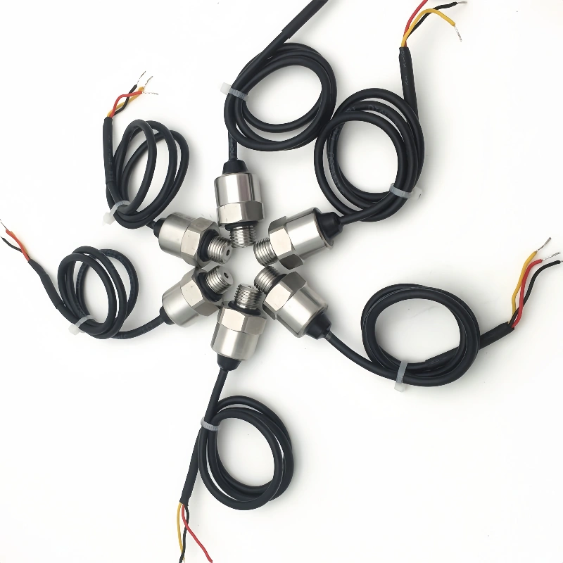
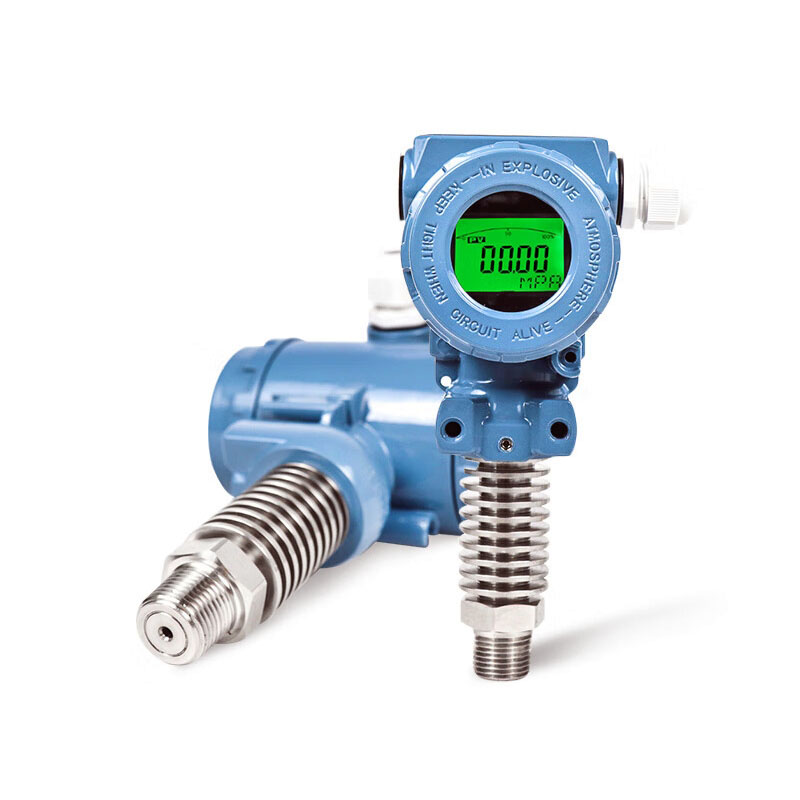
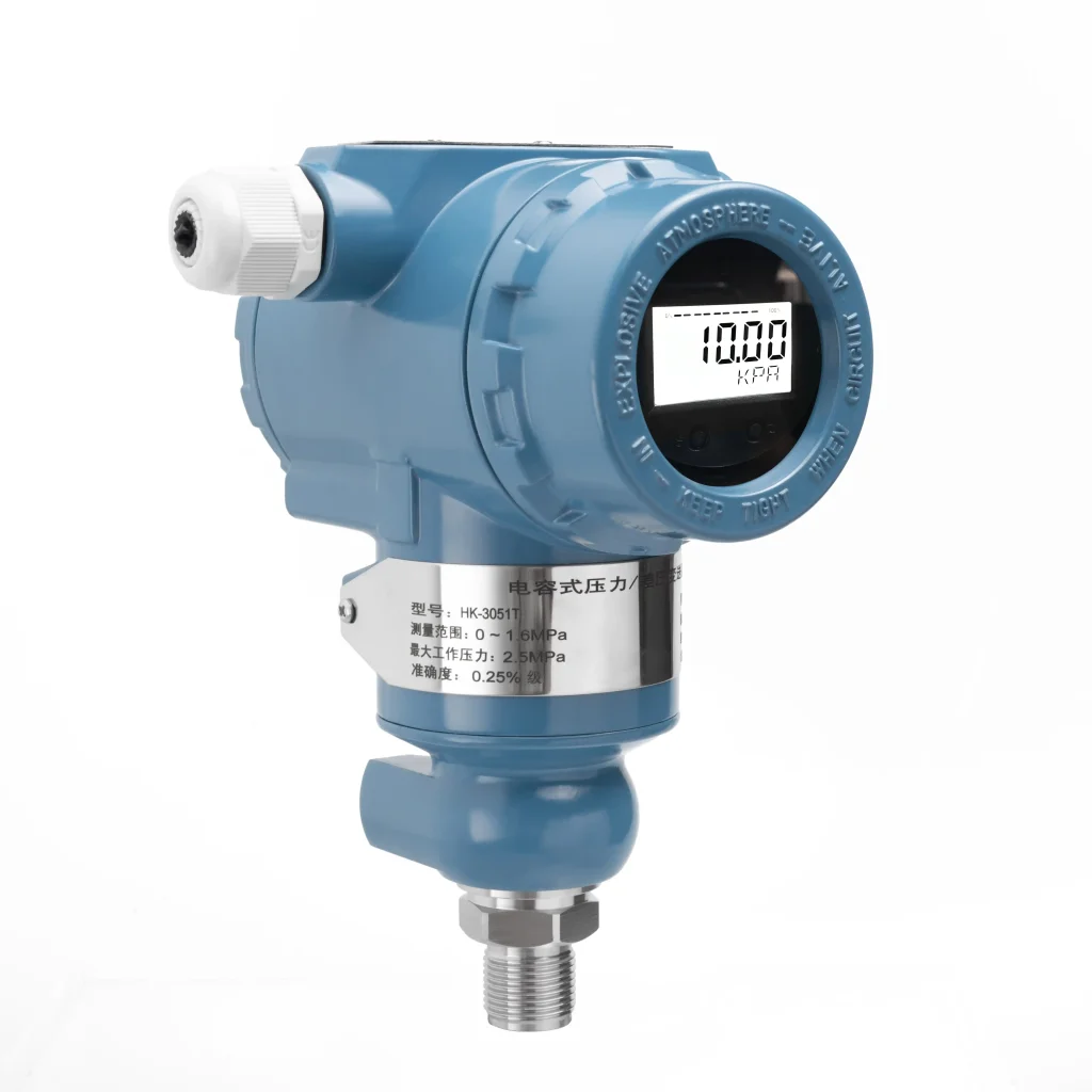
The proper approach is to match the transmitter based on the steam temperature range and the required condensation/heat dissipation configuration: saturated steam can be measured using a standard high-temperature transmitter equipped with a condensation tank, while superheated steam requires extended heat dissipation and, depending on the temperature, upgraded diaphragms and fill fluids.
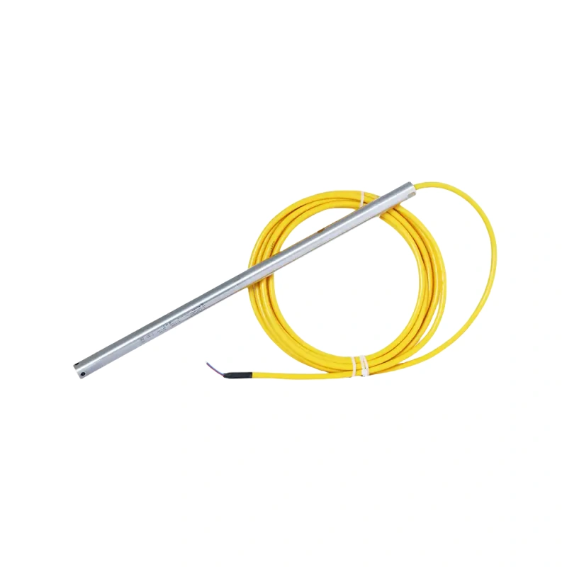
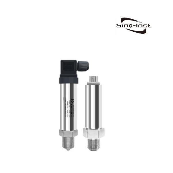
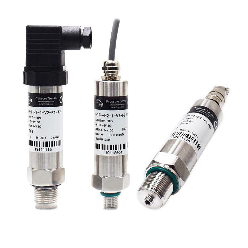
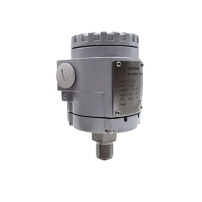
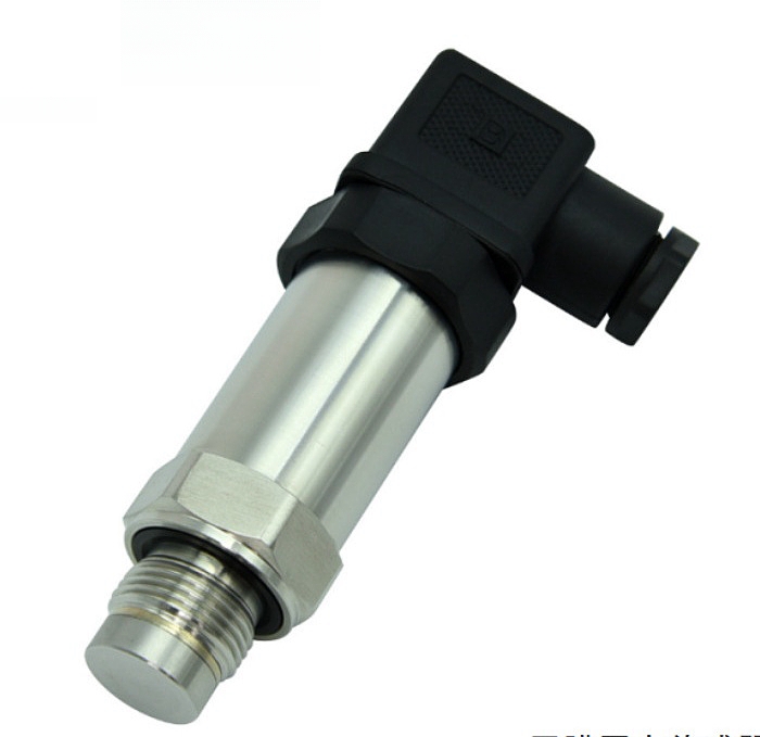
Sino-Inst offers a full range of high-temperature pressure measurement solutions covering 125°C to 1200°C. All products can be customized for range, temperature, process connection threads, and explosion-proof ratings, and come standard with a 4–20 mA output for seamless integration into control systems.
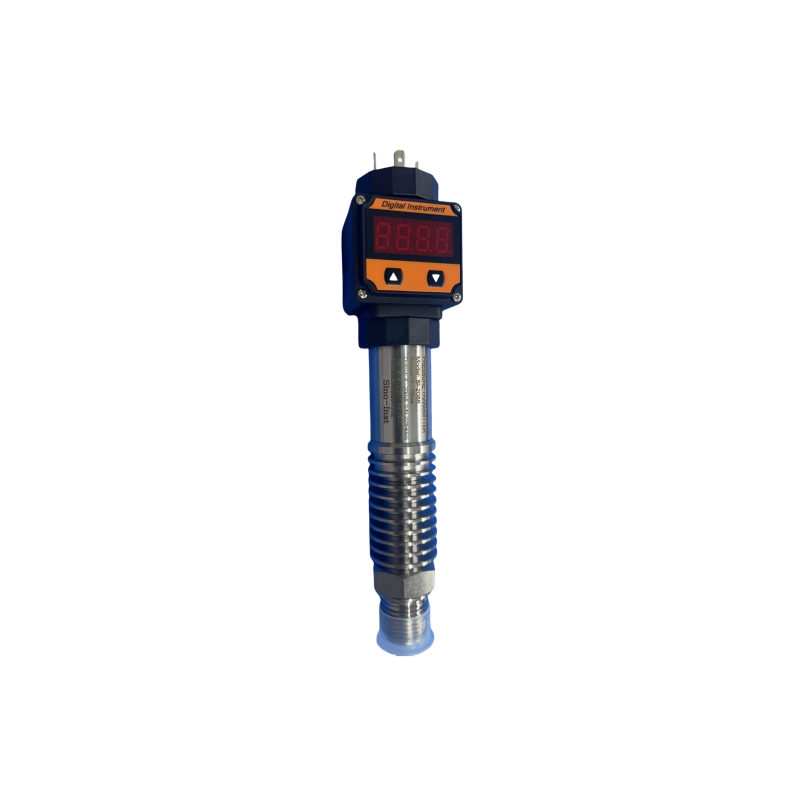
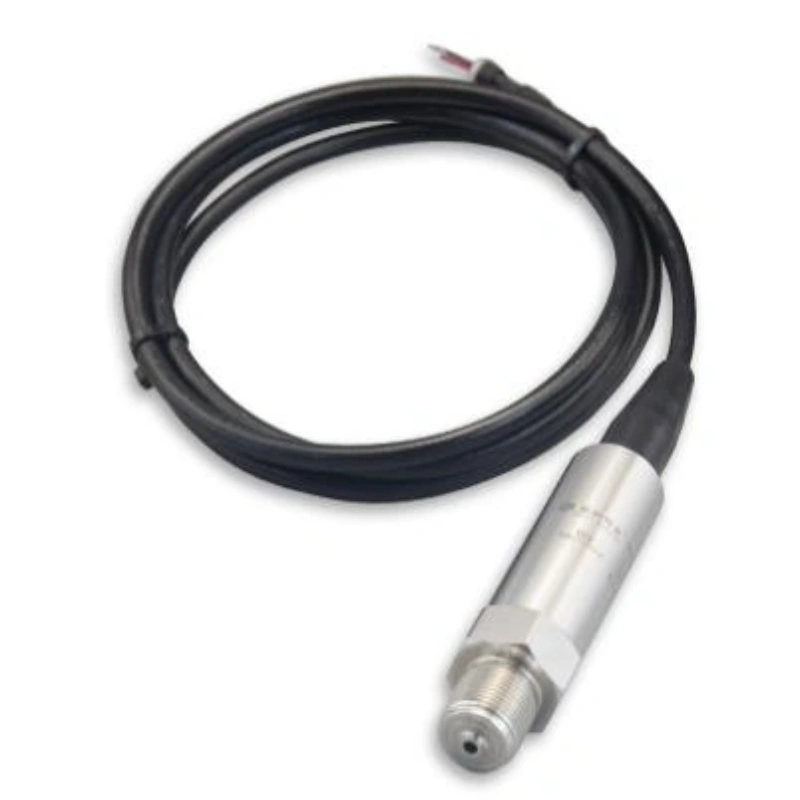
125°C to 500°C saturated/superheated steam: Go with the SI-2088 high-temperature pressure transmitter. It’s got a heat dissipation structure and a condensation chamber—solid bang for your buck.
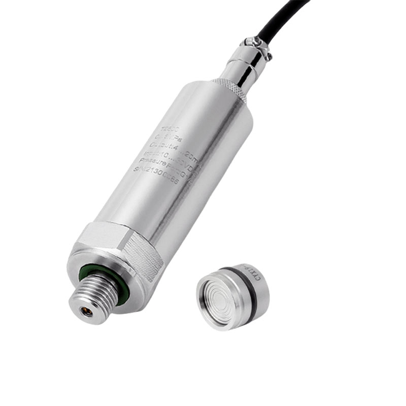
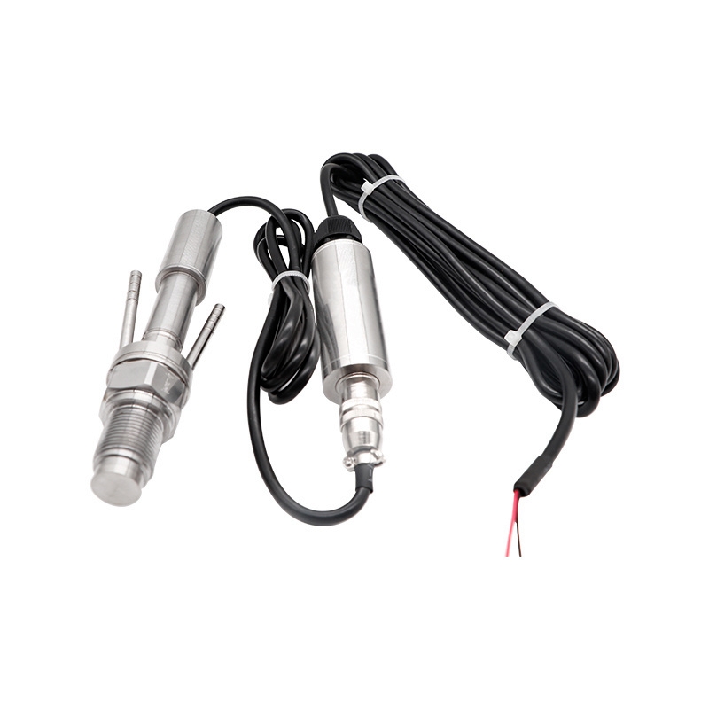
800°C to 1200°C ultra-high-temperature conditions: You’ll want a water-cooled ultra-high-temperature pressure transmitter. It keeps the core components cool with active cooling.
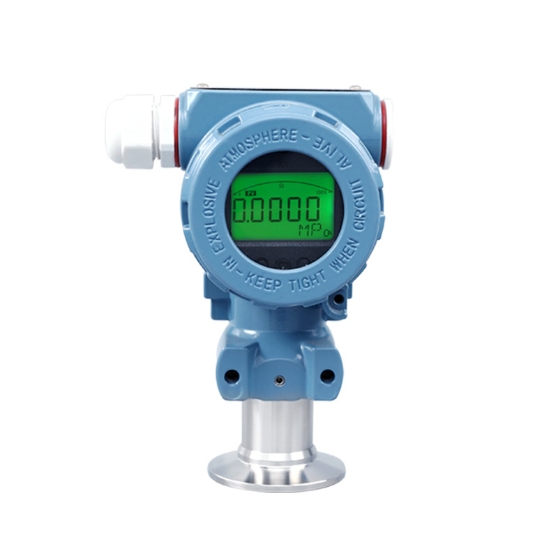
For simultaneous temperature compensation: The SI-706 integrated temperature and pressure transmitter is your best bet. It spits out both temperature and pressure from one unit, which makes wiring a lot simpler when you’re doing saturated steam temperature and pressure correction.
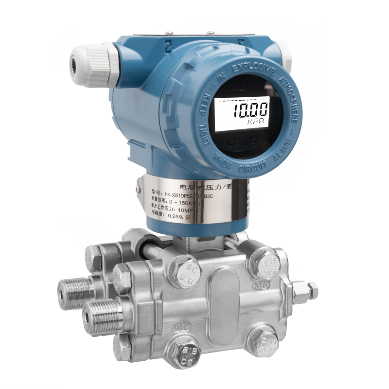
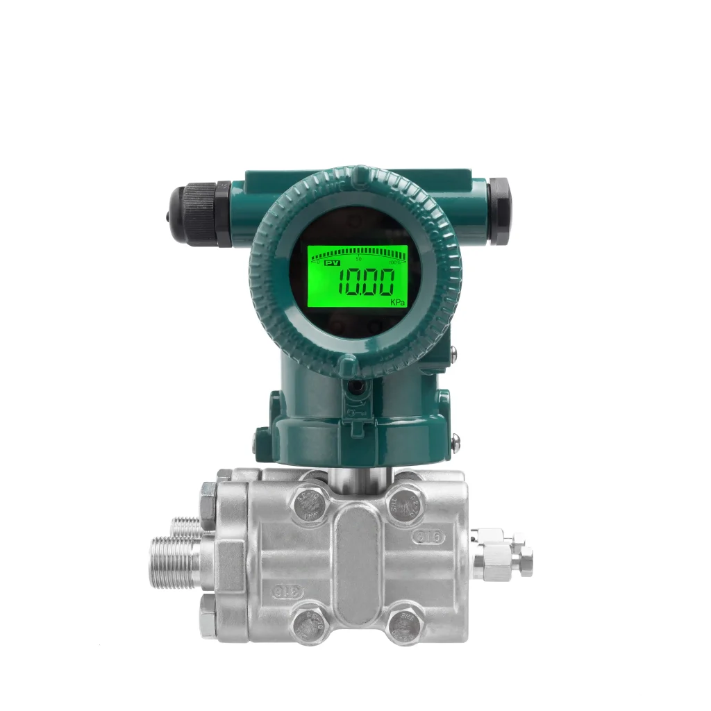
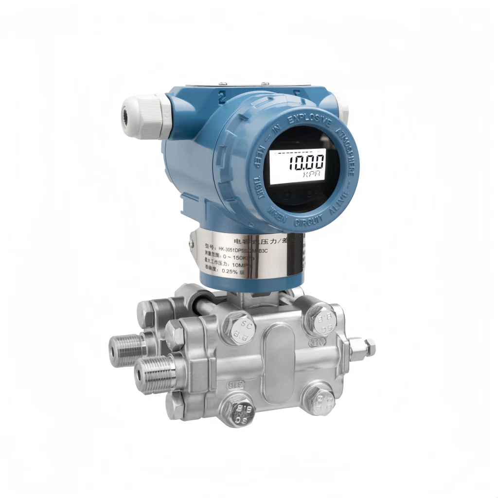
Differential pressure measurement for steam flow: Choose the SMT3151 capacitive differential pressure transmitter, paired with condensation chambers of equal height on both sides to eliminate fixed liquid column errors.
For more models, see the High-Temperature Pressure Transmitter Category Page and the Steam Pressure Sensor Special Feature. For customized selection based on your steam temperature, pressure range, and pipe connections, please contact a Sino-Inst engineer directly.
Sino-Inst possesses mature capabilities for steam measurement applications. In addition to standardized installation and maintenance solutions for steam pressure transmitters, Sino-Inst offers a full range of steam flowmeters, including vortex flowmeters, orifice plate differential pressure flow meters, and mass flow meters.
These are suitable for both saturated and superheated steam conditions and can be integrated with pressure monitoring systems to achieve integrated, precise measurement and control of steam pressure and flow, providing reliable equipment and technical support for the stable operation of production lines and refined energy consumption management.