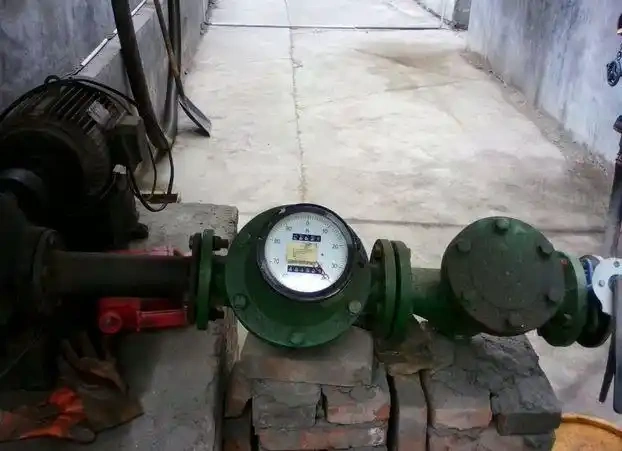
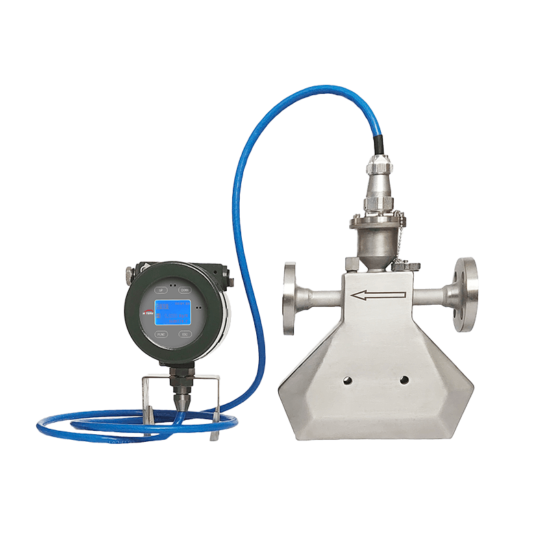
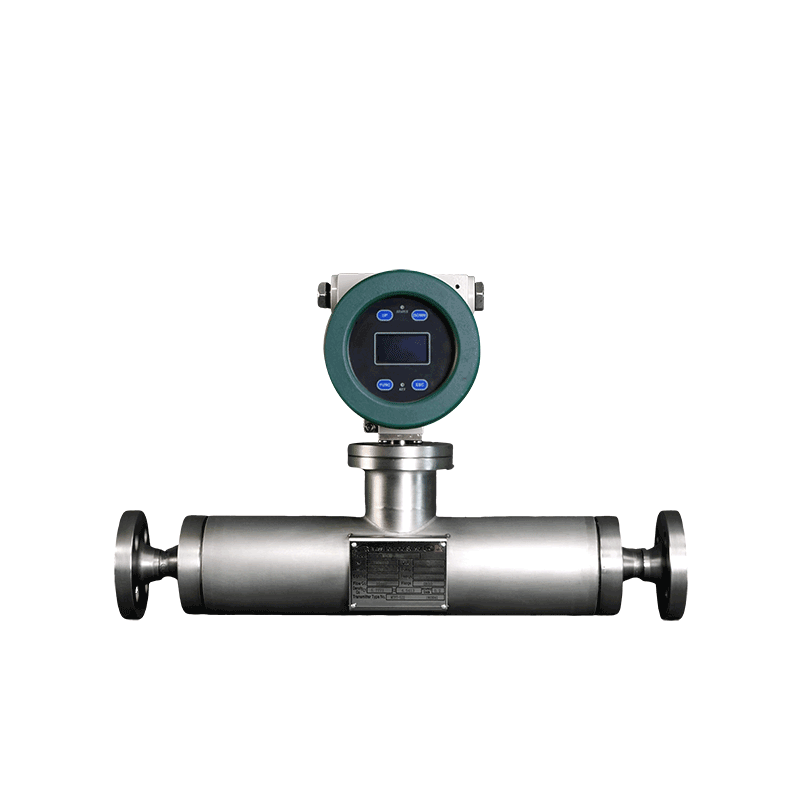
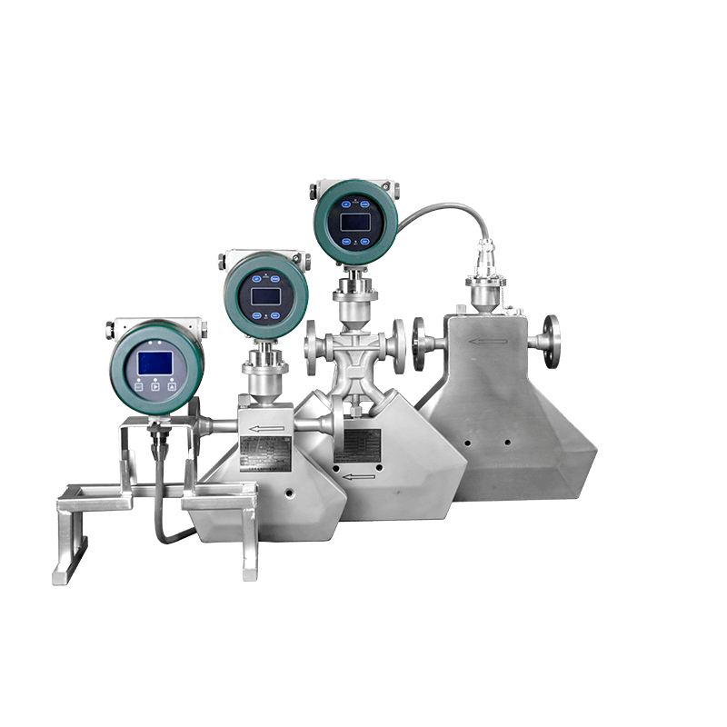
Coriolis mass flow meters (CMFs) utilise the Coriolis effect to provide direct, high-precision measurement of fluid mass flow rate. They can simultaneously measure multiple parameters such as medium density and temperature, and are widely used in high-end industrial sectors including petrochemicals, pharmaceuticals and food processing.
Their measurement performance is closely linked to the adherence to installation standards. Factors such as pipeline stress, vibration interference and fluid flow patterns during the installation of Coriolis mass flow meters directly affect the instrument’s zero-point stability and measurement accuracy. Therefore, a scientifically sound and standardised installation is a key prerequisite for realising the instrument’s metrological advantages and ensuring long-term, stable operation.
Principle of Operation of Coriolis Mass Flow Meters
Coriolis mass flow meters operate on the basis of the Coriolis effect, with their core comprising a measuring tube, a drive unit, a sensor and a signal processing unit. The measuring tube serves both as the fluid passage and as a vibrating element; the drive unit causes it to vibrate at a stable frequency, whilst the sensor detects changes in this vibration to measure the mass flow rate of the fluid.
When the fluid is at rest, the measuring tubes vibrate symmetrically; the vibration phases of the two tubes are in phase with no phase difference, and the system is in equilibrium, making it impossible to measure flow. When the fluid flows, it is subjected to the Coriolis force, which is proportional to the mass flow rate.
When liquid flows through the two tubes in opposite directions, the Coriolis force causes them to bend in opposite directions. This creates a vibration phase difference that is directly related to the flow rate.This vibration phase difference is directly related to the flow rate.
Installation Methods for Coriolis Mass Flow Meters
Horizontal Installation
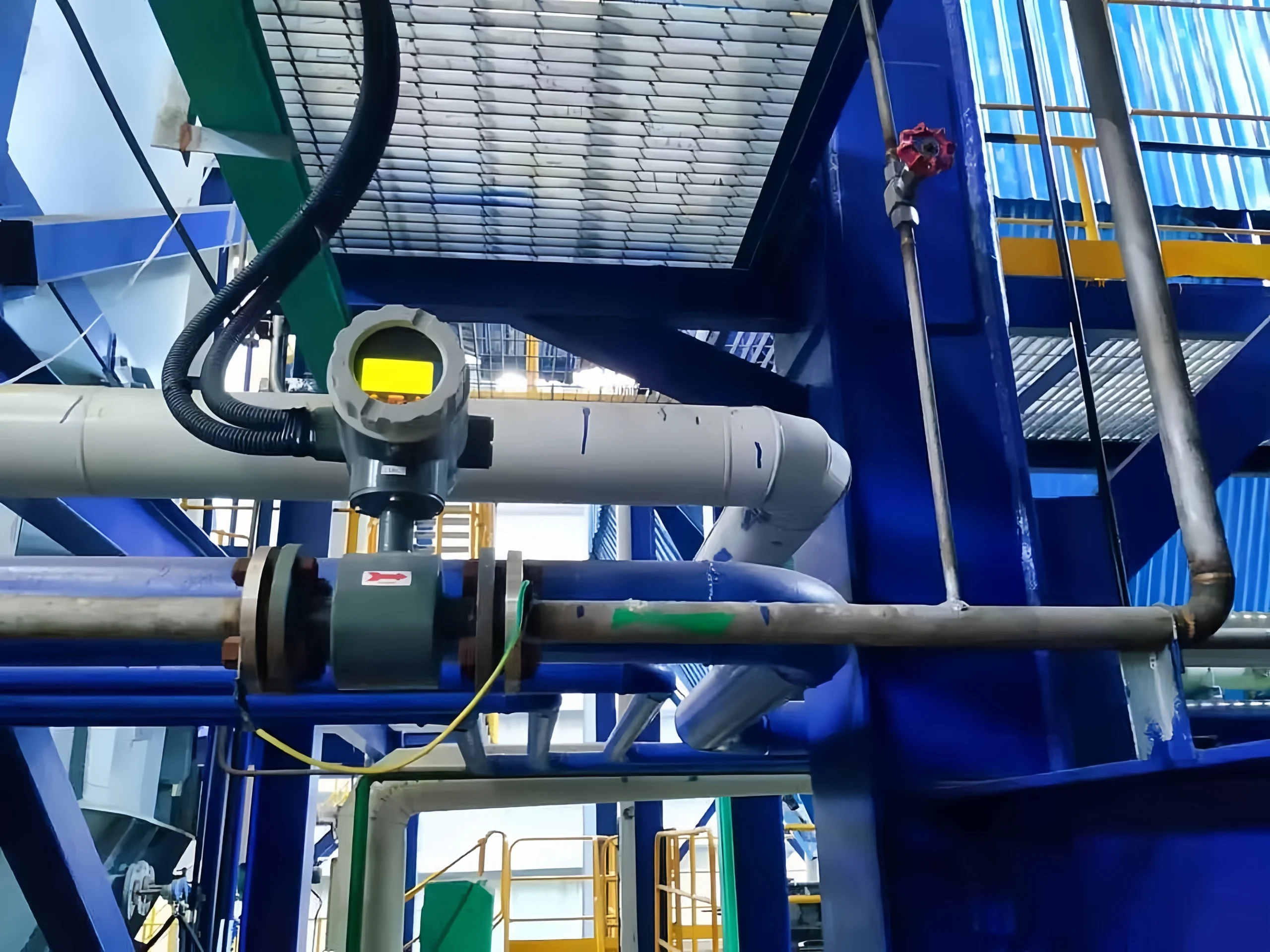
When you’re installing the flow meter horizontally for liquid media, make sure the measuring tube and the transmitter body face downwards and are positioned at the lowest point of the pipeline. This stops air bubbles building up, makes sure the measuring tube is always full and stops the liquid from evaporating, which would mess up the reading.
When installing the flow meter horizontally for gaseous media, the transmitter body should face upwards and be positioned away from the lowest point of the pipeline to prevent condensate from remaining in the measuring tube and causing measurement errors.
When you’re dealing with slurries and media that contain solid particles, make sure you install the instrument body upside down when it’s horizontal. This helps to drain the medium easily and reduces the chance of solid impurities settling and causing blockages at the bottom of the measuring tube.
It should not be put at the highest point of the pipeline when it is installed horizontally. This will keep air spaces from forming, which would lead to a two-phase flow of gas and liquid. Also, make sure the pipeline is properly supported so that the instrument doesn’t hang off the end while it’s being installed. This could make it less stable.
Vertical Installation
Here are some broad recommendations about how to move forward: Installing the measurement tube vertically with a bottom-to-top flow is ideal for liquids and slurries so that gravity may exhaust it. In order for bubbles to naturally rise and leave, this guarantees that the measurement tube is constantly filled. Additionally, this keeps solid particles from settling or becoming stuck.
For gaseous media, the pipeline should be installed vertically to allow the gas to flow downwards. This prevents condensation from building up inside the measuring tube, which can lead to measurement errors caused by liquid accumulation.
Vertical installation is ideal for applications involving muddy or impure media that need to be self-draining. It is particularly well-suited to sanitary applications in the food and pharmaceutical industries, meeting the requirement for complete, residue-free drainage of the pipeline.
Vertical installation also requires sufficient space for inspection and maintenance. The instrument should be secured using pipe brackets to minimise the transmission of pipeline vibration and mechanical stress.
Installation Requirements for Coriolis Mass Flow Meters
1. Coriolis mass flow meters must be installed away from sources of disturbance that could cause pipe vibration, such as pumps on process pipelines. If sensors are used in series on the same pipeline, to prevent mutual interference caused by resonance, the distance between sensors must be at least three times the width of the sensor’s outer dimensions.
2. The installation locati0n must take into account thermal expansion or deformation of the process pipeline caused by temperature changes. Installation must not take place near expansion joints in the process pipeline. If installed in such a locati0n, pipeline expansion may cause transverse stress, resulting in a shift in the sensor’s zero point and affecting measurement accuracy.
3. Additionally, it is crucial to ensure that the installation site is far from sources of industrial electromagnetic interference, such as high-power motors and transformers. Otherwise, the sensor’s measuring tube might vibrate due to interference. This might cause electromagnetic noise to overpower weak transmissions. A distance of at least 5 metres from such interference sources is required.
4. The sensor must be installed at the low end of the pipeline to ensure that the fluid within the pipeline consistently fills the sensor’s measuring tube and maintains a certain backpressure.
Installation Steps for Coriolis Mass Flow Meters
Selecting the Installation Location
When we’re picking where to install things, we’ve got to think about how the medium flows and what the equipment needs to do. Try to keep straight pipe sections, and avoid areas where there might be problems with fluid, like bends, valves and pump bodies.
The straight pipe section’s got to be the right length for the equipment. At the same time, make sure the pipe is at the right angle, with the slope going in the same direction as the medium’s flow.
This makes it easier for the liquid to escape, avoiding the buildup of liquid or air in the pipe that might compromise measurement accuracy or harm the equipment’s sensors. Place the device away from electromagnetic interference and intense vibrations, and make sure there is adequate room for maintenance. Make sure the unit is kept out of direct sunshine and rain, and maintain a temperature between -20°C and 60°C.
Power Supply and Signal Cables
I wanted to inform you that a steady DC or AC power source is necessary for Coriolis mass flowmeters. Voltage fluctuations should be kept between ±10% to prevent any issues brought on by unstable voltage.
Shielded cables should be used for signal lines to avoid electromagnetic interference impacting the measurement signal. Make sure you route the cables away from the power cables, keeping the route as short as possible and avoiding excessive bending.
When you’re hooking up signal lines, make sure you tell the difference between positive and negative terminals and signal terminals, and follow the equipment manual to a T to make sure everything works smoothly with the control system (like PLC, DCS). You’ve got to do an insulation test after wiring to stop short circuits or signal leakage.
Installation of the Flow Meter
Before you install it, have a look at the flow meter to make sure its exterior is undamaged and check that components such as the sensor and converter are intact. Make sure the equipment model matches the pipe specs.
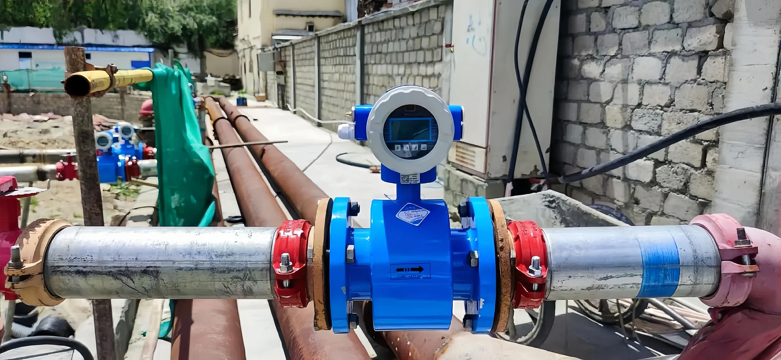
When you’re installing it, make sure you use a flanged connection to get the flow meter housing lined up right with the pipe. Just make sure you use sealing gaskets that are compatible with the medium.
When tightening the flange bolts, apply pressure at an angle and ensure it is consistent throughout. This will help prevent uneven stress, which can result in joint leakage or equipment deformation.
Also, make sure you install the flow meter in line with the direction of the medium flow, ensuring the arrow points in the same direction. Please note that you cannot install the software backwards to prevent damage to the equipment.
Commissioning and Calibration
Once you’ve installed it, just run a no-load commissioning test first. So, connect the power supply and check that all the indicator lights and the display screen are working normally.
Then, just confirm that the signal line communication is working correctly. Subsequently, carry out a load commissioning test by introducing the medium to be measured.
Once the flow has stabilised, calibrate the Coriolis mass flow meter against a standard flow meter or calibration device, adjusting parameters such as zero point and span to ensure measurement error is controlled within the device’s permissible range (typically ±0.1% to ±0.5%).
During commissioning, record all parameters and compile a calibration report to facilitate subsequent traceability and maintenance.
Maintenance and Servicing
To make sure the equipment works properly for a long time, it needs to be serviced regularly. Keep the flowmeter clean by choosing the right cleaning method for the liquid you are using. This will remove any dirt or other things that might be in the sensor and stop it from working properly.
Use a lubricant on the places where the equipment is joined together. This will stop the bolts from rusting and the seals from getting old.
Re-calibrate the equipment every 6–12 months to correct any mistakes in the measurements.
When you are using the equipment, check the connections of the power and signal cables regularly. Also, check that the equipment is working properly and turn it off if something is wrong. This will stop the problem from getting worse.
Installation of Coriolis Mass Flow Meters in Extreme High and Low Temperature Environments
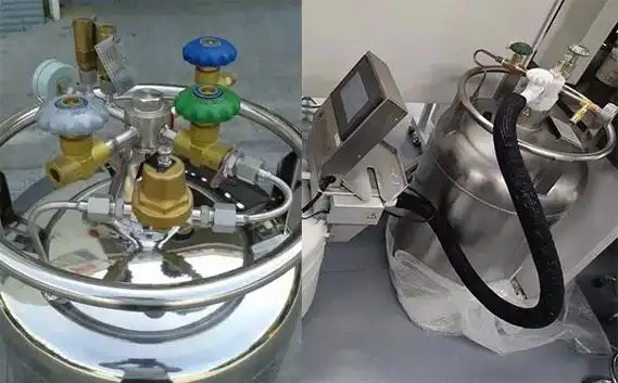
Installation for Low-Temperature Media (e.g. Liquid Nitrogen)
Select sensors and seals made from materials specifically designed for low-temperature applications to prevent brittle fracture and seal failure.
The entire flow meter must be fitted with thermal insulation to prevent external moisture from causing frost or ice formation, which could affect measurement accuracy or damage the instrument.
Install flexible expansion joints in the piping to counteract stresses caused by pipe contraction at low temperatures, thereby preventing the sensor from deforming under tensile or compressive forces.
Just make sure you install it somewhere shady, away from anything too hot or cold. Make sure you get the straight pipe runs right, following the specs, and keep the medium flowing at full speed without any cavitation. This’ll help stop two-phase flow messing up the mass measurement.
Ensure that instrument wiring and transmitters are properly sealed against moisture to prevent circuit faults caused by condensation at low temperatures.
Installation for High-Temperature Media (Heat Transfer Oil, Asphalt-based Substances)
Pick a Coriolis mass flow meter model that can handle high temperatures. Make sure the material can deal with the heat and the temperature range.
The flow meter must be isolated from the high-temperature pipeline by using insulated brackets and an installation method. This will prevent heat transfer to the transmitter and electronic components.
For high-temperature media prone to vaporisation or coking (e.g. bitumen), install the flowmeter with the inlet at the top and the outlet at the bottom to prevent media stagnation, coking and blockage of the measuring tube, thereby ensuring unobstructed flow.
Fit thermal expansion compensators to the piping to absorb thermal expansion stresses from high-temperature pipes and protect the measuring tube from mechanical deformation.
Place the device far from places where explosive or flammable materials might build up. Make sure the electrical wiring satisfies fire safety and heat resistance requirements for high-temperature situations, and provide sufficient protection for the instrument against heat dissipation.
Calibration of Coriolis Mass Flow Meters
Pre-calibration preparation:
Make sure the flow meter’s been installed right, that the straight pipe bits upstream and downstream meet the required specs, and that the unit’s been placed away from any potential sources of vibration or electromagnetic interference.
Make sure you’ve got some high-precision standards ready (with an accuracy one to two grades higher than that of the meter being tested), as well as equipment for getting temperature and pressure data.
Make sure the medium matches the actual operating conditions, and that the pipeline is completely filled with no air bubbles. You can control the temperature fluctuations within plus or minus 1°C; for gaseous media, you can maintain stable pressure to prevent density variations from affecting measurements.
Static Zero Calibration:
Close the upstream and downstream valves to fill the measuring tube with stationary medium. Allow the system to stand for 30–60 minutes to equilibrate temperature and stress.
Enter the transmitter’s zero calibration mode; the instrument will automatically acquire the zero-flow signal from the vibrating tube, calculate and store the zero-point compensation value, thereby eliminating zero-point drift errors. Zero calibration must be repeated after installation, after a change of medium, or following significant temperature fluctuations.
K-factor calibration:
L-Connect the flowmeter under test in series with the standard apparatus, ensuring the correct flow direction of the medium, and slowly increase the pressure to purge air bubbles from the piping. Select 3–5 calibration points (typically 20%, 50%, 80% and 100% of the range) to cover the actual operating range.
Once the flow at each point has stabilised, simultaneously record data from the standard instrument and the meter under test. Repeat the measurement 3–6 times to calculate the indication error and repeatability. If the error exceeds the tolerance, correct the K-factor and recalibrate until the accuracy requirements are met.
Online calibration and verification:
You can compare the meter to a standard flow meter that has been tried under normal working conditions when you do on-site online calibration. You can use either the standard meter method or the flow comparison method.
Note if the results at different places along the pipe are different. If you need to, change the settings on the instrument. Then make sure the numbers you found online are correct. After you’re done adjusting it, you should run a full-range test to make sure it works linearly and the same way every time.
Post-calibration maintenance and record-keeping:
Once you have finished calibrating, save the settings and data and write a report on the calibration medium, the environment and the correction coefficients. Set up a regular calibration schedule and monitor zero-point stability and signal quality daily to quickly spot and fix any drift or faults.
Sino-Inst is a professional provider of flow measurement solutions. We specialise in R&D, production and technical services for flow meters, and we’ve also established a comprehensive range of flow measurement products.
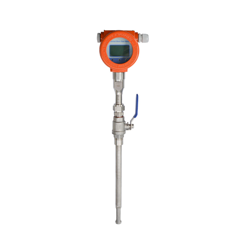
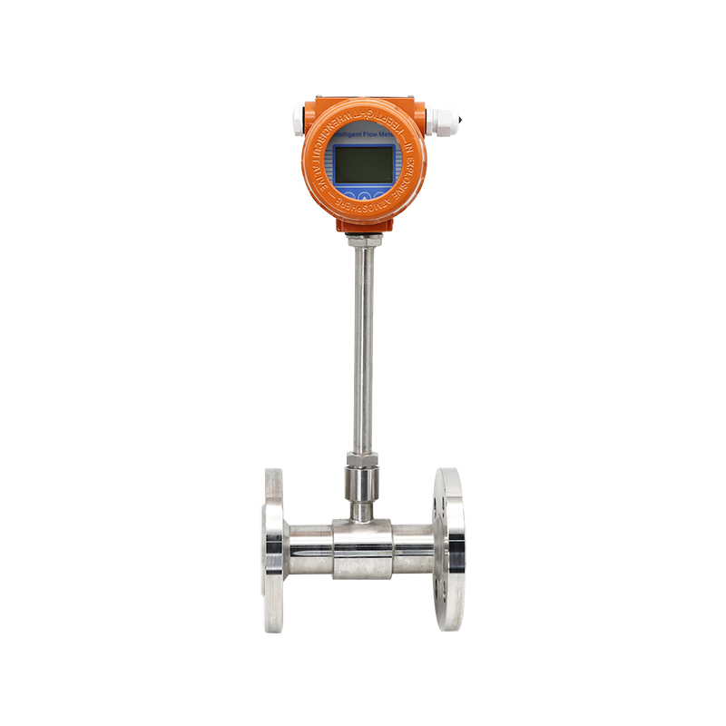
As well as Coriolis mass flow meters, we also offer thermal mass flow meters, turbine flow meters, vortex flowmeters and electromagnetic flowmeters. This means we can meet the measurement needs for lots of different operating conditions and media across multiple industries, including petrochemicals, pharmaceuticals, food processing, new energy and water treatment.