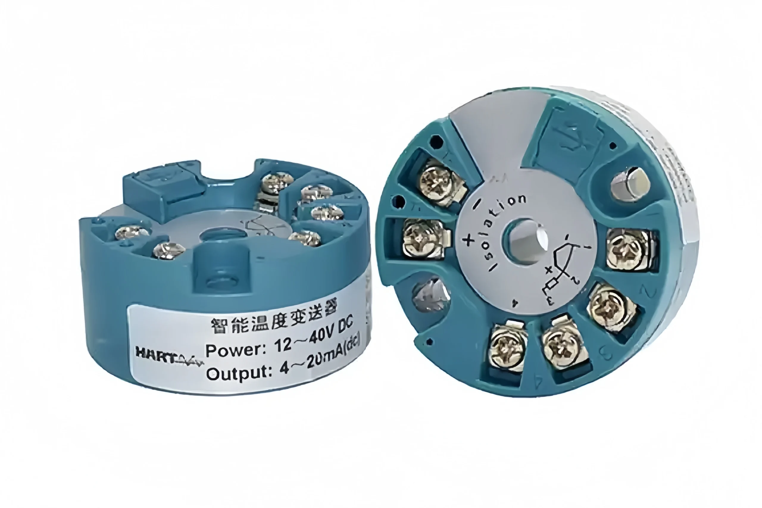
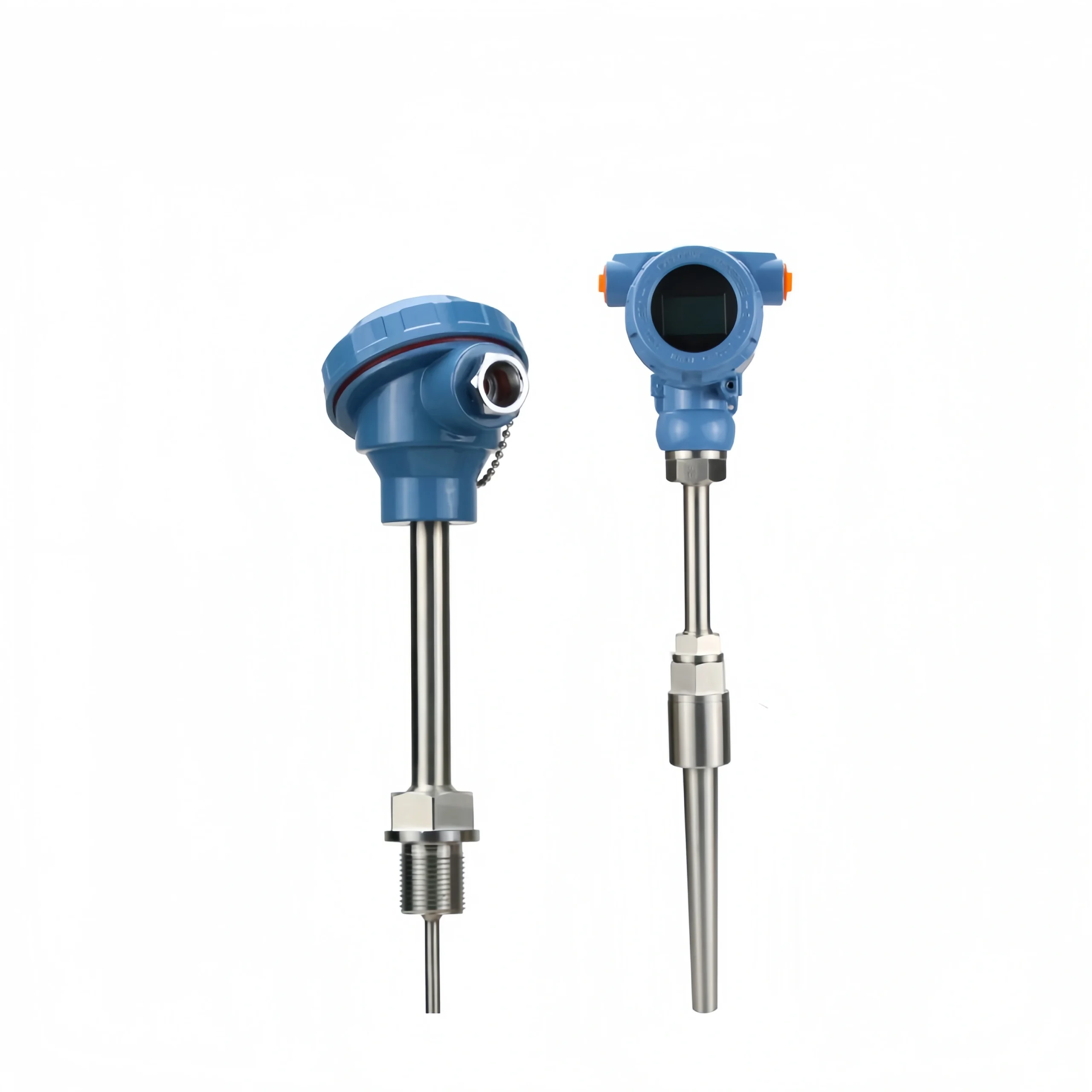
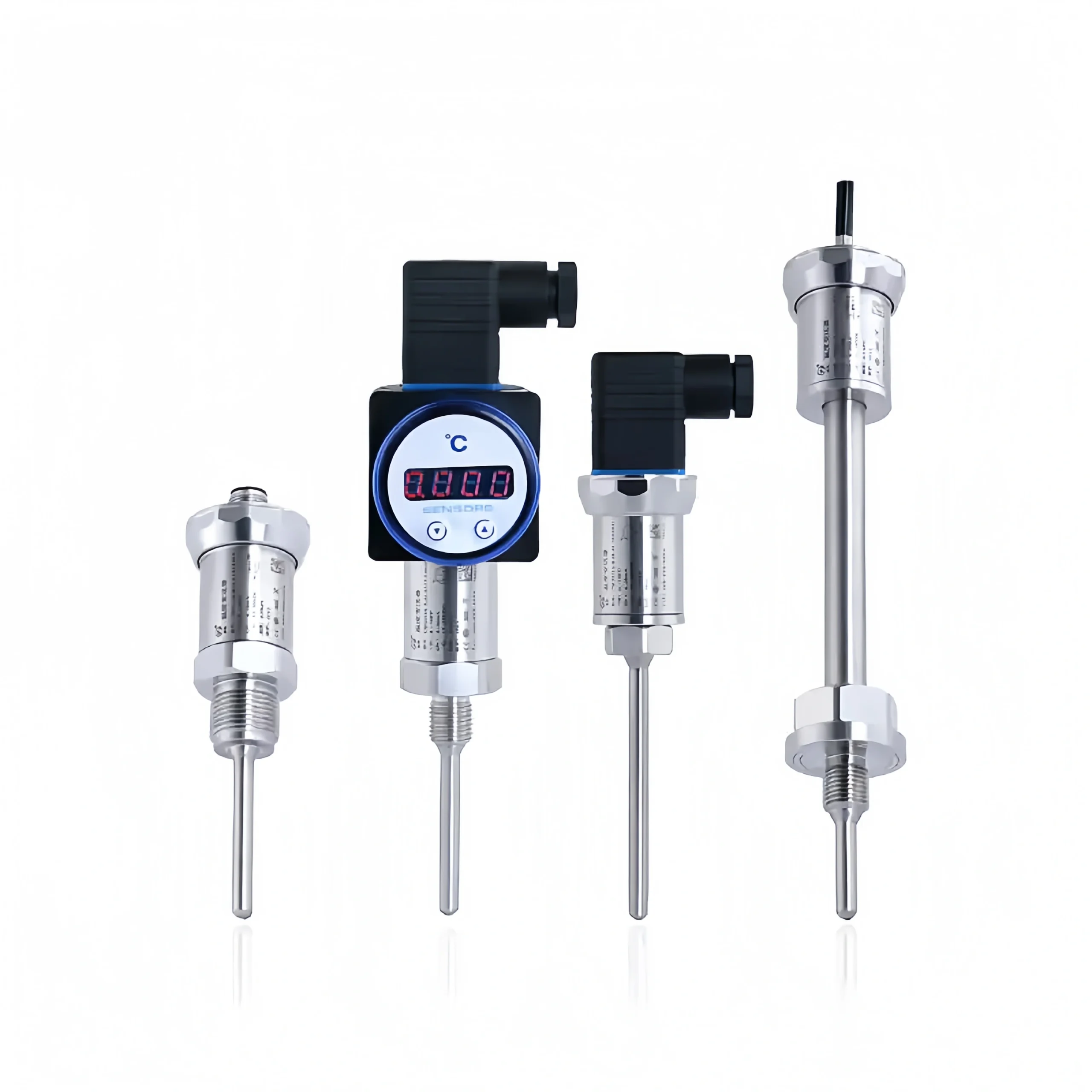
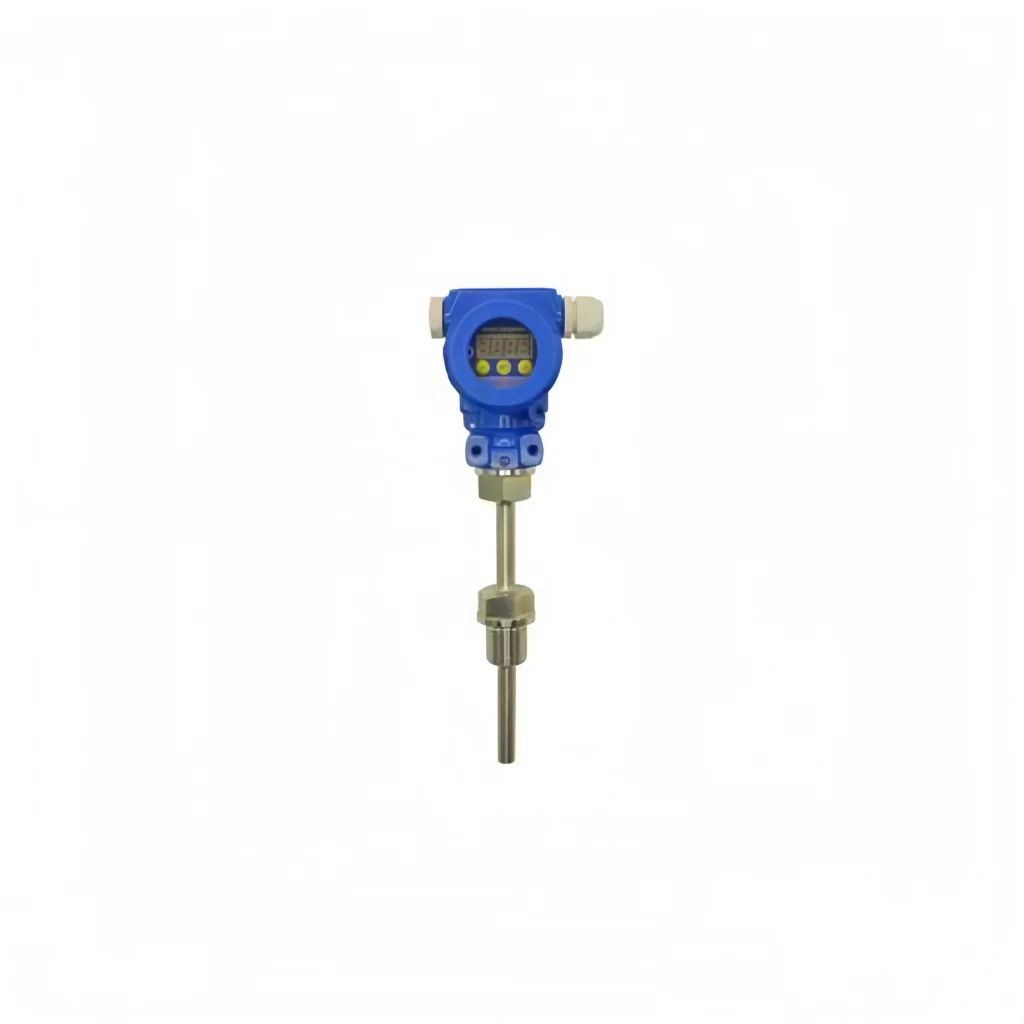
In industrial automation measurement and control systems, temperature transmitters are essential components that connect temperature sensors to back-end control systems. They play a vital role in converting and amplifying temperature signals and transmitting them reliably. The accuracy of temperature measurements and the reliability of the system are directly affected by how they are installed.
Scientific and standardised installation is essential for avoiding interference and ensuring the long-term, stable operation of the equipment; it also forms the basis for realising their value in temperature measurement and control across various industrial sectors.
Pre-installation Preparation
1. Check that the temperature transmitter is suitable for the operating conditions by confirming that the model, range, accuracy, power supply and wiring configuration are appropriate. Also, check that the unit and accessories are in good condition.
2. The installation tools and consumables must be prepared in advance, including wrenches, sealing gaskets and shielded cables.
3. Take a look at where the installation is going to be and ensure that it is in an area that will not be affected by factors such as vibration, electromagnetic interference, high temperatures or corrosion. Also, ensure that the measurement point is easily accessible for maintenance purposes.
4. When it comes to explosion-proof transmitters, make sure that the explosion-proof rating is correct, and that all components are compliant and in good condition.
5. Make sure you take the right safety steps. For example, check that the pipes and equipment are not under pressure, have been cooled down, or have been switched off. Also, make sure you get a work permit if you need one.
6. Inspect the temperature measurement protection sleeve to ensure there are no blockages or leaks, and that the connection surfaces are intact.
7. Plan the wiring layout, distinguishing between power, signal and earth wires, and use shielded cables to minimise interference.
Selecting the Correct Installation Location
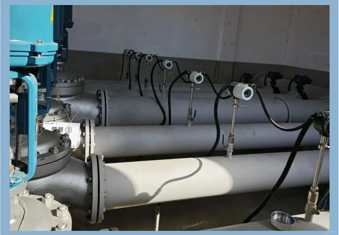
1. Try to use straight pipe sections wherever you can, especially in areas where the flow of the medium is stable and the temperature distribution is even. Try not to put them near valves, bends, tees or reducers, as these can mess up the reading.
2. The installation locati0n must ensure that the temperature-sensing element is fully immersed in the medium being measured. The sensing tip of the thermocouple or resistance temperature detector must be situated in the centre of the pipe, avoiding contact solely with the pipe wall or dead zones in the flow.
Additionally, select an appropriate insertion depth based on the pipe diameter to ensure an effective sensing length.
3. Avoid areas prone to strong vibrations or electromagnetic interference. Keep the device away from high-power motors, variable-frequency drives and high-voltage cables, as well as similar equipment.
This prevents interference from causing temperature signal drift or measurement distortion, whilst also minimising damage to the transmitter’s structure and wiring caused by vibration.
4. Keep the transmitter away from areas with high localised temperatures, severe corrosion and flammable or explosive substances. Just make sure the transmitter housing doesn’t come into contact with high temperatures from the outer pipe wall, as this could affect the transmitter’s service life and explosion-proof safety.
This is because there might be corrosive media or leaking gases. If necessary, install protective sleeves or thermal insulation.
5. Select a locati0n that facilitates installation, wiring, future maintenance and calibration. Ensure that sufficient working space is provided. Avoid installing in confined, elevated or hard-to-reach areas, bearing in mind the requirements for installing and dismantling pipe insulation.
6. For horizontal pipes, installation on the side or top is preferable to prevent condensation or impurities from building up inside the protective sleeve, which could affect the pipe’s response time. For vertical pipes, choose the right height based on the flow direction to prevent bubbles or sediment from forming around the temperature sensing element.
7. If you’re dealing with pipes that are high temperature or high pressure, make sure you check how well they can handle the pressure and how they’re sealed.
Make sure you pick the right flanges, threaded connections and sealing gaskets to make sure the connection is strong enough and the sealing works well, without putting the pipeline’s overall safety at risk.
Installation Procedure
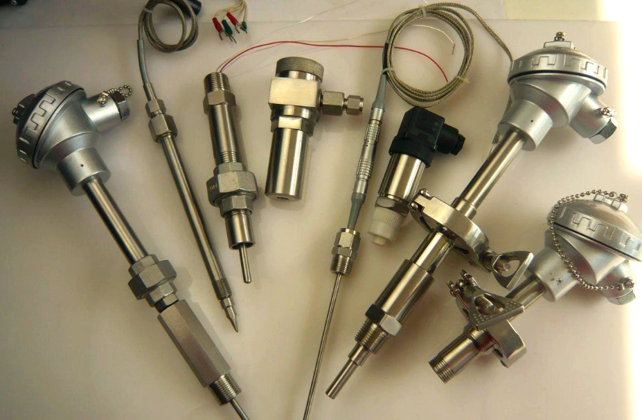
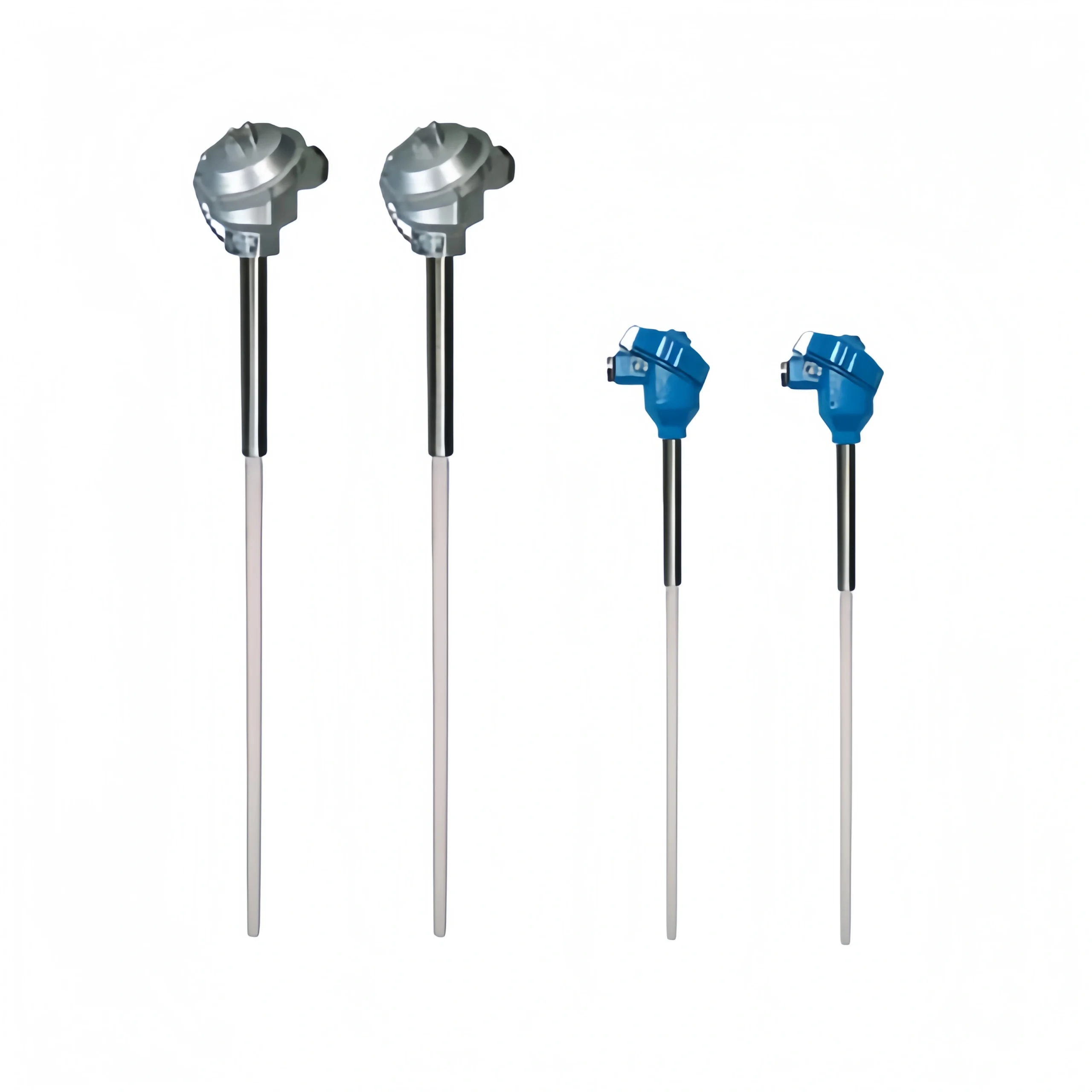
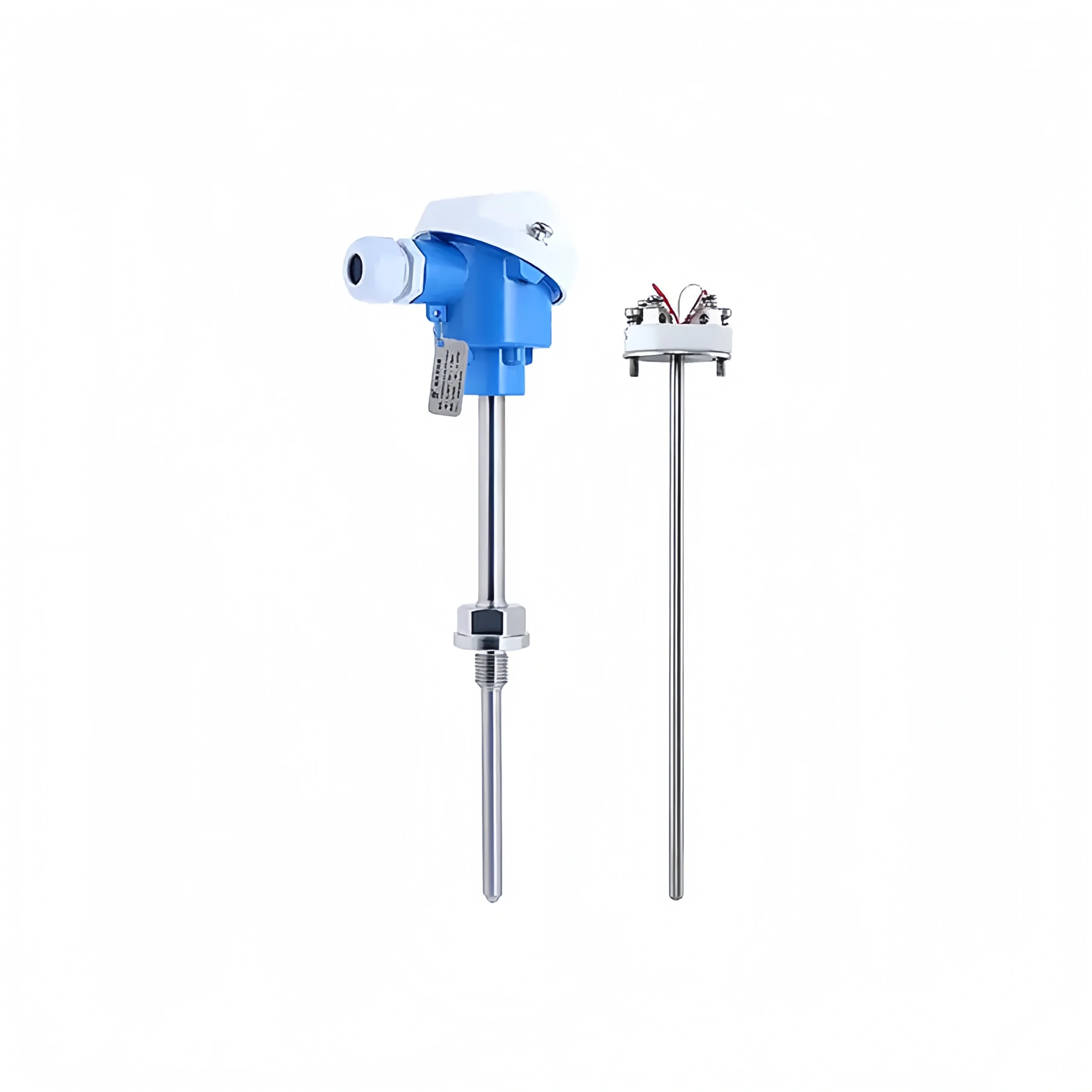
Sensor Installation
The sensor that measures core temperature is part of the temperature transmitter, and it needs to be installed in the right place on the pipeline. Choose the right connection method based on the type of pipeline interface, and make sure you’ve got enough protection to keep everything safe, according to how the pipeline is used.
This will make sure the installation is secure, the temperature is measured accurately, and it works with the pipeline’s operational requirements.
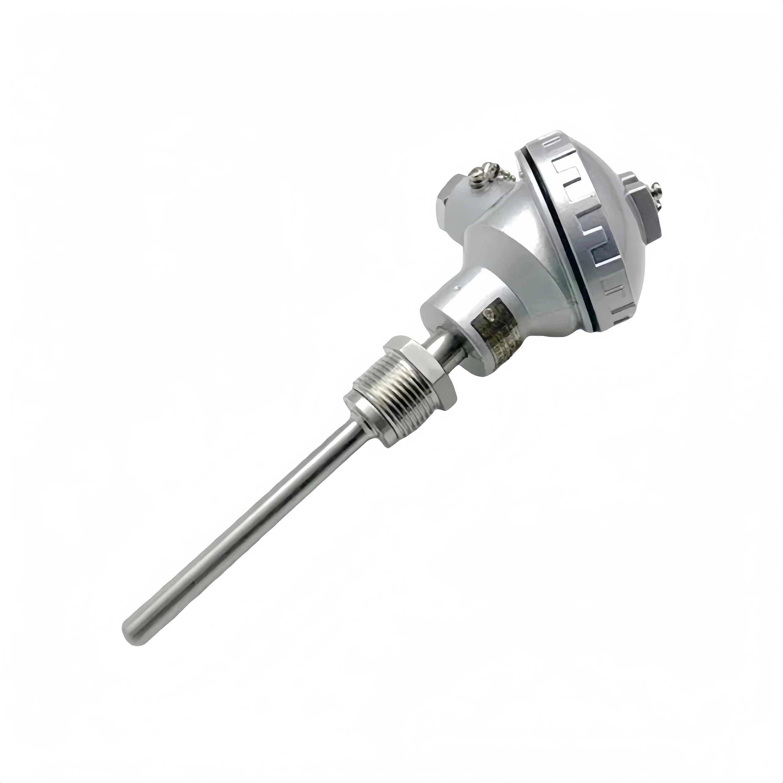
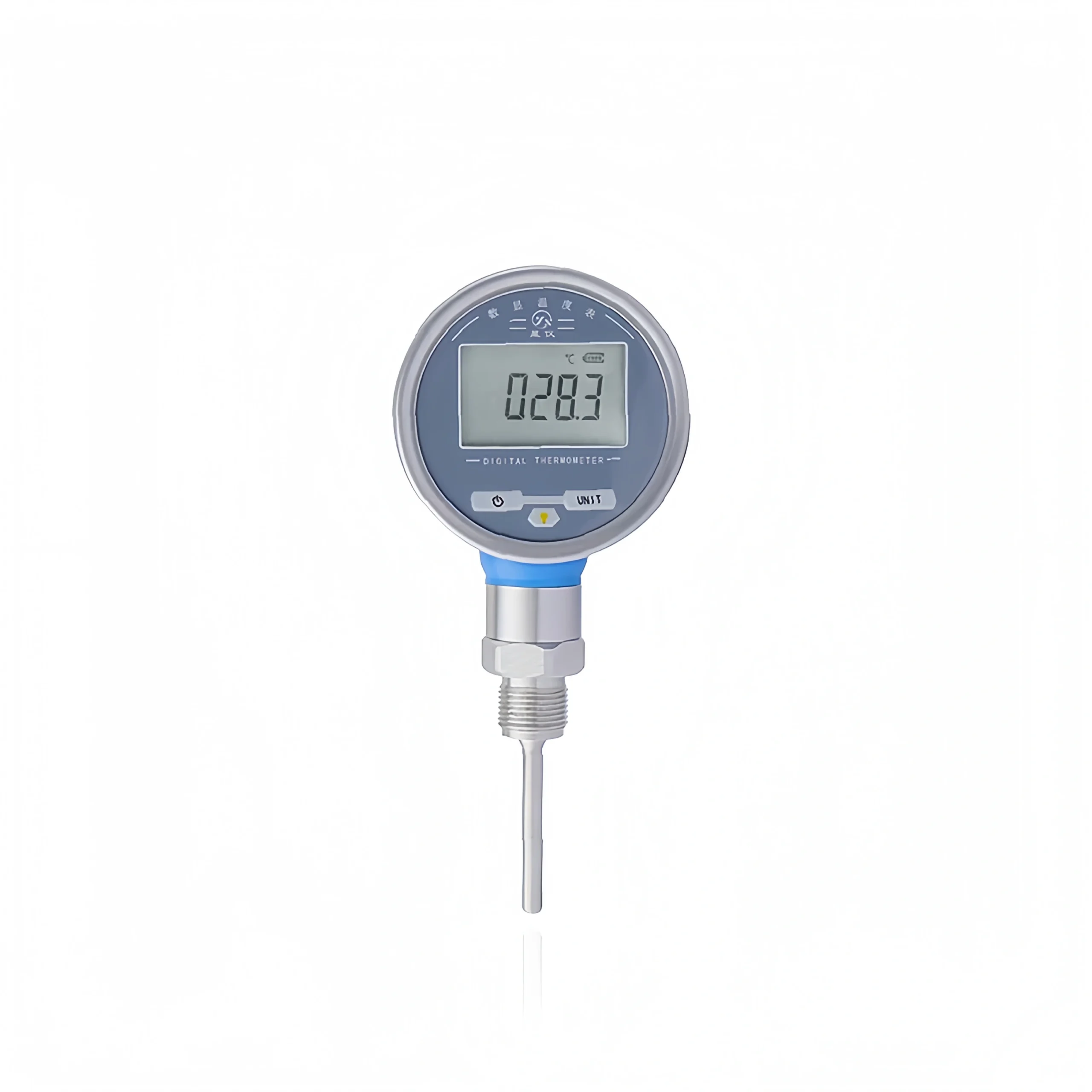
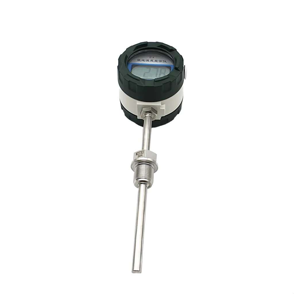
Threaded Connection
First, drill a hole in the correct place on the pipeline and weld on a threaded base that meets the correct specifications. Ensure that the base is securely welded to the pipeline with no leaks. Once the base has cooled and set, apply an even layer of sealant to the threads to improve the seal.
Finally, the sensor should be fitted into the threaded base and tightened using a spanner. However, please exercise caution to avoid over-tightening, as this could cause damage to the threads, sensor or pipeline connection.
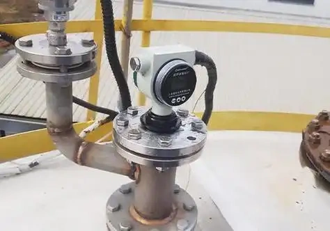
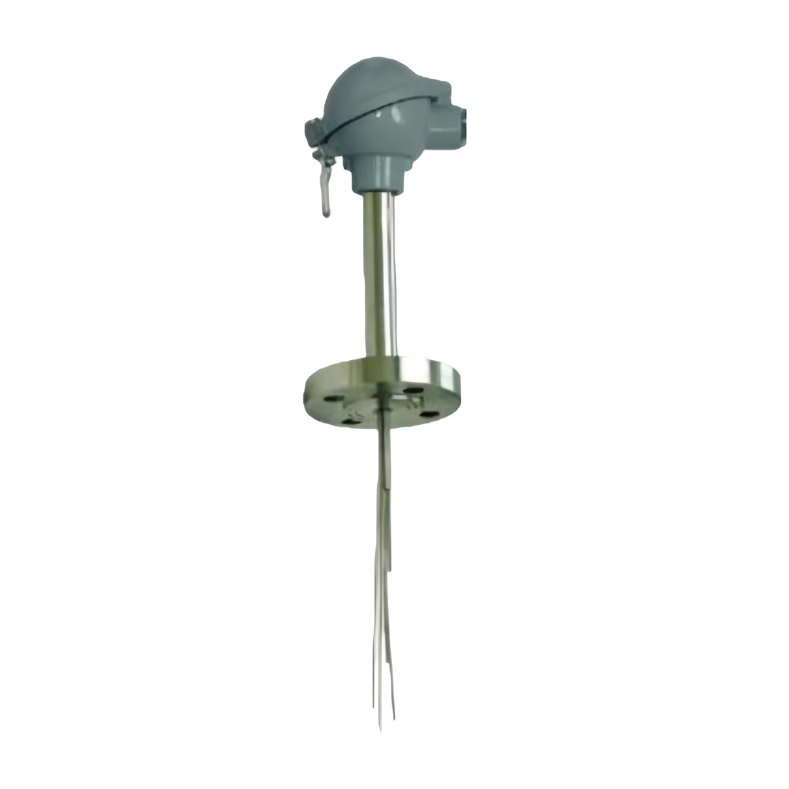
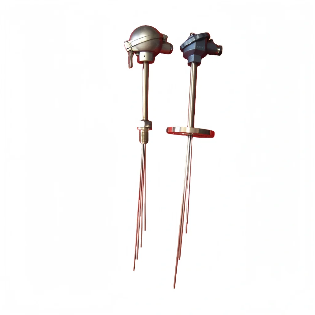
Flange Connection
When it comes to flanged pipe connections, make sure you pick a flange that’s a perfect fit for the pipe flange specs. Fit a suitable sealing gasket to the flange contact surface, ensuring it is tightly fitted and undamaged. Then, using bolts, tighten the flange equally on both sides to make sure there are no leaks where it connects to the pipe.
At the same time, adjust the sensor position so that the temperature-sensing part is pointing at a steady flow area of the liquid inside the pipe. This will make sure that the measurement is accurate.
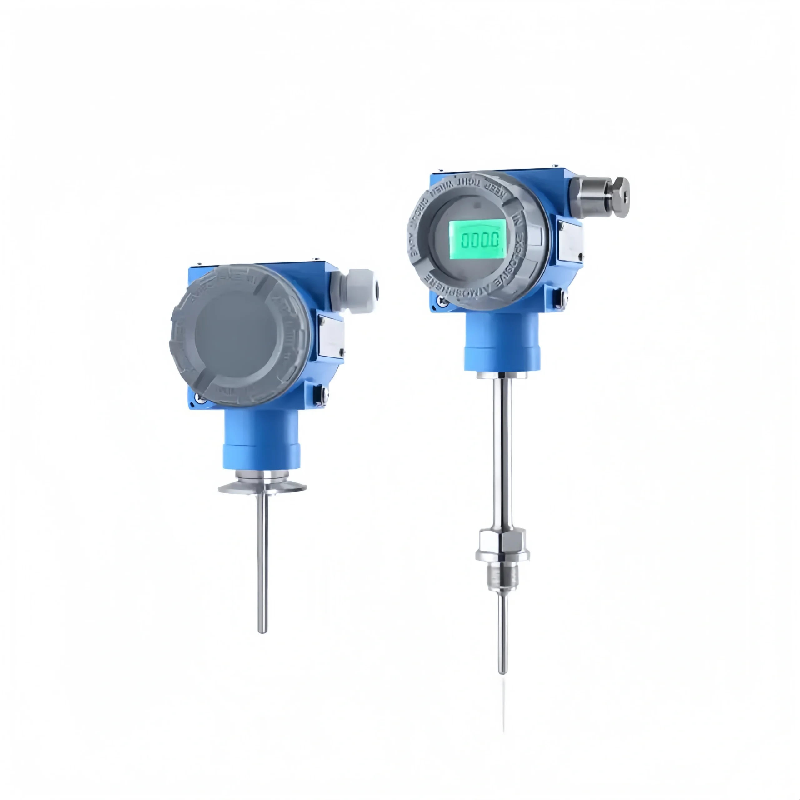
Installation in Harsh Environments
If the pipeline contains corrosive media or operates under high-pressure conditions, the sensor must be installed on the pipeline using a dedicated protective sleeve. During installation, fill the space between the sensor and the protective sleeve with thermal grease; this effectively improves the temperature response speed whilst preventing the sensor from being damaged by the corrosive media or high pressure within the pipeline, ensuring the long-term stable operation of the transmitter under pipeline conditions.
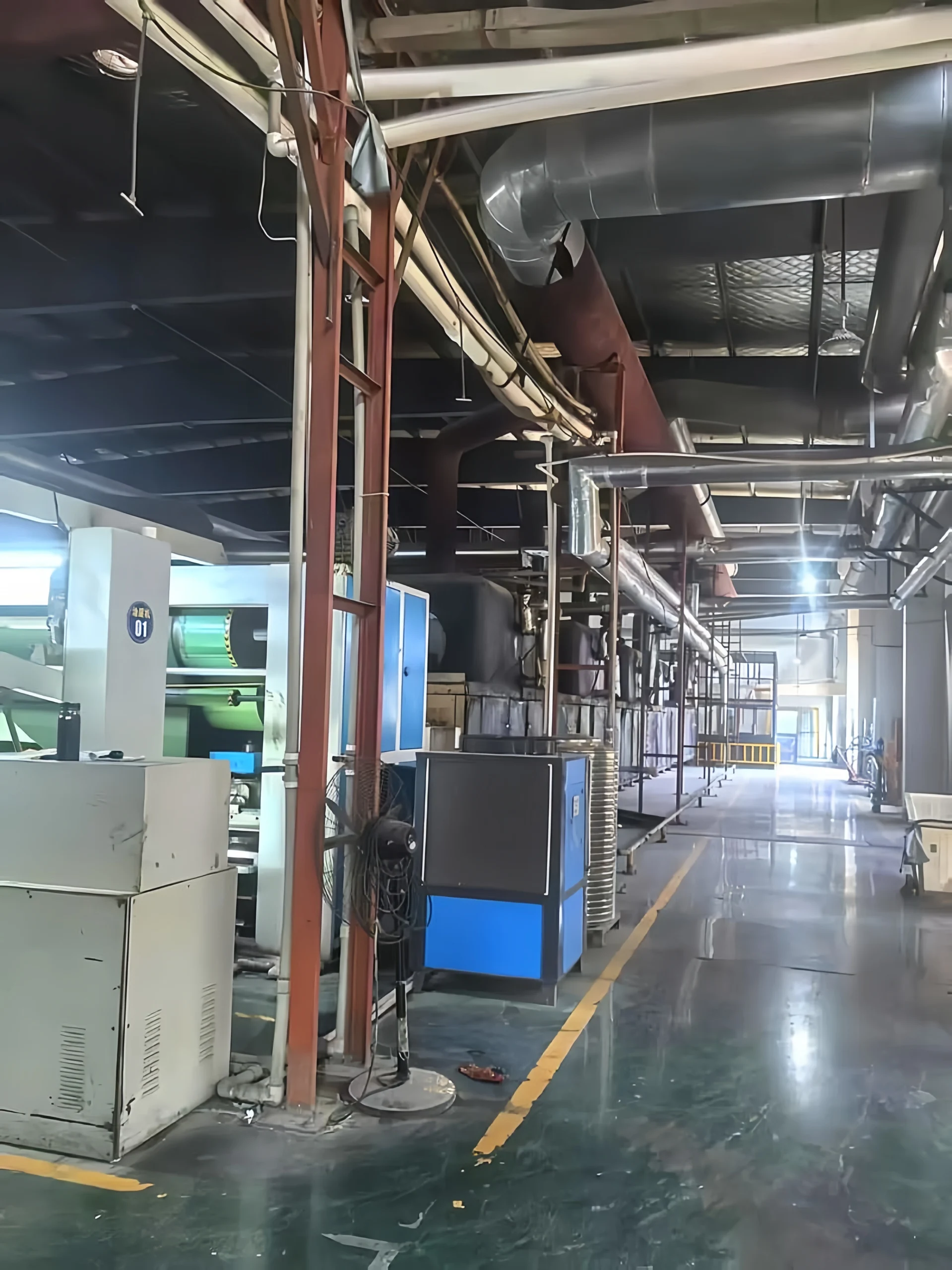
Transmitter Housing Installation
The installation of the transmitter housing must take into account the on-site layout of the pipeline and the operating environment. Select an appropriate installation method, prioritising placement close to the sensor on the pipeline whilst keeping it away from heat sources, damp areas and sources of interference, to ensure normal operation of the equipment and stable signal transmission.
Wall-Mounted Installation
Select a wall surface or the interior of a control cabinet near the pipeline that is dry, well-ventilated, and away from heat sources and damp areas. Secure the transmitter body firmly with screws.
During installation, ensure the transmitter is positioned horizontally or vertically to prevent tilting from affecting stability, whilst minimising the length of the lead wires to the sensor on the pipeline.
On-site Installation
If direct installation at the pipeline site is required, a waterproof transmitter must be selected. Install it near the sensor junction box on the pipeline, minimising the length of the lead wires to the sensor to reduce signal interference.
Additionally, ensure the transmitter is properly protected against water and dust to adapt to the complex on-site conditions, thereby ensuring stable and coordinated operation with the pipeline sensor.
Wiring
1. Before you start, make sure you disconnect the 24 VDC power supply at the site. Just check whether the transmitter is two-wire or four-wire, and whether the sensor is a thermocouple or a resistance temperature detector (RTD).
Confirm the terminal markings on the equipment and use shielded twisted-pair cable; thermocouples must be used with compensation leads of the corresponding calibration scale.
2. Two-wire transmitters use a common line for both power supply and signal transmission. Connect the positive terminal of the 24V supply to the positive terminal of the transmitter, the negative terminal of the transmitter to the positive terminal of the control system’s analogue input, and the negative terminal of the control system’s analogue input to the negative terminal of the 24V supply;
When wiring the sensor, connect the positive and negative terminals of the thermocouple to the corresponding terminals on the transmitter. For a two-wire Pt100, connect directly; for a three-wire Pt100, connect the excitation positive, sensing, and excitation negative terminals respectively.
3. For four-wire transmitters, the power supply and signal lines are separated. The 24V positive and negative terminals are connected to the transmitter’s power supply terminals respectively, whilst the transmitter’s signal positive and negative terminals are connected to the corresponding analogue input terminals on the control system.
The sensor input wiring method is the same as for two-wire systems.
4. The cable shielding needs to be earthed at one point, usually at the control room or instrument cabinet side. It can’t be earthed at both ends at the same time. If you’ve got equipment with a dedicated earth terminal, you need to connect it to the on-site instrument earth busbar.
5. Once you have finished the wiring, check the polarity of the lines, the wire numbers and the terminal connections. Ensure that everything is connected properly and that there are no short circuits. Finally, check that the circuit is working by measuring the continuity.
Once you’ve switched it on, just check that the 4–20 mA output is working normally with the temperature. If it’s not, then have a look at the sensor configuration, wiring or broken wires.
Calibration and Commissioning
Pre-commissioning Preparation
Make sure the wiring is correct, the power supply is stable, and the sensor is properly installed. Have a standard temperature source and a multimeter or handheld programmer ready. Ensure that the transmitter’s range and sensor type match the on-site process requirements.
Zero and Span Calibration
Use the standard temperature source to apply the lower and upper limit temperatures of the range, respectively, and calibrate the transmitter output to 4 mA and 20 mA in turn. Then just tweak the settings a few times to get rid of any common influences between zero and span, and make sure the error stays within the acceptable range.
Multi-point Linearity Calibration
Once you’ve finished calibrating, pick a couple of temperature points in the middle of the range to check, and compare the standard temperature with the output current signal. If the linear deviation is significant, make corrections using the handheld programmer or panel buttons to make sure you get accurate measurements across the full range.
On-site Operating Conditions Commissioning
Reconnect the actual temperature measurement circuit and observe whether the real-time temperature and output signal are stable. Check for issues such as interference or poor heat transfer. Consider the impact of the installation locati0n. Optimise the installation and earthing to ensure reliable measurements under operating conditions.
System Interlock Commissioning
Connect the 4–20mA signal to the DCS/PLC/display instrument and verify that the values on the host and slave systems match. Test whether functions such as alarms and interlocks are operating normally, and confirm that the signal shows no drift or sudden changes.
FAQ
Where is the most suitable locati0n to install a temperature transmitter on a pipe?
When installing a temperature transmitter on a pipe, a straight pipe section should be prioritised; a horizontal straight section or a section where the medium flows vertically upwards is preferable. Bends, tees, valves, reducers and flares should be avoided wherever possible.
These areas can be prone to eddy currents, uneven flow velocity or dead zones, which can lead to variations, delays or distortions in temperature measurements. When you’re installing it in horizontal pipes, it’s best to insert the temperature probe at an angle, facing the direction of flow, or perpendicular to the centreline of the pipe. We don’t recommend installing it in the direction of flow, as the probe might get pushed out of place by the flow and the measurement response will be way delayed.
What is the required insertion depth for a temperature probe?
The most important thing to remember when it comes to the insertion depth of a temperature probe is that the sensing element has to be fully immersed in the medium. When you’re doing it, the probe should be between one-third and two-thirds of the way in, so that the tip is as close as possible to the centre of the pipe, where the temperature is most even and shows what it’s really like.
For small-diameter pipes, if the insertion depth isn’t enough when you insert it vertically, you can try inserting it at a 45° angle or installing it facing the flow direction at a pipe elbow to get enough effective insertion depth. When you’re installing a protective sleeve, make sure the probe touches the bottom of the sleeve completely. This helps to avoid giving the wrong temperature reading because the probe is hanging.
Anything you need to know when installing this on high-temperature pipelines?
When installing temperature transmitters on high-temperature pipelines, first select a suitable high-temperature protective sleeve and transmitter body based on the medium temperature to avoid component damage caused by operating above the temperature limit.
When the medium temperature is excessively high, heat sinks or extension rods may be installed between the sleeve and the transmitter to reduce the temperature conducted to the transmitter head and protect the internal circuitry. Make sure you install this somewhere that isn’t too hot, and shield the transmitter head from direct sunlight or other heat sources, like radiators, to keep the electronic components from overheating and losing accuracy.
Also, pipeline vibrations are more noticeable at high temperatures, so it is important to properly fasten the transmitter head to reduce the risk of it loosening or leaking due to thermal expansion and contraction or vibration. This will ensure that it operates smoothly for a long time.
It’s really important to install temperature transmitter piping properly and reliably if you want to measure temperature in industrial processes accurately and reliably. If you stick to the standards when you’re installing and setting up the equipment, you can cut down on errors, reduce on-site problems and make the instruments last longer. This is great for controlling the process, making sure production is safe and running smoothly.
Sino-Inst has a great range of temperature transmitters that can handle all sorts of tough conditions, like standard, high-temperature, high-pressure, corrosion-resistant and explosion-proof applications. We’ve got you covered with our step-by-step installation guides, expert support, and precise calibration services.
Our temperature measurement solutions are customised to fit your on-site piping setup, medium properties, and control needs, ensuring you get consistent, reliable temperature monitoring and automated control.