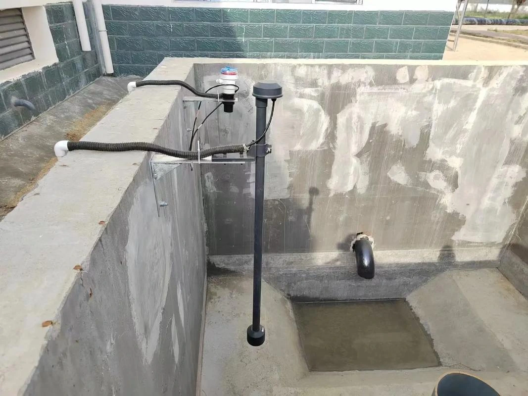
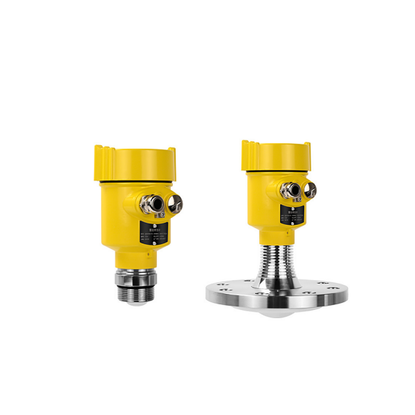
Guided wave radar level sensor is a measuring instrument based on the time-of-travel principle. Radar waves travel at the speed of light, and this travel time can be converted into a level signal by electronics. The probe emits a high-frequency pulse that travels along a cable or rod-type probe. When the pulse hits the material surface, it is reflected and received by a receiver within the instrument. It converts the distance signal into a level signal.
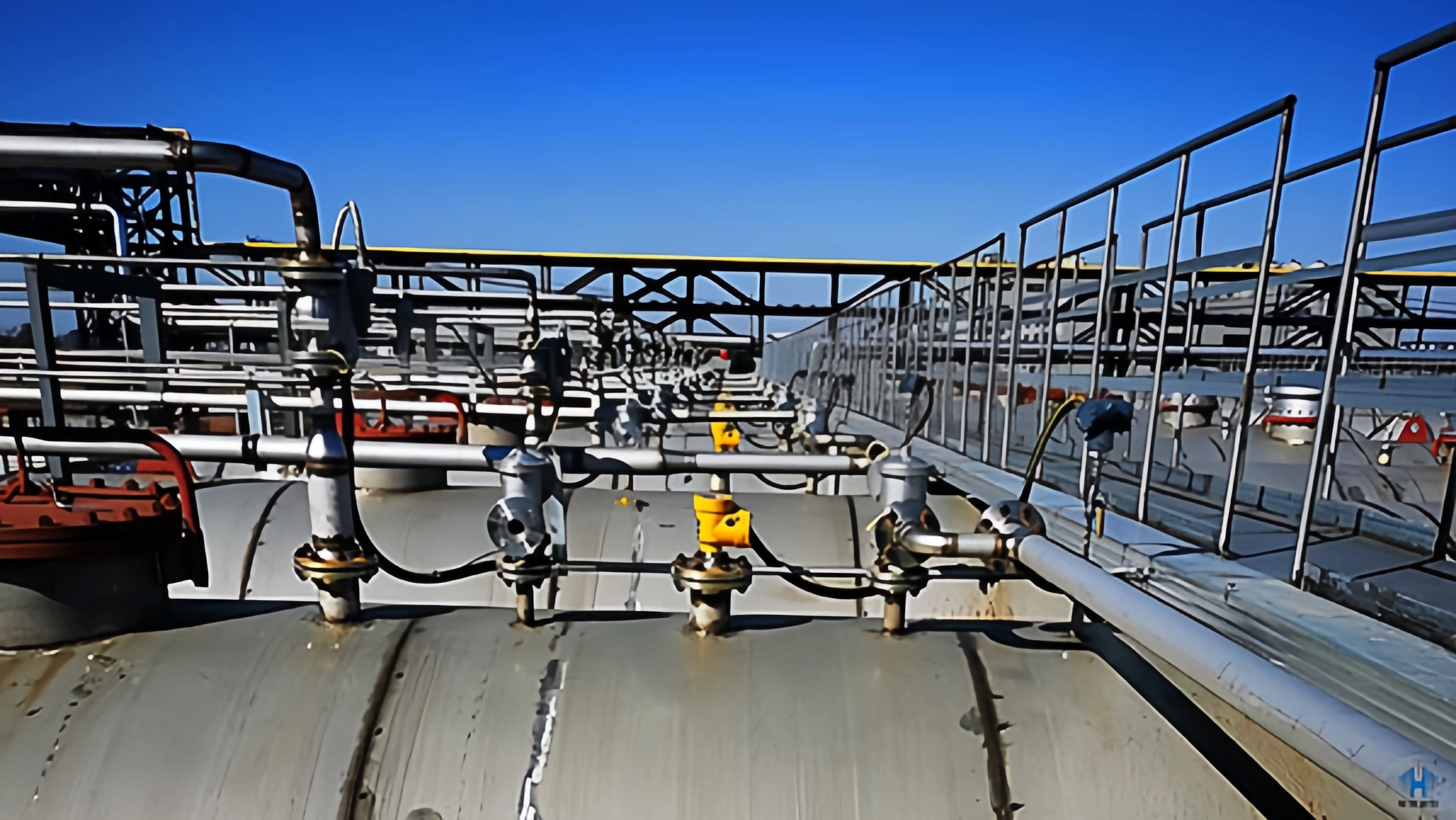
Guided wave radar level sensor has a wide range of applications and is not restricted by site conditions or constraints. They can maintain measurement accuracy in harsh environments. They operate under high temperatures and high pressures. They can also measure corrosive media. such as liquids, solids, slurry, gases, and dust.
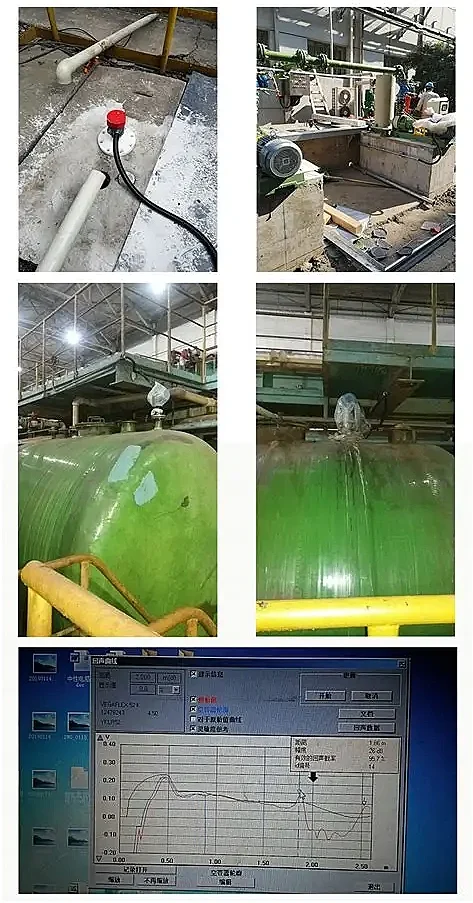
A guided wave radar level sensor may experience malfunctions during measurement. These malfunctions may be related to improper installation and maintenance. This article will detail technical issues related to guided wave radar level sensors.
Read More About Guided Wave Radar Level Sensor.

Ensure that the cable or rod does not contact internal obstructions throughout the measuring range. Therefore, installation should be avoided as much as possible within the tank. such as ladders, limit switches, heating equipment, and brackets. Additionally, ensure that the cable or rod does not intersect the feed material flow.
When installing the meter, additional considerations include:
The highest material level must not enter the measurement blind zone.
The meter must maintain a certain distance from the tank wall.
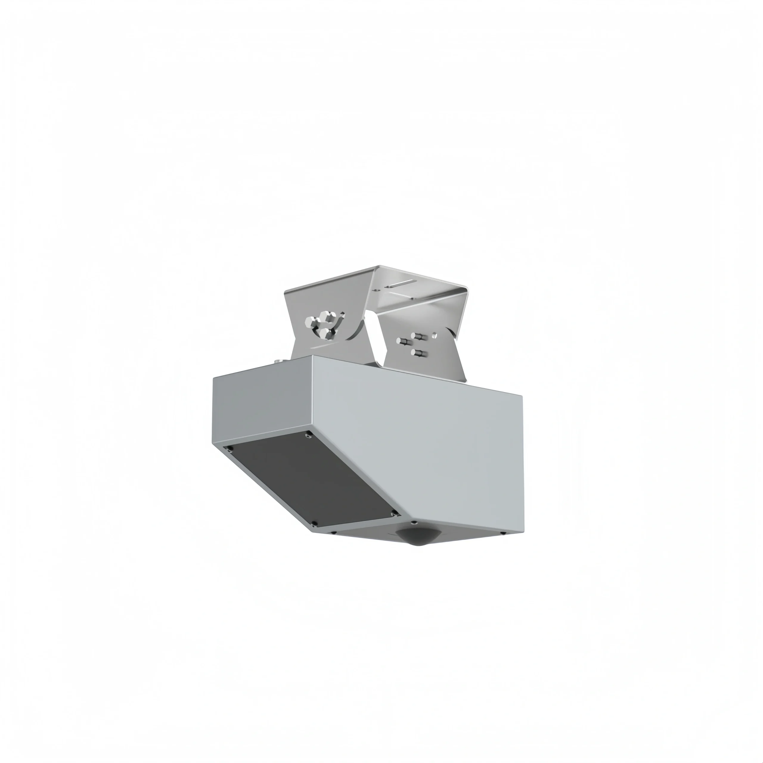
And the meter should be installed so that the cable or rod is perpendicular to the surface of the measured medium as much as possible. Instruments installed in explosion-proof areas must comply with national explosion-hazardous area installation regulations. Intrinsically safe instruments use aluminum housings. Intrinsically safe instruments can be installed in areas with explosion-proof requirements. The instrument must be grounded.
The following installation guidelines apply to cable and rod-type instruments. They measure solid powders or liquids.
Installation Location:
- Keep as far away from the discharge and feed ports as possible.
- Ensure the metal tank does not contact the tank wall or bottom throughout the entire measuring range.
- It is recommended to install the probe at 1/4 or 1/6 of the silo diameter, with a minimum distance of 1/10 of the measuring range from the tank wall.
- The minimum distance between the cable or rod probe and the tank wall is ≥ 300 mm.
- The bottom of the probe must be ≥ 30 mm from the tank bottom.
- The minimum distance between the probe and any obstructions inside the tank should be ≥ 200mm.
- If the bottom of the container is conical, it can be installed in the center of the tank top.
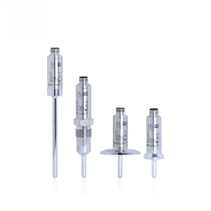
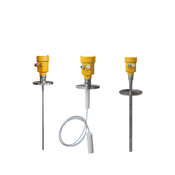
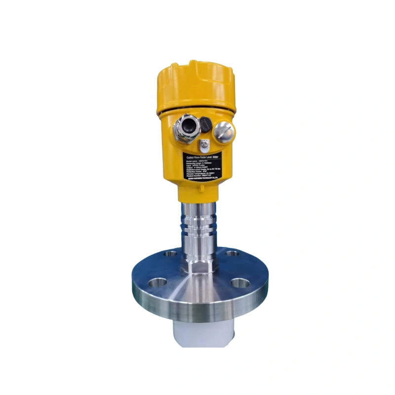
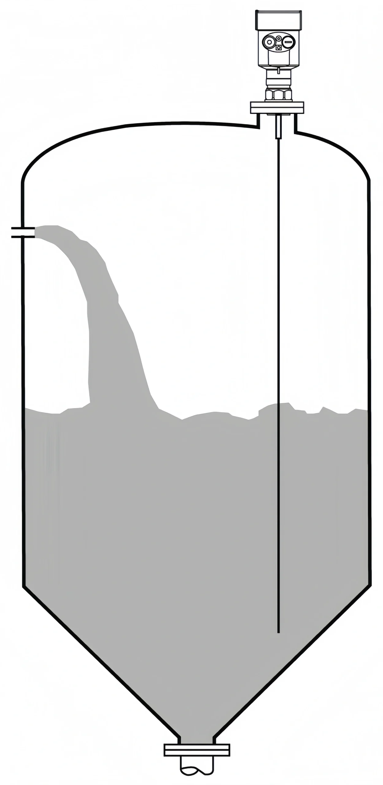
The following figure shows the installation diagram of a rod-type radar level sensor. It is primarily used for liquid level measurement.
Features:
- It can measure any medium with a dielectric constant ≥ 1.8.
- It is generally used to measure media with a viscosity ≤ 500 cst and that are not prone to adhesion.
- The maximum range of a rod-type radar is 6 meters.
- It has strong penetration capabilities against steam and foam, and measurement is not affected.
- For liquids with high foam content, a single-rod guided wave radar level sensor should be selected.
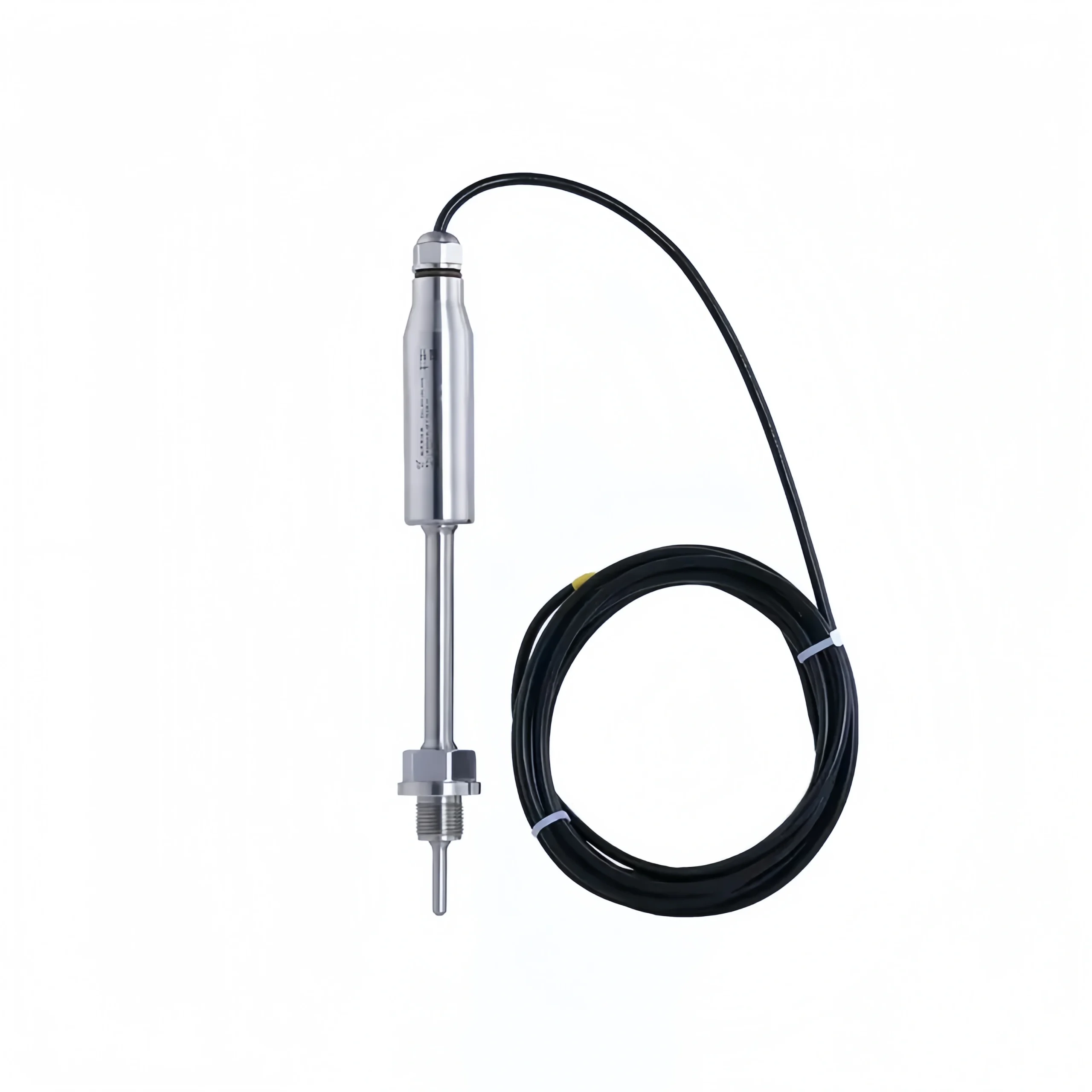
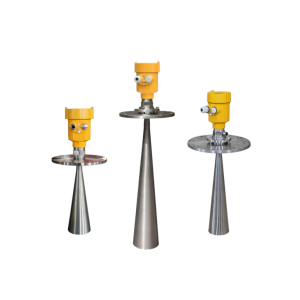
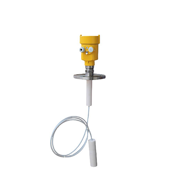
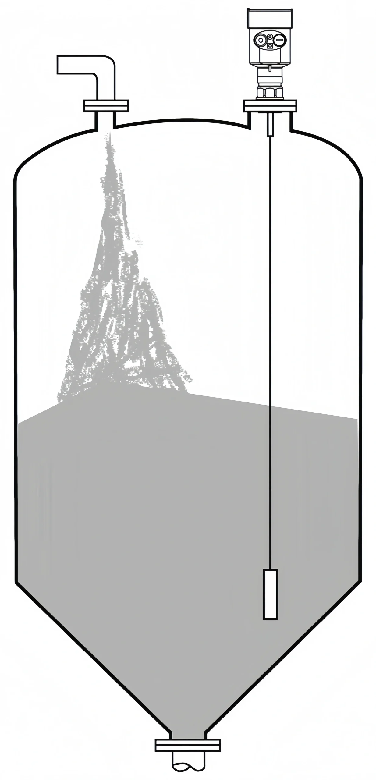
The following figure shows the installation diagram of a dual-cable radar level sensor. It is primarily used for level measurement of low-dielectric-constant liquids and low-dielectric-constant lightweight solid powders.
Features:
Liquids with relatively low dielectric constants and lightweight solid powders can be measured using a dual-cable measurement method. Ensure excellent and accurate measurement.
It can measure any medium with a dielectric constant ≥1.6.
It is generally used to measure media with a viscosity ≤500 cst and that are not prone to adhesion.
The dual-cable radar level sensor has a maximum range of 30 meters.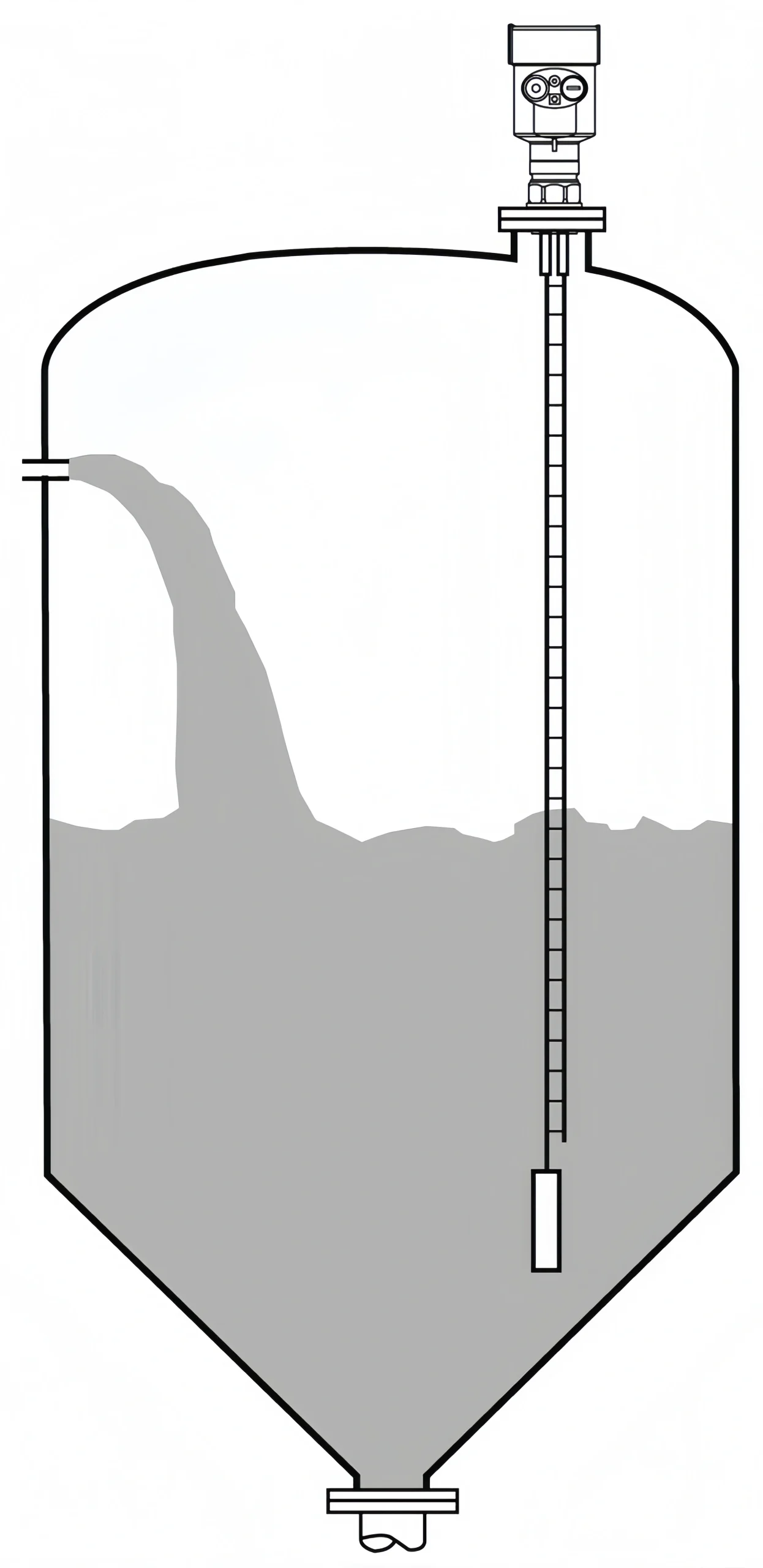
Installation Method
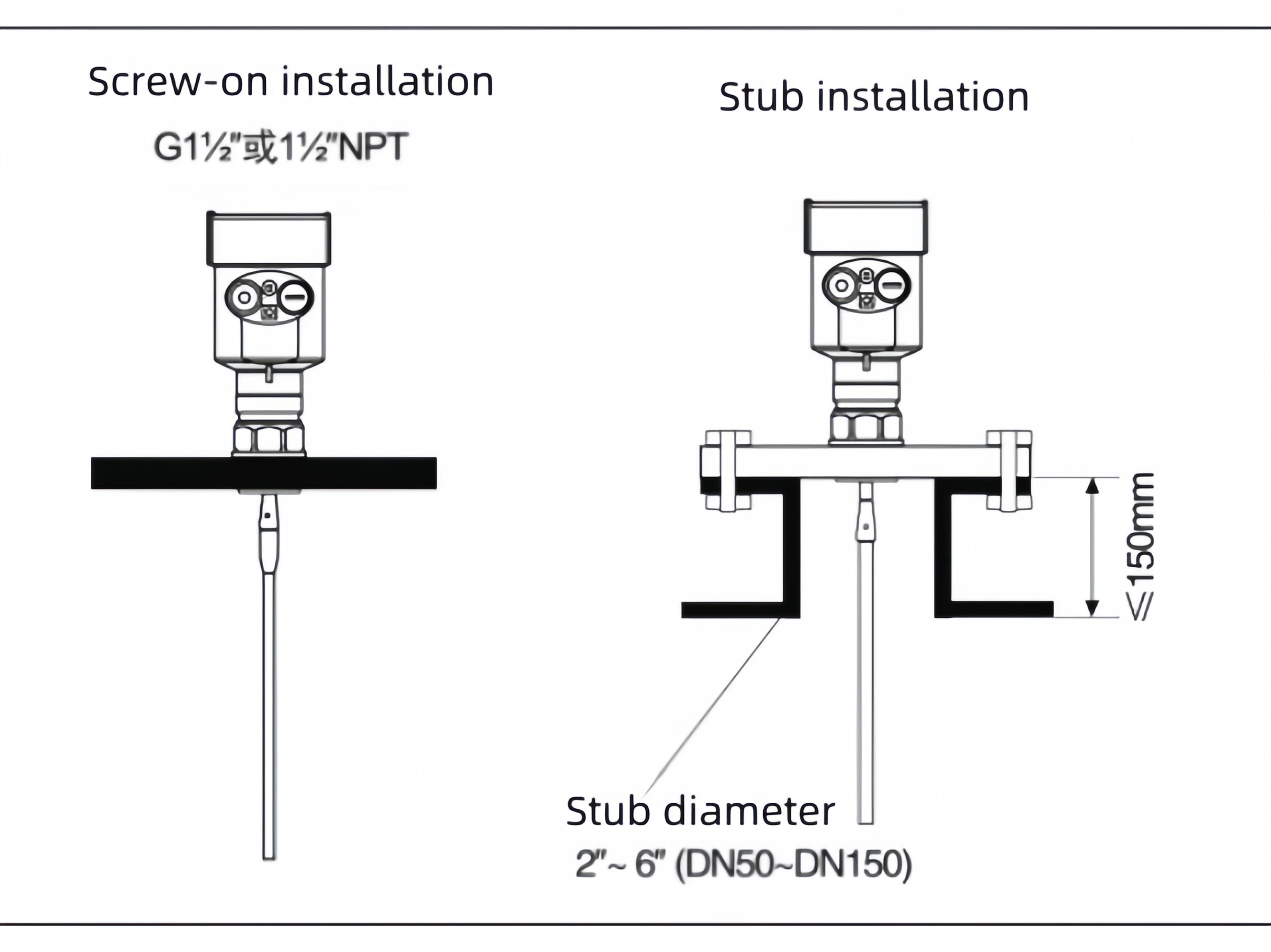
Proper installation ensures long-term reliable and accurate measurement:
Guided wave radar level sensors can be connected using threads, with the thread length limited to 15mm. They can also be installed on short pipes. When the installation short pipe diameter is between 2″ and 6″, the installation short pipe height should be ≤100mm. The shorter the thread and the short pipe length, the more stable the measurement. If the installation short pipe is longer, it is ideal to shorten the short pipe, or secure the cable probe at the bottom and use an insulated centering bracket. Prevent contact between the cable probe and the end of the short pipe.
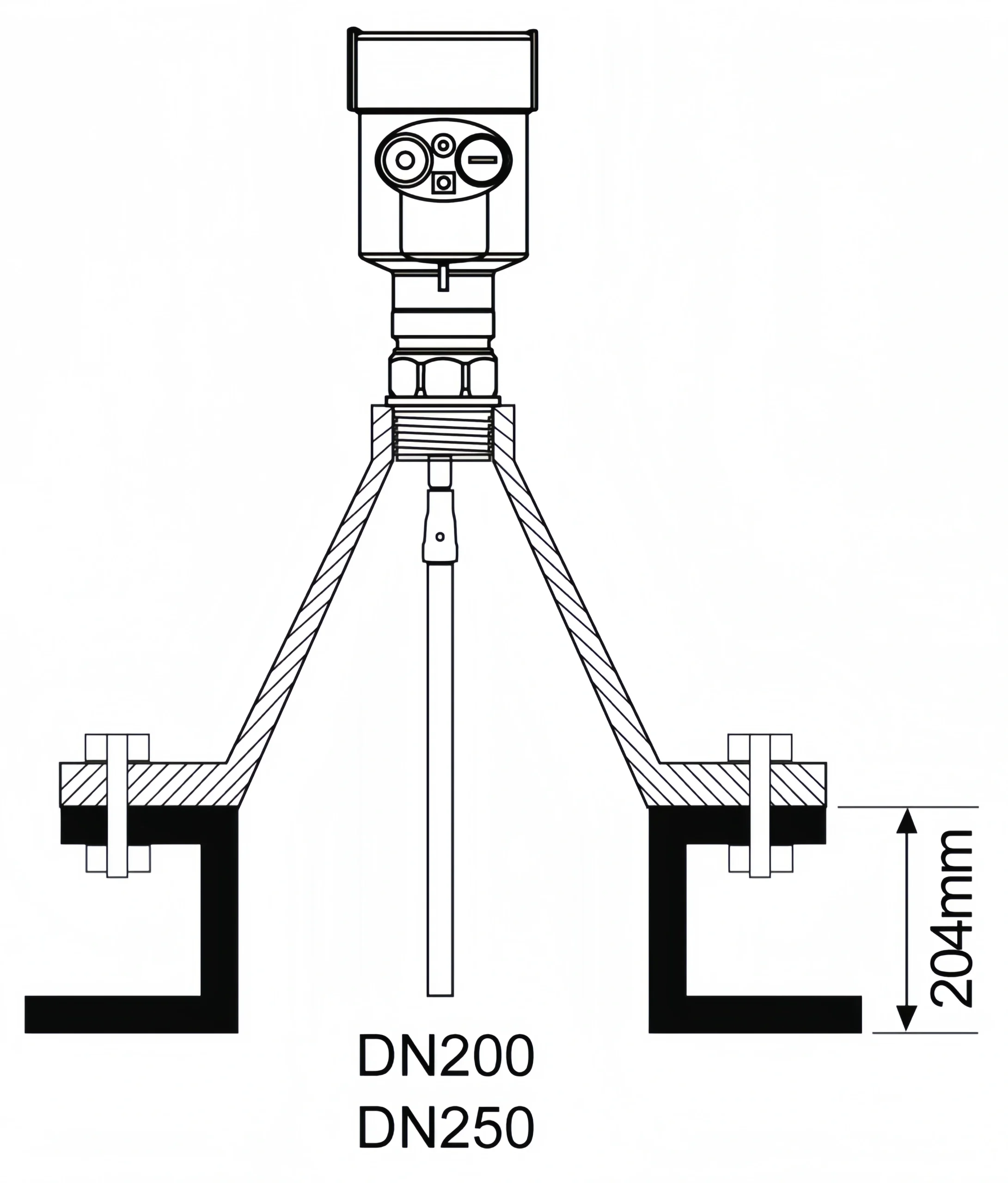
Installation in DN200 or DN250 short pipes:
When a guided wave radar is installed in a short pipe with a diameter greater than 200mm, echoes are generated on the inner wall of the short pipe, which can cause measurement errors in media with low dielectric constants. Therefore, for a short pipe with a diameter of 200mm or 250mm, a special flange with a “flare interface” is required.
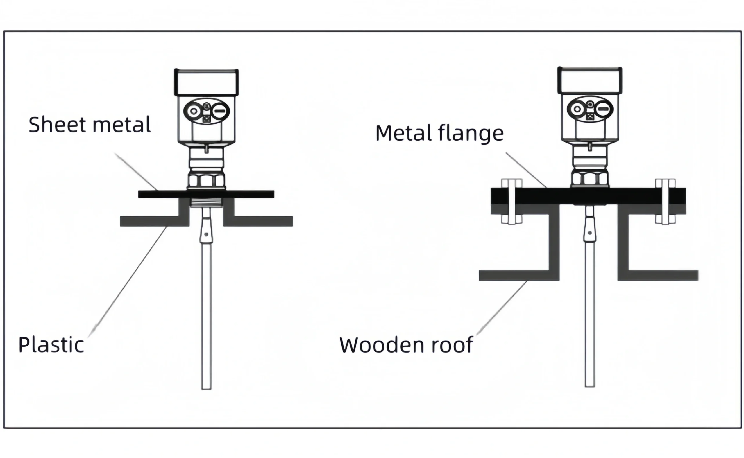
Notes on Installation on Plastic Tanks:
Whether using a cable or rod, for the guided wave radar to function properly, the process connection surface must be metal. When the guided wave radar is installed on a plastic tank, if the tank top is also plastic or other non-conductive materials. The instrument requires a metal flange. If a threaded connection is used, a metal plate is required.
 Interference Optimization
Interference Echo Suppression: The software can suppress interference echoes. Achieve optimal measurement results.
Bypass and Waveguide (applicable only to liquids with a viscosity of 500 cSt or less):
For liquids with a viscosity of 500 cSt or less, a bypass or waveguide can be used to avoid interference.
Installation for Low-Dielectric-Constant Liquids
For media with a dielectric constant greater than 1.3, a viscosity ≤500 cSt, and low adhesion, a guided wave radar can be installed in a waveguide. Its advantages are as follows:
- Excellent reliability and high accuracy
- Applicable to any medium with a dielectric constant ≥1.3, independent of the medium’s conductivity
- Measurement is unaffected by obstructions within the tank and the size of the short pipe
Corrosive Media Measurement
For corrosive media, a rod or cable probe with a PTFE or PFA sheath can be used.
Installation on horizontal and vertical tanks
- The rod probe can be up to 6 meters long. For tanks with measurement distances exceeding 6 meters, a 4mm cable probe can be used.
- The installation and mounting methods are the same as for solid powder silo measurements.
- The distance from the tank wall must be greater than or equal to 300 mm. Avoid contact between the probe and the tank wall.
- When selecting the probe length, ensure that the bottom of the probe is at least 30 mm from the tank bottom.
- If there are numerous obstacles in the tank or if the obstacles are too close to the probe sensor, a waveguide can be installed for measurement.
Special Installation Instructions:
For guided wave radars with excessively long cables during field use, the excess cable must be cut to ensure accurate measurement. The cable must not be knotted, tangled, or attached to other objects.
To cut the cable, first disconnect the instrument power, remove the cable, unscrew the weight, and cut the cable from the bottom. After cutting, reinstall the weight. Once the instrument is fully installed, reconnect the power and reset the parameters.
For cable-type guided wave radars with sleeves, if the cable is too long, do not cut it yourself; return it to the manufacturer for cutting.
For guided wave radar level sensors installed in a waveguide, use an insulating bracket to secure the radar probe. Ensure that the probe (rod/cable) is concentric with the waveguide. Otherwise, the radar waveform will oscillate, affecting the measurement.
Precautions
Guided wave radars installed in waveguides generally use a rod-type probe sensor. During installation, an insulating concentric bracket should be installed on the rod probe. Ensure that the rod probe is concentric with the waveguide. Otherwise, strong false echoes will be generated. When the measurement range exceeds the maximum range of a rod probe, a guided wave radar with a cable probe should be used. The diameter of the waveguide should be greater than or equal to 6″ (DN150). Otherwise, strong false echoes will be generated.
Correct Installation: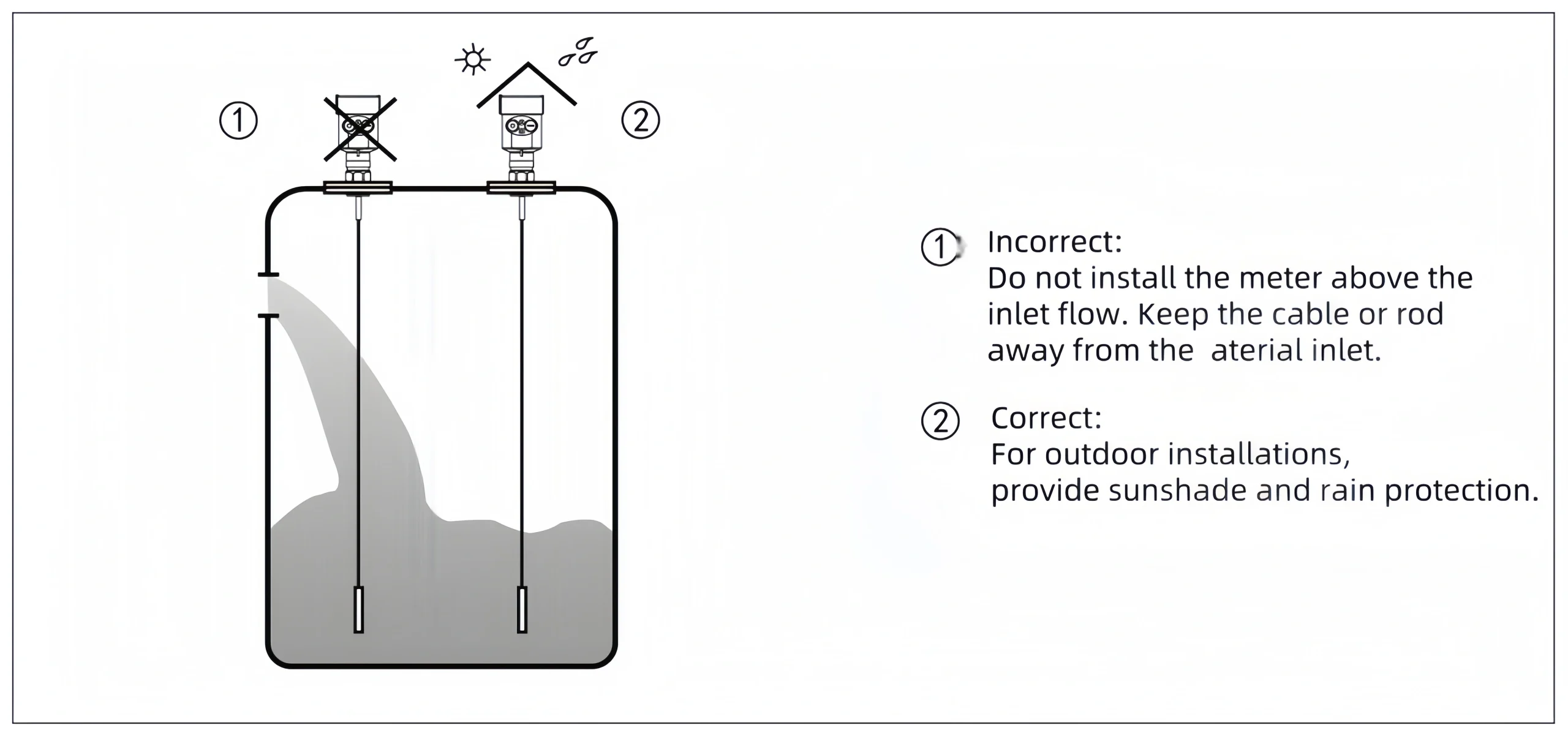
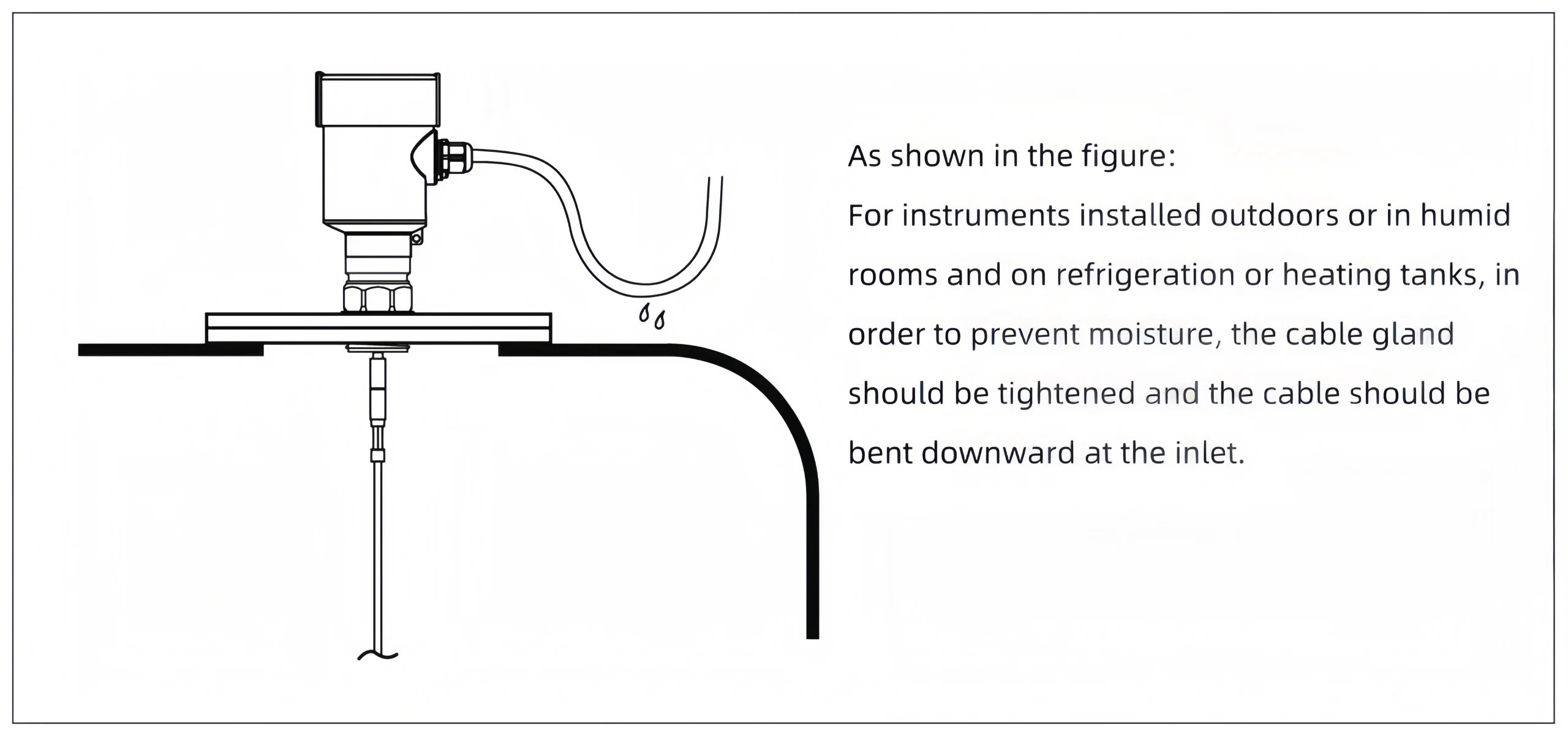
Moisture-Proof:
Calibration is crucial for measurement accuracy. Guided wave radar level sensors require calibration. Calibration results in more accurate measurements.
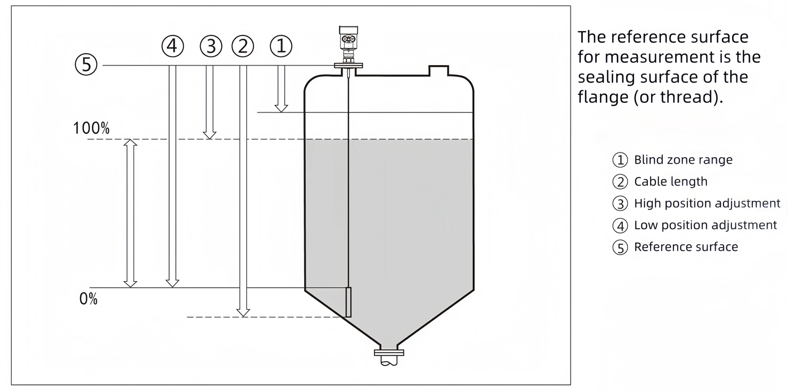
1. Parameter Setting
Setting the parameters is a critical step in the calibration process. These parameters primarily include setting parameters. such as tank shape, medium conditions, process conditions, empty tank height, full tank height, and blind zone. These parameters should be appropriately configured based on actual site conditions. Ensure accurate measurement results.
Tank Shape: Select a tank shape. such as a dome tank or a horizontal cylindrical tank based on the actual storage tank.
Medium Conditions: Accurately enter the dielectric constant of the medium. It is a key factor in calculating the liquid level.
Process Conditions: Set process conditions. such as standard state, calm surface, and fluctuating surface. To accommodate different operating environments.
Empty Tank Height and Full Tank Height: Enter the distance from the flange to the lowest liquid level (empty tank height) and the distance from the lowest liquid level to the highest liquid level (full tank height). When setting these two parameters, consider the effects of corrosion and buildup. To ensure that the end value of the measurement range is at least 50mm from the antenna tip.
Blind Zone: Set the minimum distance between the highest measurable level and the measurement reference point. Reliable level measurement cannot be guaranteed when the level falls within the blind zone.
2. Signal Adjustment and Optimization
After parameter settings are complete, the radar level meter’s signal needs to be adjusted and optimized. This includes checking the echo graph for normal display and noise interference, and adjusting parameters. such as gain and filtering as needed to improve signal quality. False echoes must also be suppressed to eliminate interference from noise on the measurement results.
3. On-site Verification and Fine-Tuning
On-site verification is an essential step in the calibration process. By comparing the measurement error with the actual liquid level, the radar level meter’s measurement error is checked. Ensure it meets accuracy requirements. If any deviation occurs, fine-tuning is required to correct the error. During the verification process, the radar level meter’s response speed and stability under different operating conditions must be carefully observed. To ensure its reliability in actual use.
Regular maintenance can extend the service life and improve measurement accuracy.
1. Sensor Maintenance
Regular Cleaning
Wipe the antenna surface with a soft cloth to prevent coking or dust accumulation from affecting the signal.
For high-temperature conditions, an ammonia purge port can be installed to remove debris from the antenna surface in real time. For high-viscosity media, the probe should be regularly disassembled and cleaned.
Calibration and Parameter Optimization
Perform zero and span calibration every six months to one year. Calibration intervals are recommended to be shortened in high-temperature environments. Use software to block false echoes from fixed obstacles and adjust gain and filter parameters to optimize signal quality. If temperature fluctuations are significant, enable dynamic vapor compensation to correct for changes in dielectric constant in real time.
Component Inspection
Inspect all components for proper operation. Regularly replace aging seals and cables. Prevent insulation failure caused by high temperatures.
2. Measuring Cointainer Maintenance Protection
Corrosion and Deformation Prevention
Inspect the cylinder wall for corrosion. Regularly apply an anti-corrosion coating (such as a ceramic coating). Monitor the thermal expansion of the cylinder wall at high temperatures. And adjust the bracket fixing points if necessary.
Drainage and Flowability
Open the drain valve at least once a week to remove sediment from the tank bottom. If the medium is prone to coking, increase the purge frequency or use steam tracing.
Sealing Test
Use soapy water or a helium mass spectrometer to check the sealing of flange joints. Bolts may loosen due to thermal expansion and contraction at high temperatures. And require regular tightening (using high-temperature bolt glue is recommended).
3. Safety and Environmental Management
Operational Safety
Disconnect the power supply before maintenance and wear high-temperature gloves and goggles. Allow high-temperature media to cool to a safe temperature before disassembling the equipment.
Environmental Monitoring
Monitor ambient temperature, humidity, and electromagnetic interference. To avoid exceeding the equipment’s rated range. For explosion-proof areas, ensure that the equipment meets the required explosion-proof rating.
 In short, we hope this article helps you resolve your issue. Guided wave radar level sensors are commonly used in industrial level measurement. Different types of level sensors can measure different media. If you’re considering a guided wave radar level sensor but are unsure which one to choose, trust Sino-Inst. We will recommend the most suitable measurement solution.