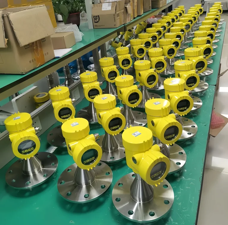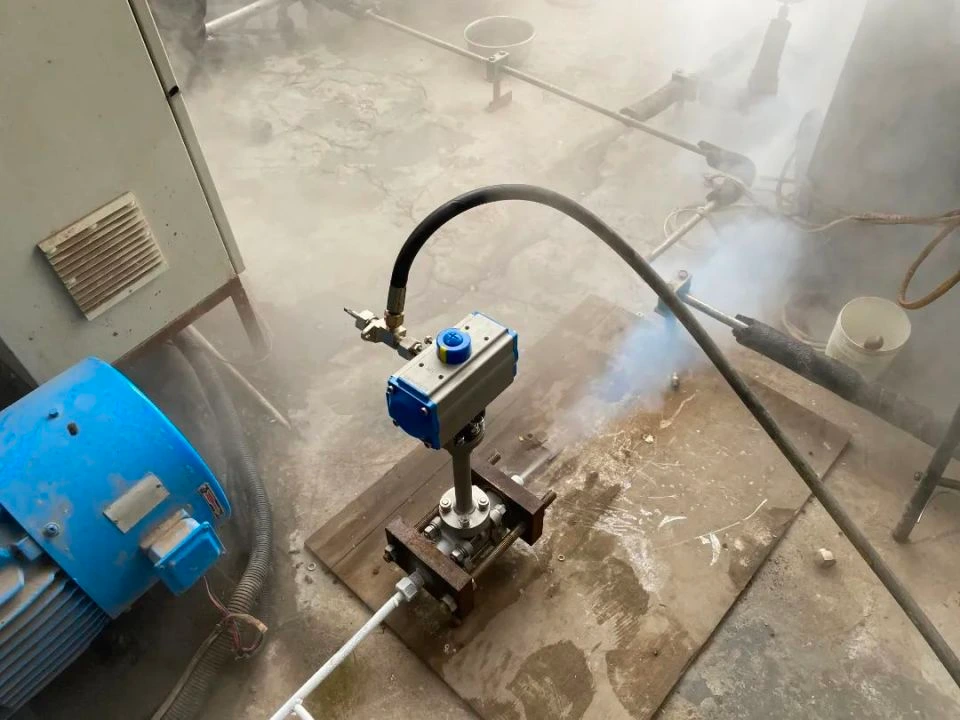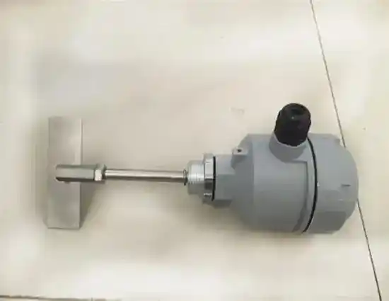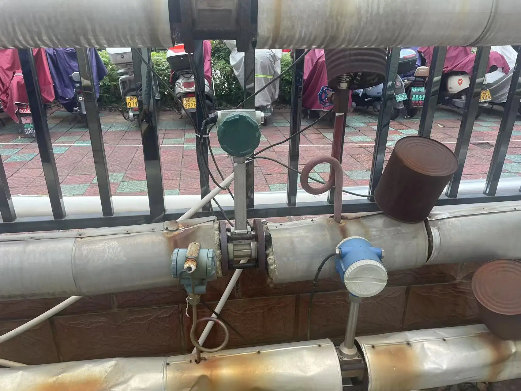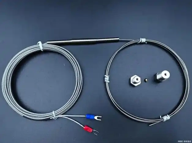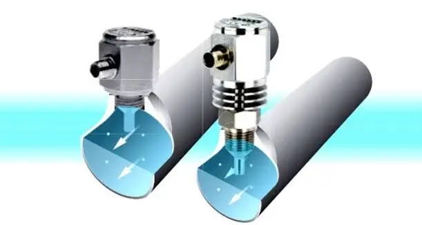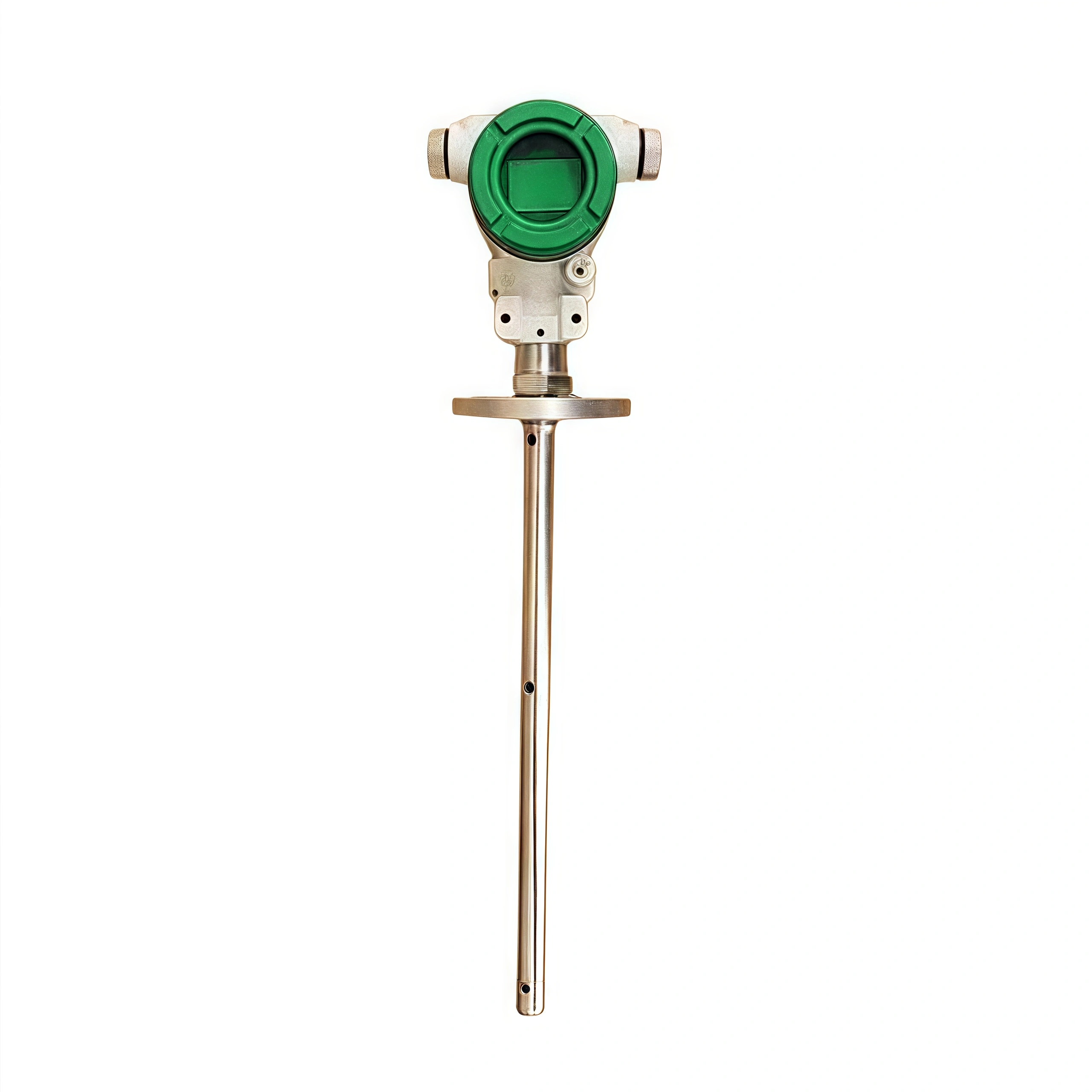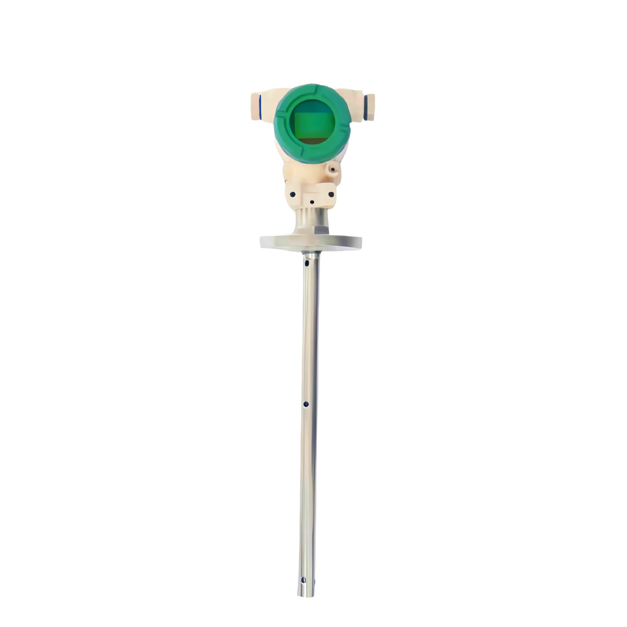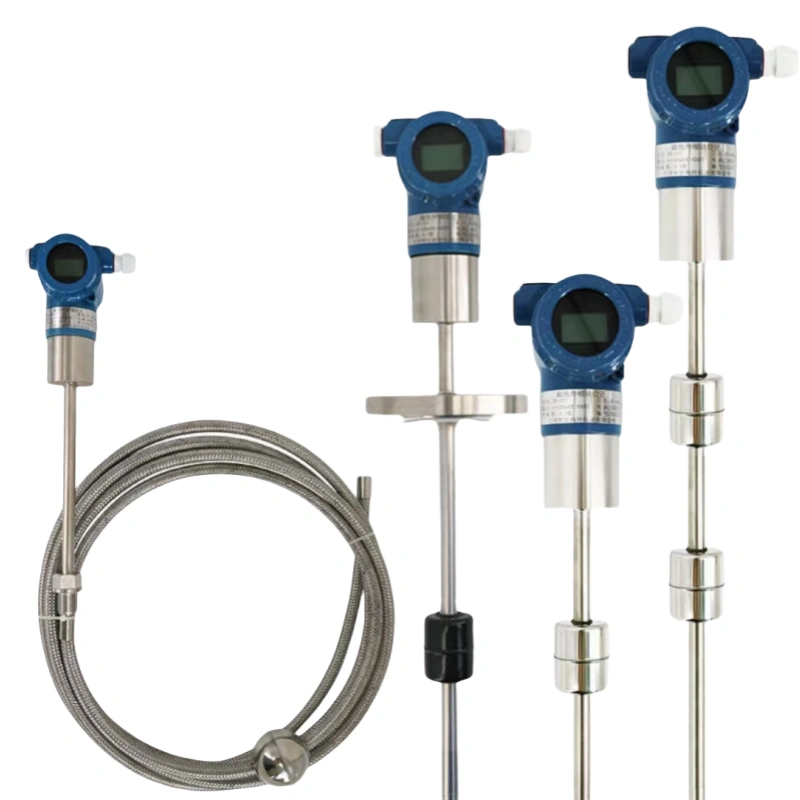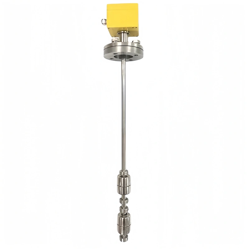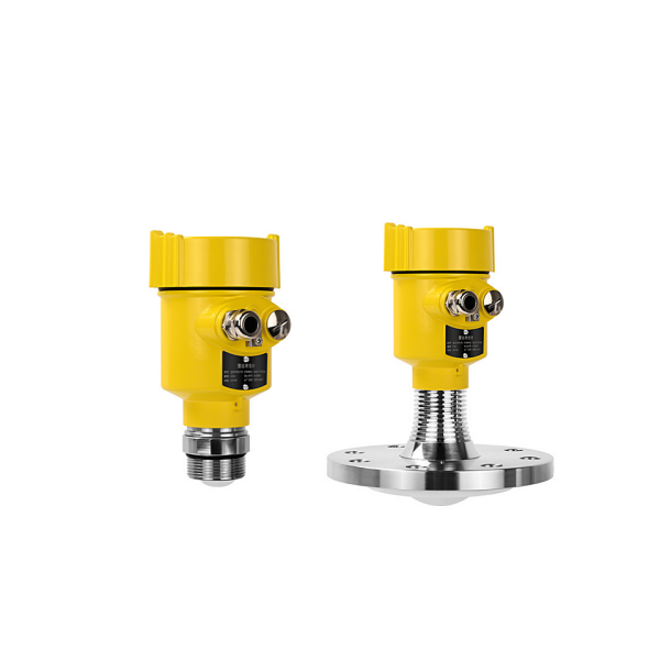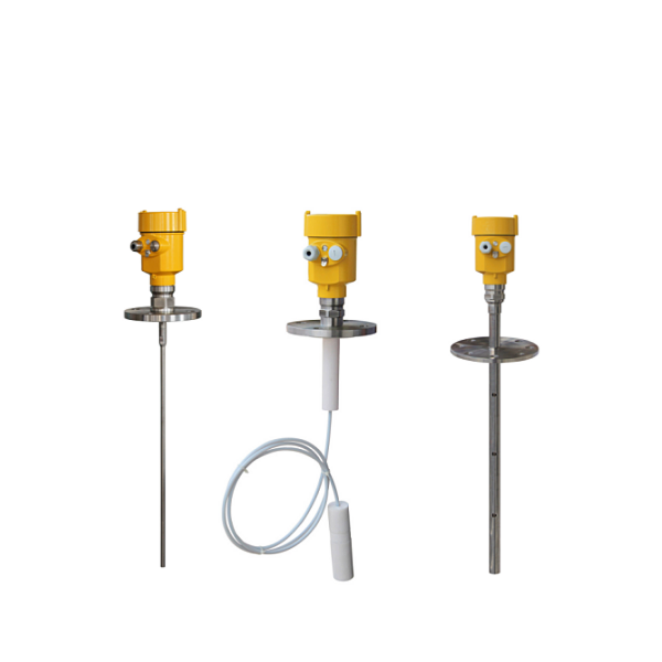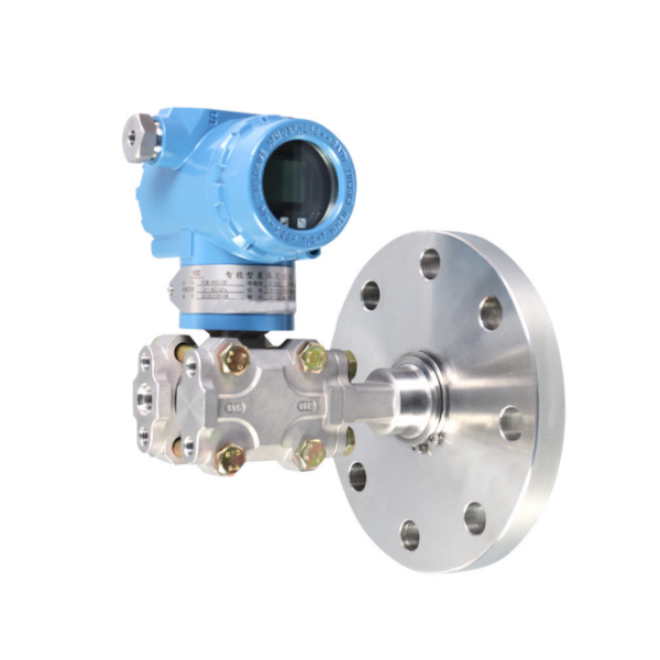
An oil tank level sensor converts the oil level within a tank into a recognizable signal, such as 4–20 mA, HART, RS485 Modbus, or relay contact signals. This device is also known as an oil level transmitter or oil level transducer.
Using oil level sensors to measure and manage tank oil levels is faster and more efficient than manual inspection. For industrial oil tanks and vehicle-mounted oil tanks, there are seven common liquid-level measurement technologies: 80 GHz radar, guided-wave radar, magnetostrictive, capacitive, hydrostatic (submersible), magnetic float, and ultrasonic. Based on our many years of experience in oil level measurement at Sino-Inst, we will analyze and introduce this topic for you.
| Type | Typical range | Accuracy (our models) | Good for | Watch out for |
|---|---|---|---|---|
| 80 GHz FMCW radar | 0.1–150 m | up to ±1 mm | Large storage tanks, heavy oil, used oil, heated tanks to 280 °C | Thick foam; low-εr oil in small tanks with many internals — use a stilling well |
| Guided wave radar | up to 30 m | ±10 mm | Pressurized tanks, oil/water interface, vapor space | Heavy coating on the probe; very viscous oil |
| Magnetostrictive | 0.3–25 m | linearity ±0.02 %FS | Diesel and lube oil day tanks, inventory, two-float interface | Needs float density margin; sticky or waxy oil |
| Capacitive (coaxial) | 0.1–5 m (fuel/oil type) | Class 0.5 | Generator and hydraulic tanks, small vessels | Must be calibrated on the actual oil; water at the bottom shifts the reading |
| Hydrostatic (submersible) | 0.5 m and up | 0.2–0.5 %FS | Open or vented tanks, low cost | Reads wrong if oil density is not set; not for pressurized tanks without DP compensation |
| Magnetic float (reed chain) | 0–6 m | ±10 mm | Simple tanks, local plus 4–20 mA | Max about 120 °C / 1.6 MPa (PP/SS type); viscous oil |
| Ultrasonic (top-mounted) | 5–20 m (Ex model) | 0.3 % | Clean, cool oil in vented tanks | Vapor, foam and heated tanks attenuate the echo |
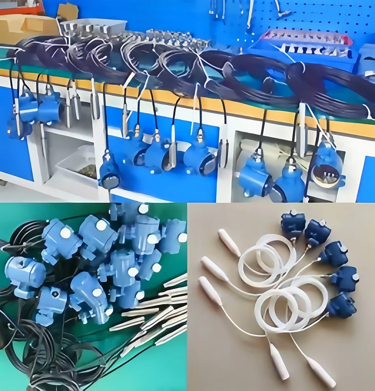

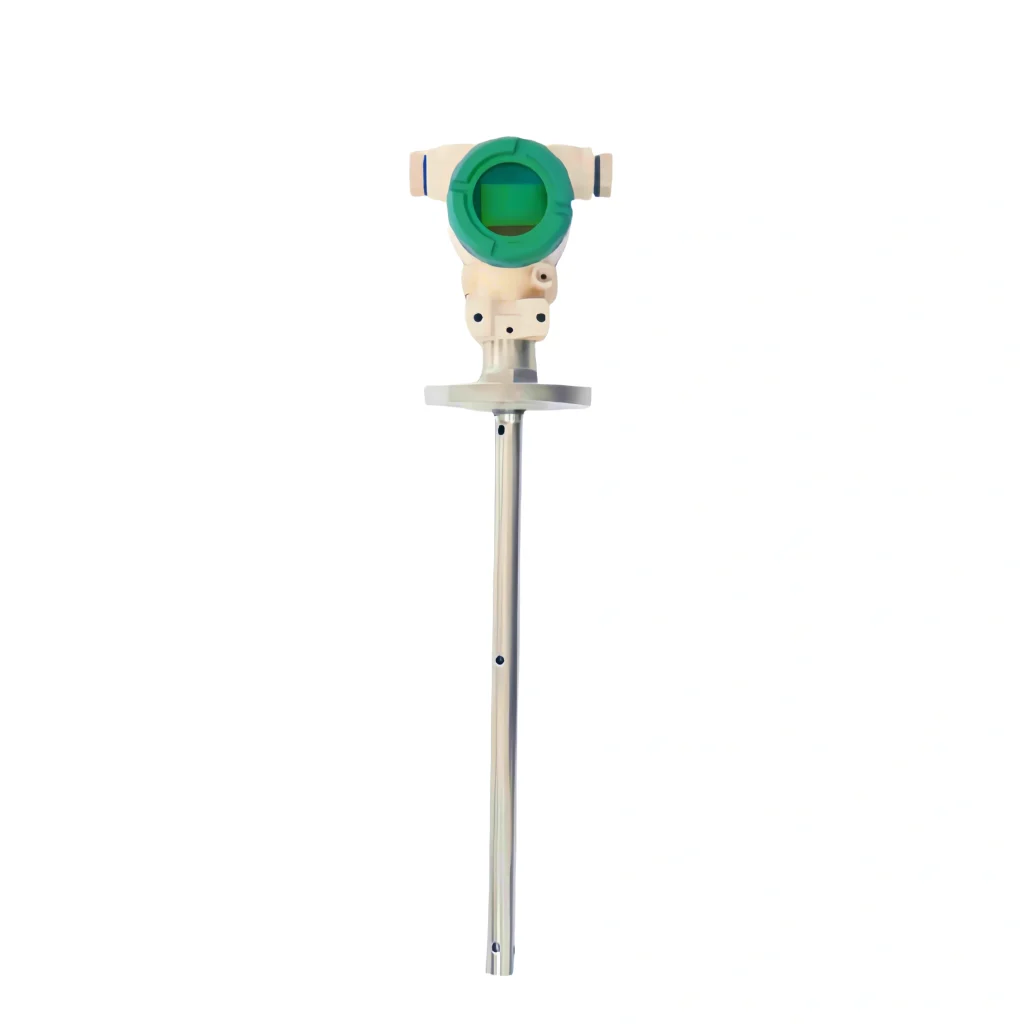
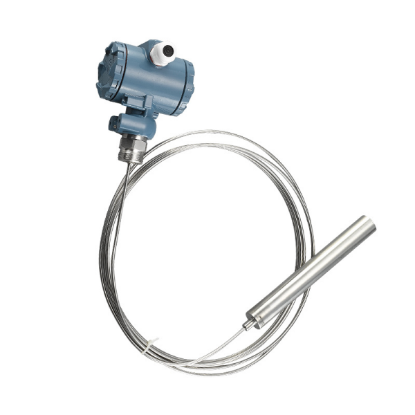
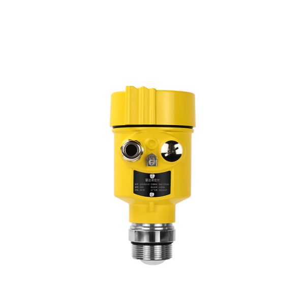
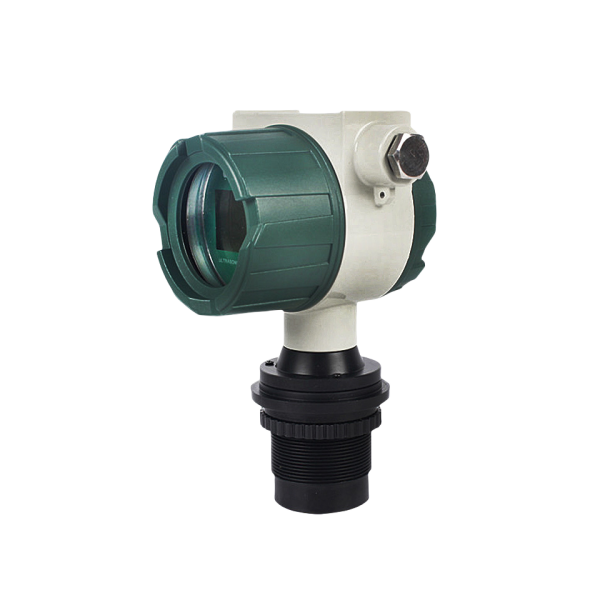
Simply put, an oil level sensor (also known as an oil level transmitter) is a sensor used to measure the height of oil-based liquids. These sensors can be mechanical or electronic in nature and are capable of either continuous level monitoring or point-level control. Ultimately, the purpose of an oil level sensor is to enhance the efficiency of monitoring oil levels within storage tanks.
We can categorize them simply:
First, there are traditional mechanical oil level sensors, which use mechanical principles to measure and display the oil level. Examples include float gauges and magnetic level gauges. They use physical principles, such as buoyancy and magnetism, to indicate liquid levels. No power supply is required, and therefore, there is generally no signal output.
Second, there are electronic oil level sensors, which require a power supply (commonly 24V DC or 220V AC) to function. Examples include 80 GHz radar level gauges and ultrasonic level gauges. These offer higher measurement accuracy, support the adjustment of measurement parameters, and provide standardized output signals—such as 4–20 mA, RS485, or HART protocols. They significantly improve the precision and efficiency of liquid monitoring in industrial oil tanks. Furthermore, electronic sensors can be integrated with PLCs or volume recording instruments to calculate the total volume or mass of the oil.
Finally, there are sensors designed for point-level measurement and control, often called oil level switches or controllers—for instance, float switches or tuning fork-type sensors. These sensors cannot perform continuous level monitoring; instead, they output a relay-based switching signal when a specific, fixed level is reached. They are primarily used for level control applications.
Why Sino-Inst Oil Level Sensors
- Accuracy from ±1 mm (80 GHz radar) to ±10 mm (guided wave radar and float)
- Outputs: 4–20 mA, HART, RS485 Modbus or relay contacts
- Process temperature up to 280 °C (80 GHz radar) and 320 °C (magnetostrictive)
- Explosion-proof versions with China Ex certificate
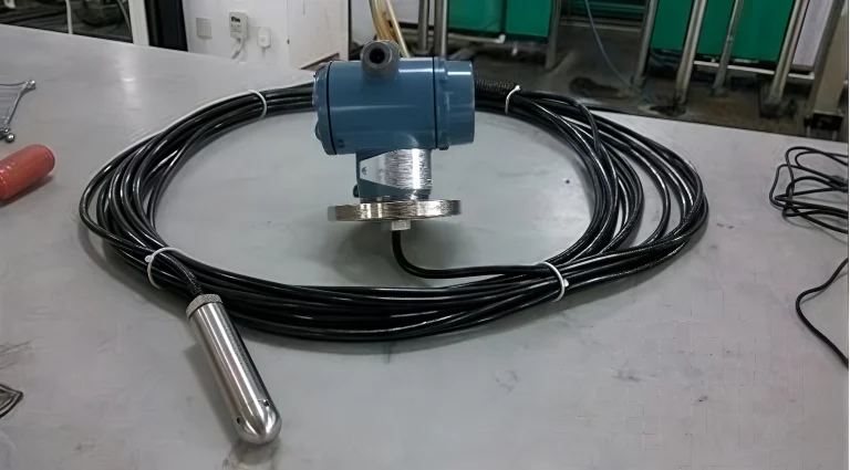
Oil level sensors work on several principles: radar (including guided wave radar), magnetostriction, capacitance, hydrostatic pressure, ultrasonic and magnetic float. Each one measures the height of the oil in the tank.
Radar oil level sensor
Working principle: The transmitter measures the distance to the oil surface in three steps:
- Emits a microwave signal from the antenna toward the oil surface
- Receives the echo reflected by the surface
- Converts the time of flight (pulse) or frequency difference (FMCW) into distance, then level = tank height − distance
Installation: Keep it off the tank center, where a dome roof focuses false echoes. Mount it at least 1/6 of the tank diameter (and no less than 200 mm) from the wall, and never above the filling inlet, where the falling stream blocks the signal.
Applications: Crude and refined oil storage tanks, heavy oil and bitumen tanks, used-oil tanks.
Advantages: Vapor and temperature changes do not affect it. Thick foam can weaken the echo; on foaming oil use guided wave radar instead. The radar level sensor does not contact the liquid, reducing the risk of contamination and mechanical wear.
User case (Estonia, pyrolysis oil): A distributor needed level and temperature measurement on tanks holding pyrolysis oil with gas in the headspace, at 0–150 °C and up to 10 bar. We supplied two FMCW 80 GHz radar level transmitters and two PT100 temperature sensors (100 mm insertion, 1/2″ NPT). The original specification asked for ATEX Zone 0/1; our radar carries a China Ex certificate, and the customer confirmed that rating was acceptable before ordering.
Magnetostrictive oil level sensor
Working principle: The magnetostrictive oil level sensor mainly consists of a magnetostrictive wire, a measuring rod, an electronic chamber, and a float fitted onto the measuring rod. By measuring the time interval for a torsional wave—triggered by a current pulse—to travel along the waveguide wire and return, the position of the float can be determined, allowing for the precise calculation of the liquid level. Its core is based on the magnetostrictive effect and the time difference measurement principle.
These sensors are available with Modbus output or as two-wire units supporting the HART protocol. They can also be configured as multi-point temperature sensors to monitor temperatures at various depths within the liquid. This series of products covers a measuring range of 0.3–25 meters and has a linearity of ±0.02% FS.
Installation: Top-mounted (via flange or threaded connection), with the probe rod or a flexible cable extending toward the bottom of the storage tank.
Applications: Used for daily-service tanks and bulk storage tanks containing diesel or lubricating oil; also capable of measuring oil/water interfaces through the use of a dual-float system.
Limitations: The float needs a sufficient density difference to stay on the liquid surface; if the oil contains wax or has extremely high viscosity, it may form an adhesion layer on the surface of the float.
Guided wave radar oil level sensor
Working principle: It transmits microwave pulses along a waveguide rod or cable and receives the reflected echoes. By measuring the round-trip time, it accurately calculates the liquid level height. Microwave pulses propagate downwards along the rod or cable probe and are reflected at points where the dielectric constant changes (i.e., the oil surface and the oil/water interface below). The measurement range extends up to 30 meters, with an accuracy of ±10 mm.
Installation: Top-mounted; the probe should be positioned at least 300 mm away from the tank wall and kept clear of inlet/feed ports. Alternatively, it can be installed within a bypass chamber (bypass pipe).
Applications: Pressure vessels, storage tanks containing vapors or condensates, and oil/water separation tanks.
Limitations: Significant buildup of deposits on the probe or extremely high viscosity of the liquid can lead to measurement inaccuracies.
Capacitive oil level sensor
Working principle: The liquid level height is calculated by the change in capacitance formed between the probe and the container. Oil has a dielectric constant of about 2 and air is 1, so the capacitance rises as the oil level rises. Because the difference is small, oil applications use a coaxial probe and are calibrated on the actual oil. The transmitter converts the capacitance into an output signal proportional to the level.
Installation: Top mounted through a threaded or flanged nozzle.
Applications: Generator day tanks, hydraulic reservoirs, lube oil tanks.
Limitations: Water settling at the bottom or a change of oil type changes the reading; recalibrate after switching oils.
Hydrostatic (submersible) oil level sensor
Working principle: A pressure sensor at the tank bottom measures the oil level from the pressure of the oil column: P = ρgh, so h = P / (ρg). The transmitter must be set to the oil’s density — diesel is about 0.82–0.85 kg/L, not 1.0 like water. As the level rises or falls, the pressure changes and the output signal follows.
Installation: Lowered through a top nozzle or manhole to the tank bottom, or flange-mounted on the side near the bottom.
Applications: Vented storage tanks, day tanks and open sumps.
Advantages: Low cost and simple; foam and vapor above the oil do not affect it. Explosion-proof versions are available.
Limitations: Accuracy depends on density; oil density drops about 0.7–0.8 % for every 10 °C rise, so heated tanks need temperature compensation.
User case (Malaysia, diesel in a horizontal tank): A wood-processing plant uses one of our submersible hydrostatic level transmitters on a horizontal cylindrical diesel tank. The customer asked whether the transmitter had been calibrated for diesel. We sent a short video showing how to set the density to 0.85, the value for diesel. They also asked whether it could display litres. It cannot: the transmitter outputs level only, and because a horizontal tank is not linear, the level-to-volume conversion has to be done in the PLC or a volume display unit.
Ultrasonic oil level sensor
Working principle: The sensor is mounted above the oil. It sends and receives ultrasonic pulses and measures their delay time; distance = speed of sound × time ÷ 2, and level = tank height − distance.
Installation: Mounted on top of the tank, looking down at the oil surface.
Applications: Vented tanks holding clean oil at ambient temperature.
Advantages: Non-contact, easy to install, no moving parts.
Limitations: Oil vapor, foam and temperature gradients in the air space weaken or slow the sound; not recommended for heated or pressurized tanks.
Magnetic float oil level sensor
Working principle: A float with a built-in magnet rides on the oil and slides along a guide tube. Inside the tube, a chain of reed switches and resistors forms a voltage divider; the magnet closes the reed switch at its height, so the output changes in small steps as the level moves.
Installation: Top, side, side-bottom or bracket mounting.
Applications: Lube and hydraulic oil tanks, transformer conservators, underground storage tanks and other open or pressurized vessels.
Advantages: It is fully sealed, with no leakage path. Standard PP/SS versions run to about 120 °C and 1.6 MPa, and PP or PTFE floats handle corrosive media.
Limitations: It is in direct contact with the medium, the float seal requirements must be strict, and it cannot measure viscous media. Iron particles in the oil can stick to the magnetic float and make it hang up.
Oil/Water Interfaces and Waste Oil Tanks
In storage tanks, water typically settles beneath the oil; in waste oil tanks, sludge and foam may also accumulate at the top. If the level sensor can only detect the top surface, it will result in an overestimation of the oil level.
If the oil/water interface is clear, a magnetostrictive transmitter with a second (interface) float can be selected, or a guided wave radar can be used. However, neither of these methods can distinguish sludge at the bottom of the tank from the oil/water mixture; for waste oil storage tanks, it is recommended to use non-contact 80 GHz radar to avoid float or probe failure due to dirt buildup.