There are a variety of factors to consider when measuring natural gas flow. These include gas properties, such as its compressibility, temperature and pressure, gas composition, impurities and moisture. There is also the type of meter, environmental conditions, and specific application requirements. These factors ensure reliable and accurate readings in applications, such as legal-for-trade metering, process control and regulatory compliance.
Importance in Various Industries
Natural gas flow measurement is critical for a variety of applications. It involves measuring the flow rate of natural gas using specialized flow meters. Usually measured in units of volume or mass.
In the energy industry, they are essential for managing energy production, ensuring accurate billing and optimizing energy production. In manufacturing and industrial processes, natural gas flow meters help with process control, ensuring efficient use of natural gas. In utilities, they ensure accurate measurement of natural gas flow meters.
How to measure natural gas flow?
Natural gas flow measurement is a complex process. Multiple factors can affect the accuracy of natural gas flow measurement. Gas composition can affect the accuracy and suitability of the flow meter. Natural gas flow is measured using various types of flow meters. High-precision applications require more complex and expensive flow meters. Each flow meter uses a different principle to determine flow. And each has its advantages and disadvantages.
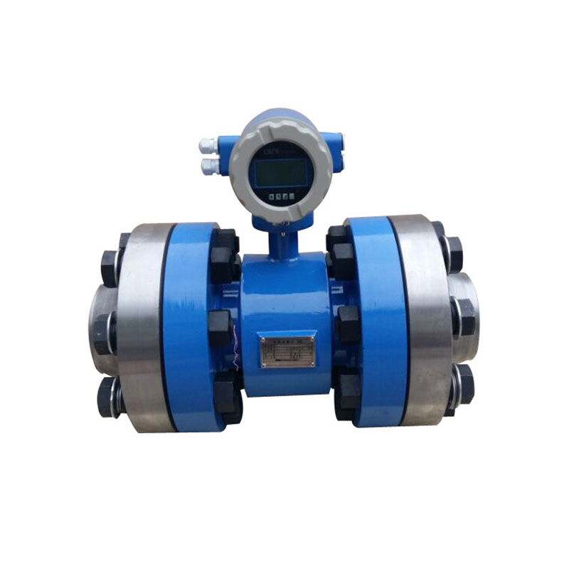
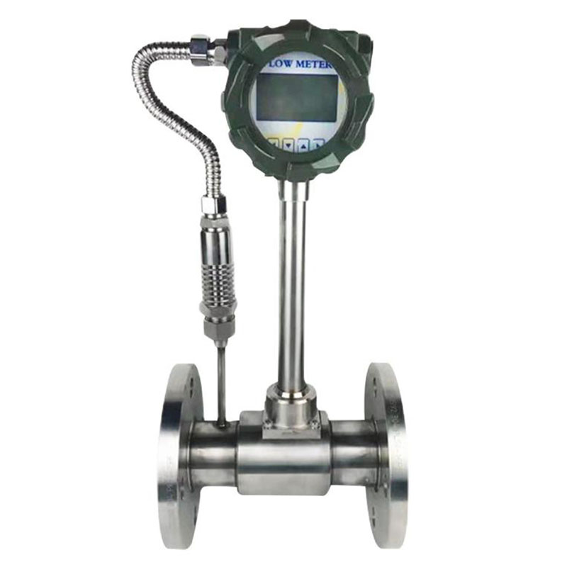
What is a natural gas flow meter?
A natural gas flow meter is a precision device. It is used to measure the rate at which natural gas flows through a pipeline. It is a tool that helps quantify the amount of natural gas flowing through a system in a specific period of time.
Natural gas flow meters measure the flow rate of natural gas. It is usually expressed in units such as cubic feet per minute (CFM) or standard cubic feet per minute (SCFM). It is a key component in a variety of industrial and commercial applications. There are many types of these meters. These include differential pressure flow meters, thermal mass flow meters, ultrasonic flow meters, etc.
Types of Natural Gas Flow Meters Used for Measurement
Natural gas flow meters can be classified according to their working principle. Here are some common types:
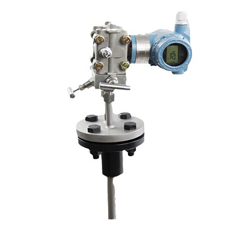
1. Differential pressure flow meter
Working Principle
A differential pressure flow meter creates a pressure drop across a restriction (such as an orifice plate) and measures the pressure difference to calculate flow. Common types include orifice flow meters and venturi flow meters.
Advantages
- The standard orifice plate structure is adopted, which is easy to copy.
- Simple structure, stable and reliable performance, long service life and low price.
- The application range is extremely wide. It is suitable for liquid, gas and steam.
- General production process and pipe diameter. There are products for all working conditions (pressure, temperature).
- The implementation and maintenance costs are relatively low.
Disadvantages
- The nonlinear relationship between differential pressure and flow limits the range of flow that can be accurately measured.
- Because the instrument signal is the square of the flow, the range is narrow, generally only 3:1~5:1;
- Proper installation (including straight pipe sections) is critical to accuracy. And it can be complicated.
- Primary elements (such as orifice plates) may cause clogging or scaling.
- High pressure loss.
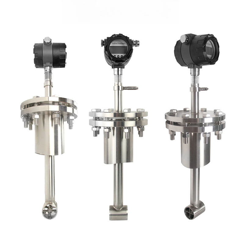
2. Thermal Mass Flow Meter
Working Principle
Thermal mass flow meter is based on the laws of heat transfer. It is an instrument that directly measures the mass flow rate of gas. Thermal mass flow meter is widely used in many industries. Applications such as HVAC systems, biogas monitoring and industrial gas flow measurement.
Advantages
- Thermal mass flow meter can provide accurate measurement. And is known for consistent results over time.
- Not affected by pressure and temperature changes.
- No moving parts.
- Generally less resistance to flow than other types of flow meter
- Direct mass flow measurement
Disadvantages
- Measurement accuracy may be affected by fluid composition and thermal properties.
- Thermal mass flow meter sensitivity may decrease at high flow rates.
- Moisture or dust particles can affect measurement accuracy.
- Limited accuracy compared to other technologies.
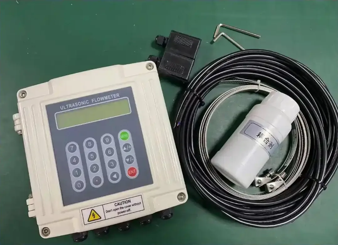
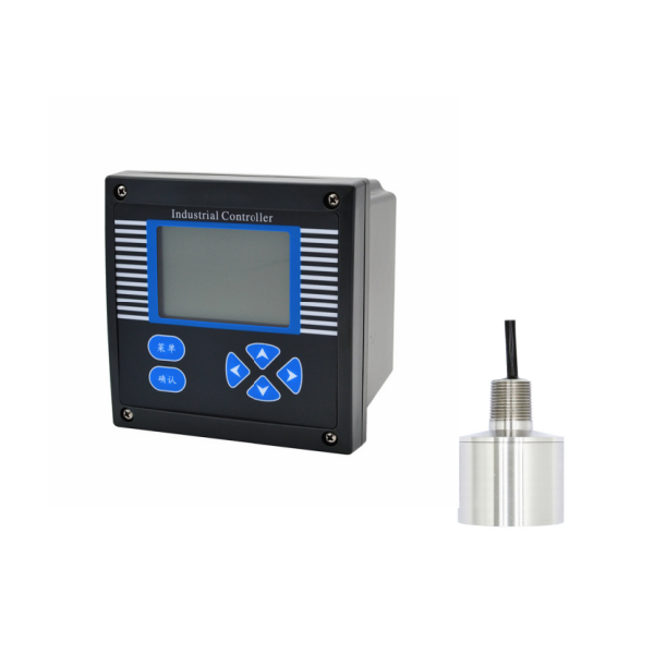
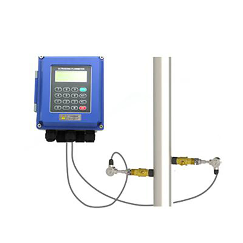
3. Ultrasonic Flow Meter
Working Principle
Ultrasonic flow meters use sound waves to measure gas flow rate. They measure the time it takes for the sound wave to travel through the fluid to calculate the volume flow rate. There are two main types: time difference method and Doppler shift method. Ultrasonic flow meters are widely used in various industries. They have accurate non-invasive measurement capabilities.
Advantages
- Non-invasive installation, suitable for clean and dirty fluids.
- No moving parts, which reduces wear and tear. Low maintenance costs.
- High accuracy.
Disadvantages
- Not suitable for liquids with high concentrations of suspended solids or bubbles.
- Requires straight, unobstructed pipe sections for best performance.
- Requires external pressure/temperature compensation for accurate mass flow.
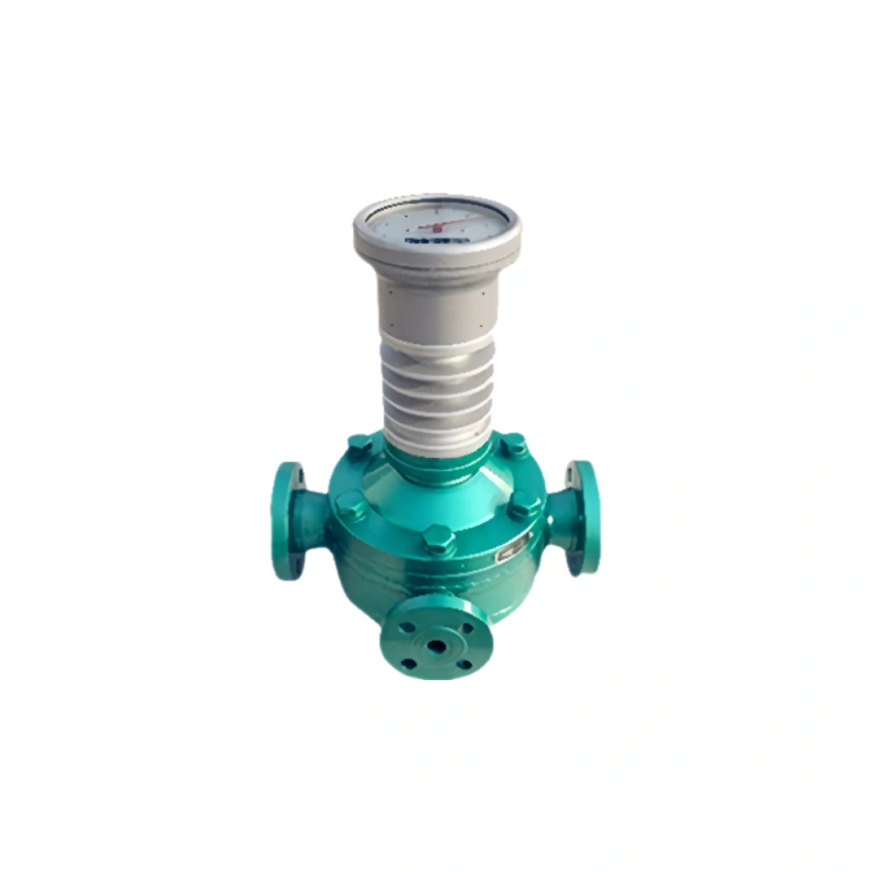
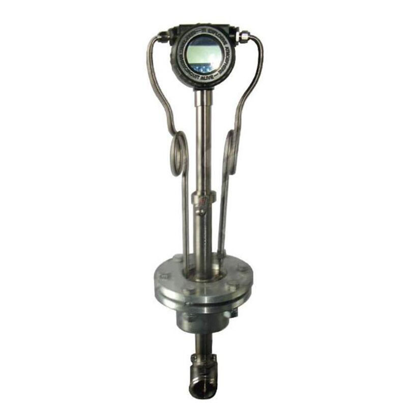
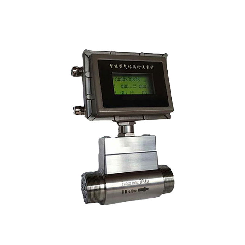
4. Turbine Flow Meter
Working Principle
Turbine flowmeters measure gas flow using a turbine rotor that rotates as the fluid flows through it. Turbine flowmeters excel in measuring medium and high-speed fluids and steady flows. They are especially suitable for clean, non-corrosive gases.
Advantages
- High accuracy and precision. Accuracy is typically within ±0.5%, and even higher accuracy can be achieved.
- Wide flow range. Including low and high flow applications.
- Applicable to liquids and gases.
- They are simple in design and relatively easy to install and maintain.
- Low pressure drop.
Disadvantages
- The physical properties of the fluid have a great influence on the flow characteristics.
- Requires regular calibration to maintain long-term accuracy.
- Not suitable for steam.
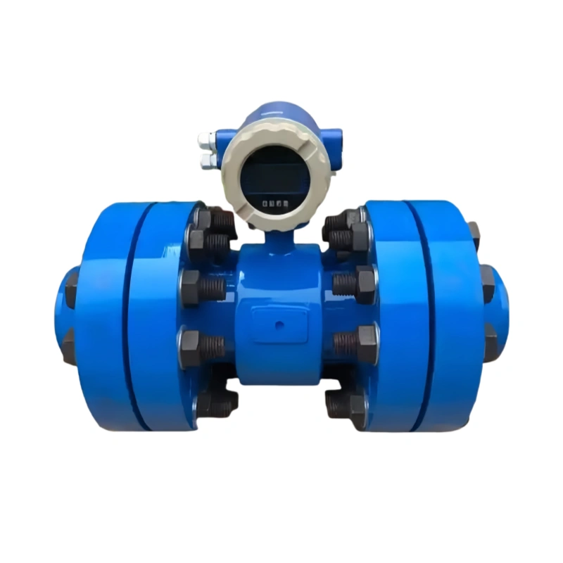
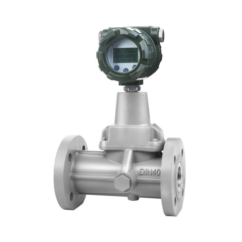
5. Vortex Flow Meter
Working Principle
Vortex flow meter measures gas flow by detecting the frequency of vortices generated when the fluid flows through a blunt body. Vortex flow meters are widely used and can measure a variety of fluids. Suitable for chemical, petrochemical and energy industries.
Advantages
- No moving parts, low maintenance cost.
- High accuracy. Wide range.
- Low pressure loss.
Disadvantages
- Not suitable for low Reynolds number measurements.
- Not suitable for high or low viscosity.
- Requires sufficient straight pipe section.
- Low instrument factor (compared to turbine flowmeter).
Parameter comparison of different types of natural gas flow meters
Flow meter type | Working Principle | Accuracy | Turndown ratio | Pressure drop | Cost | Application |
Differential pressure flow meter | By measuring the pressure drop across an orifice. | Lower than some flow meters. 3% to 5%. | Limited turndown ratio. | Higher than some flow meters. | Generally lower than Coriolis force. | Custody transfer, industrial applications. |
Thermal mass flow meter | Measures mass flow based on heat transfer from a heating element. | Above average. 1% to 3%. | High turndown ratio is usually 100:1 and can be as high as 1000:1. | Low. | Cost-effective. | Industrial processes, energy management. |
Ultrasonic flow meter | Measures flow based on an ultrasonic signal. | 0.7% to 1%. | Medium. 50:1. | Low. | Expensive.
| Custody transfer, wastewater. |
Turbine flow meter | Measures velocity based on the rotation of a turbine rotor. | Very good, but depends on operating conditions. | Wider range than some flow meters. | Low. | Moderate.
| Custody transfer, industrial applications. |
Vortex flow meter | Measures velocity based on vortex shedding. | 0.7% to 2.5%. | Good. | Low. | High. | Industrial applications, steam, compressed air. |
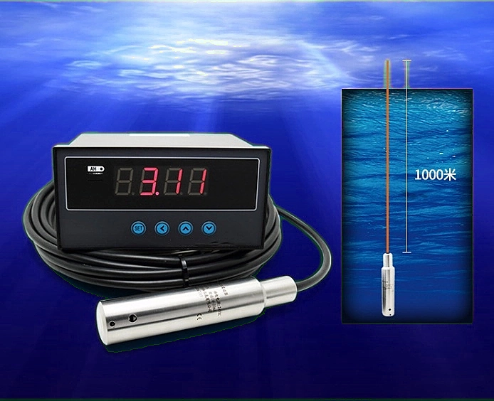
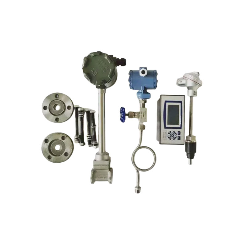
Key components
The following are some of the key components of a natural gas flow meter. These components work together to measure gas flow.
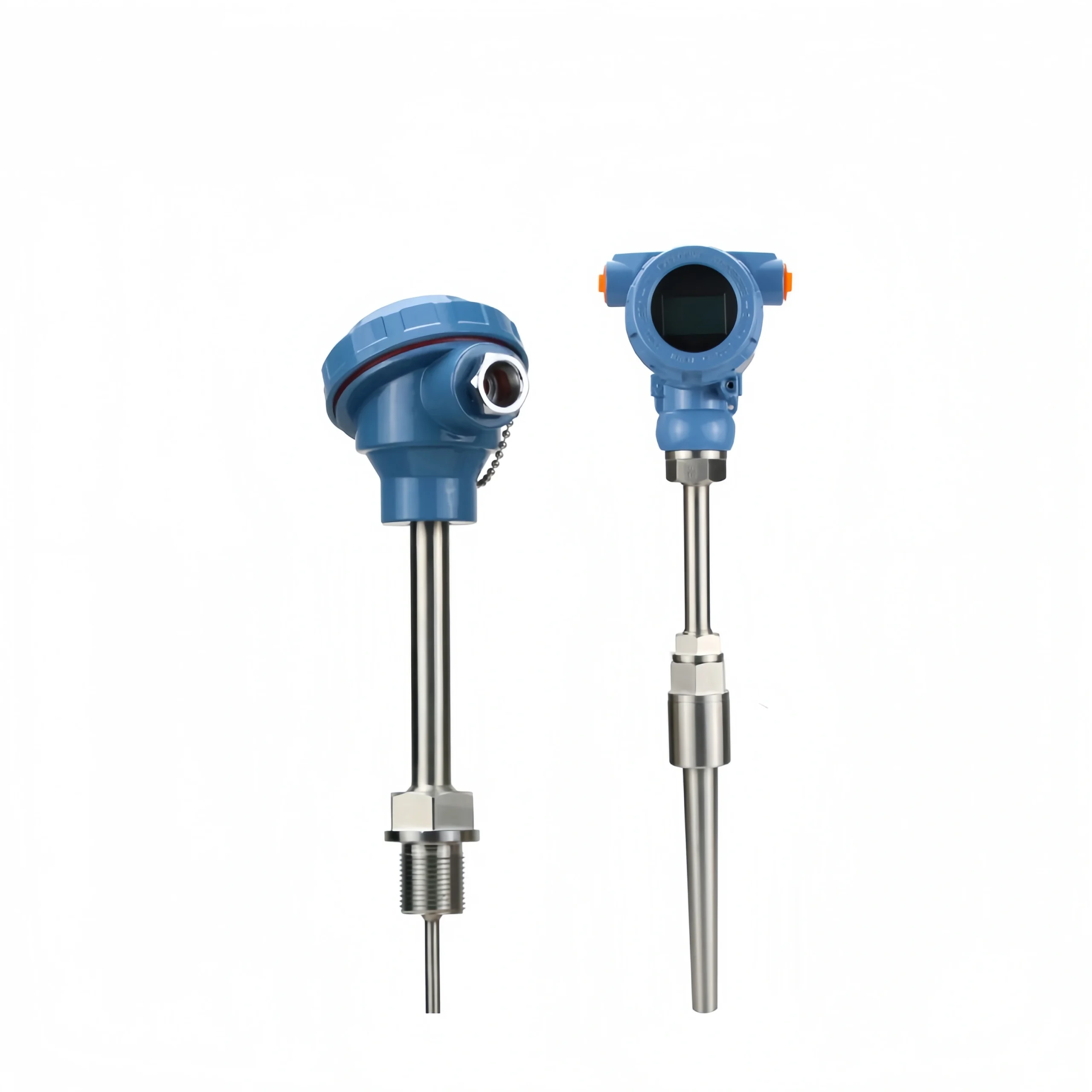
Electronic sensor: Used to detect flow and other characteristics of natural gas.
Transmitter: Converts sensor signals into a usable form.
Mechanical components (some meters): Some meters, such as turbine flow meters, rely on the movement of mechanical parts such as rotors to measure flow.
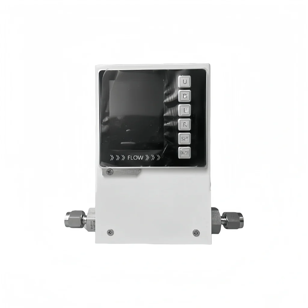
Display/output interface: Allows the user to visualize measurement data. For example, flow rate, total flow, and gas temperature.
Processing unit: Calculates flow based on the raw data provided by the sensor.
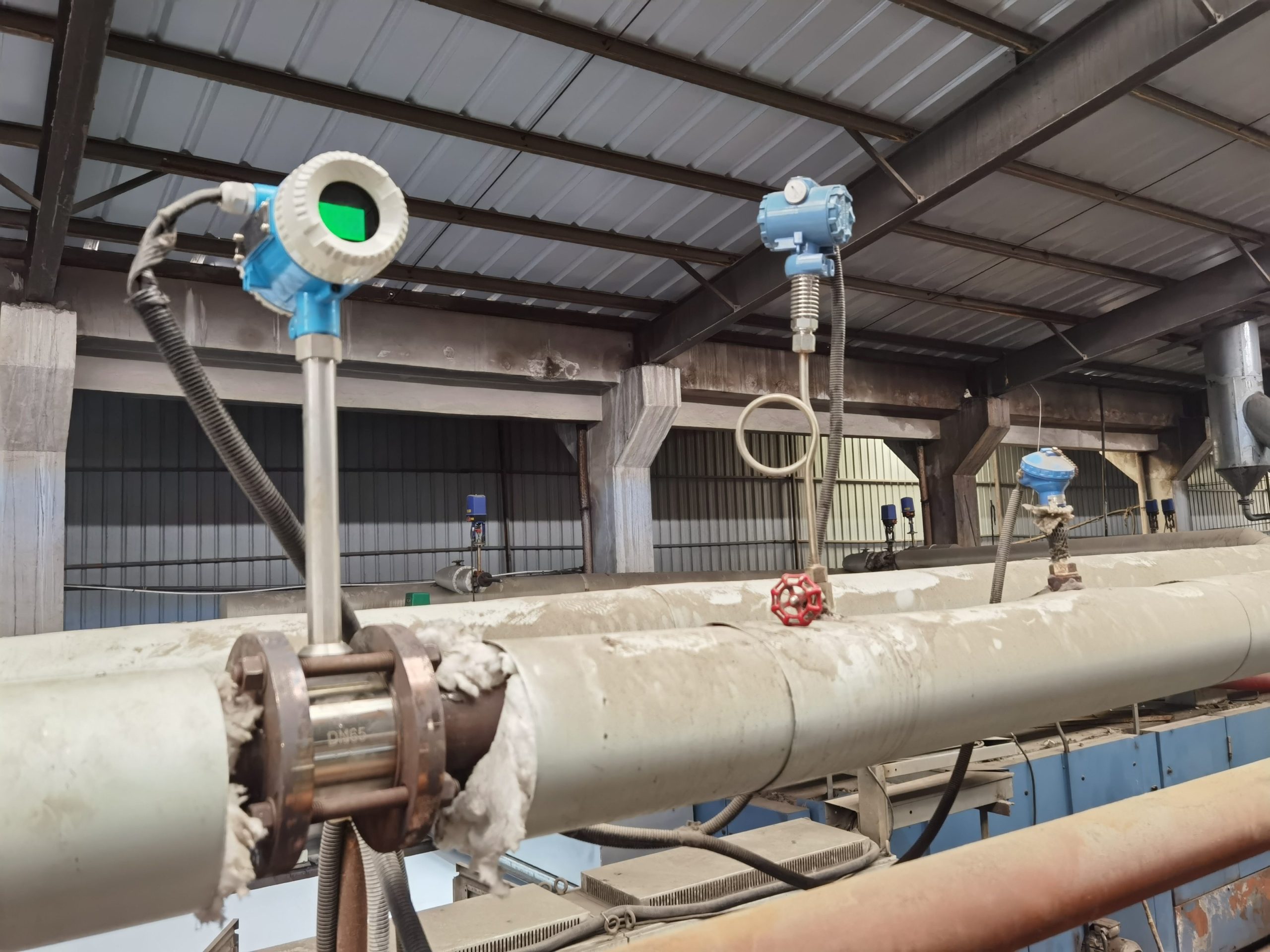
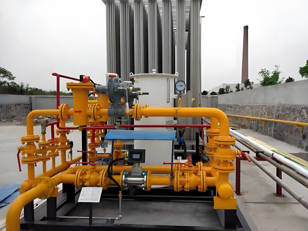
Applications of natural gas flow meters
Natural gas flow meter is an important instrument used to measure pipeline natural gas flow, playing a vital role in various industries.
- Energy distribution
- Process control
- Regulatory compliance
- Energy efficiency and auditing
- Power plants
- Oil and gas industry
Natural gas flow measurement is essential for industries that use natural gas and perform energy measurement and other processes. It involves detecting the volume or mass of gas using various flow meters.
A natural gas flow meter is a precision device used to measure the flow of natural gas in a pipeline. Sino-Inst offers a variety of flow meter products. Including differential pressure, thermal mass, ultrasonic, turbine, vortex flow meters. You can choose the right flow meter type based on your specific application.