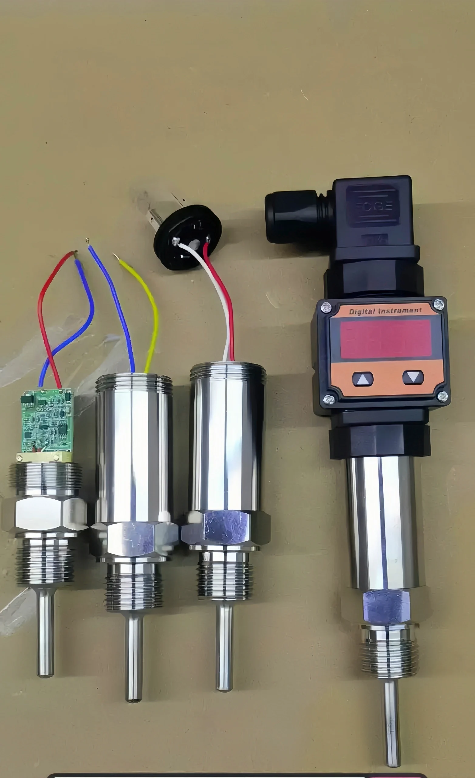
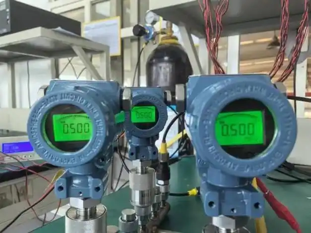
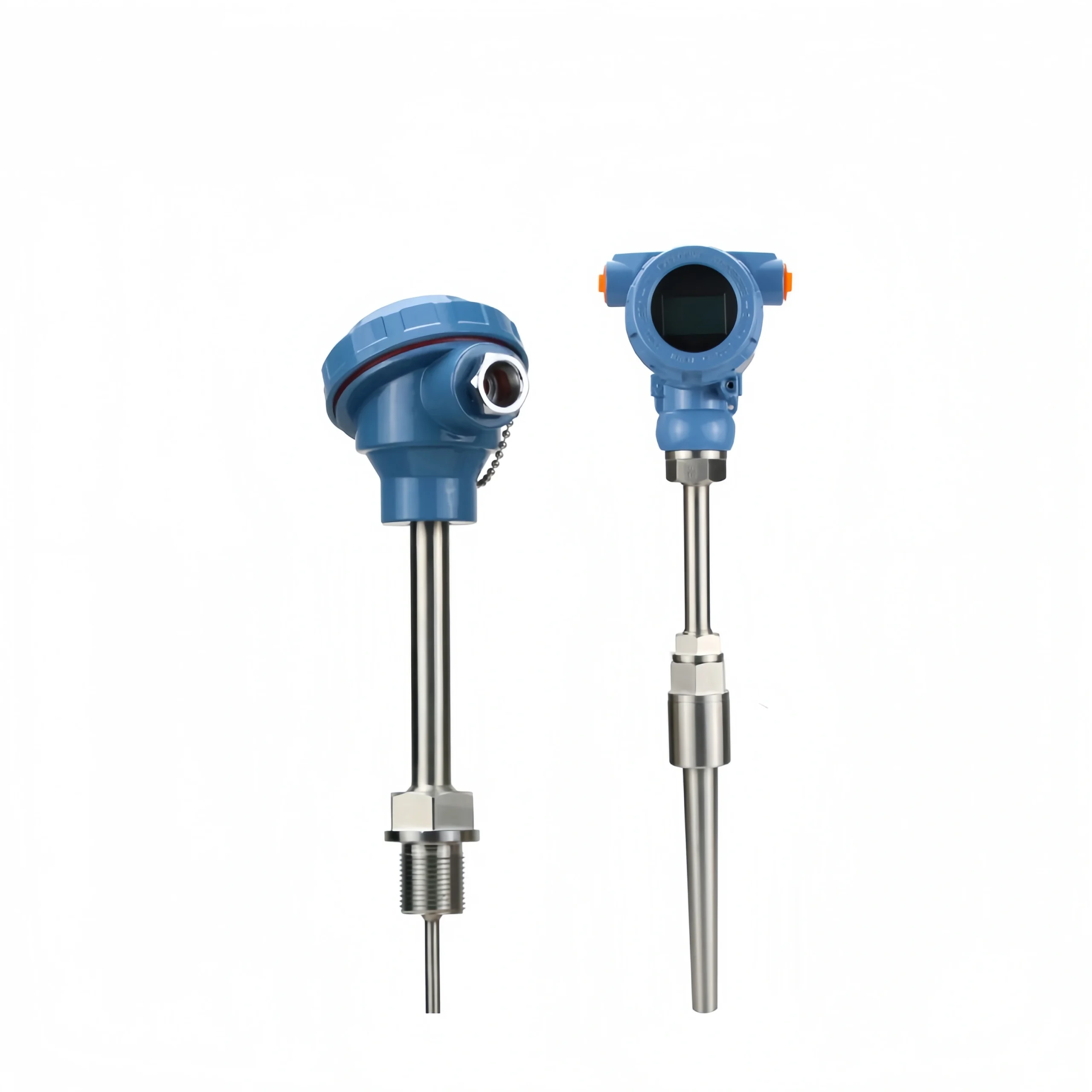
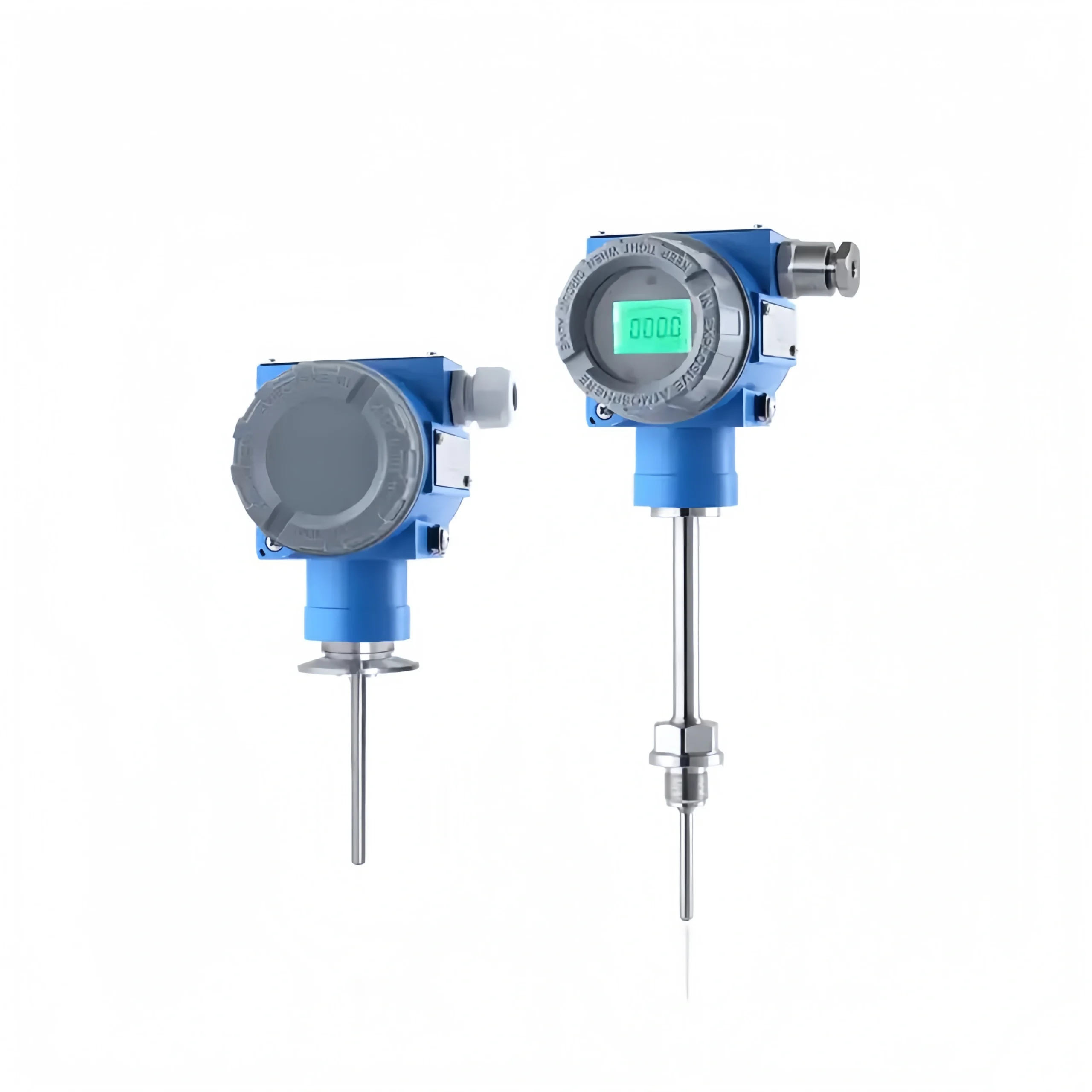
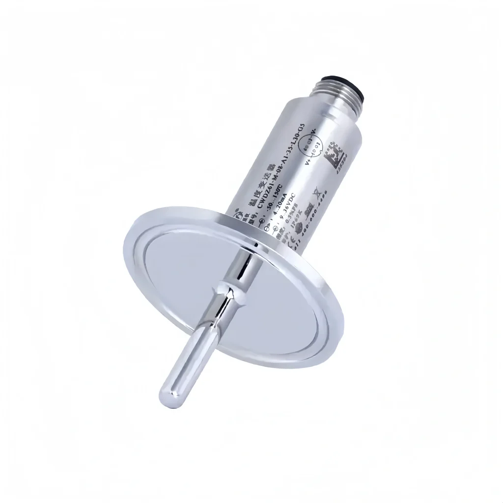
A temperature transmitter converts a temperature variable into a standardized output signal. It uses thermocouples and RTDs as temperature measuring elements.
The output signal from the temperature measuring element is sent to the transmitter module. After regulator filtering, operational amplification, non-linear correction, V / I conversion, constant current, and reverse protection circuit processing. It is converted into a linear relationship with the temperature of the 4-20mA current signal, 0-5V / 0-10V voltage signal, and RS-485 digital signal output. It is mainly used for the measurement of industrial process temperature parameters.
Read More about: Temperature Sensor vs Temperature Transmitter
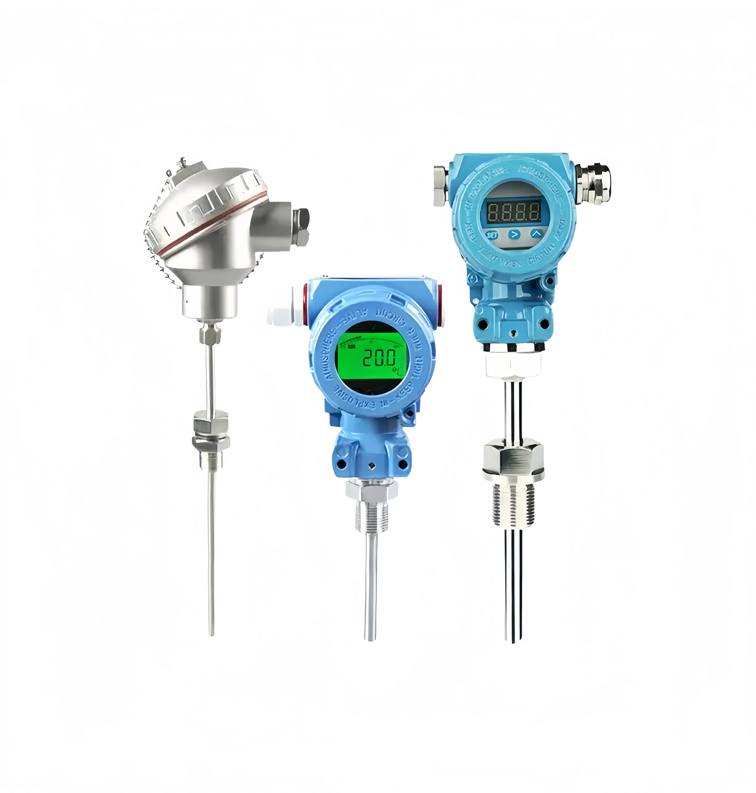
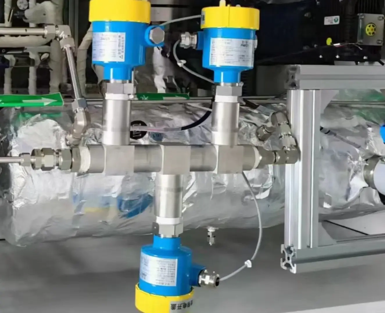
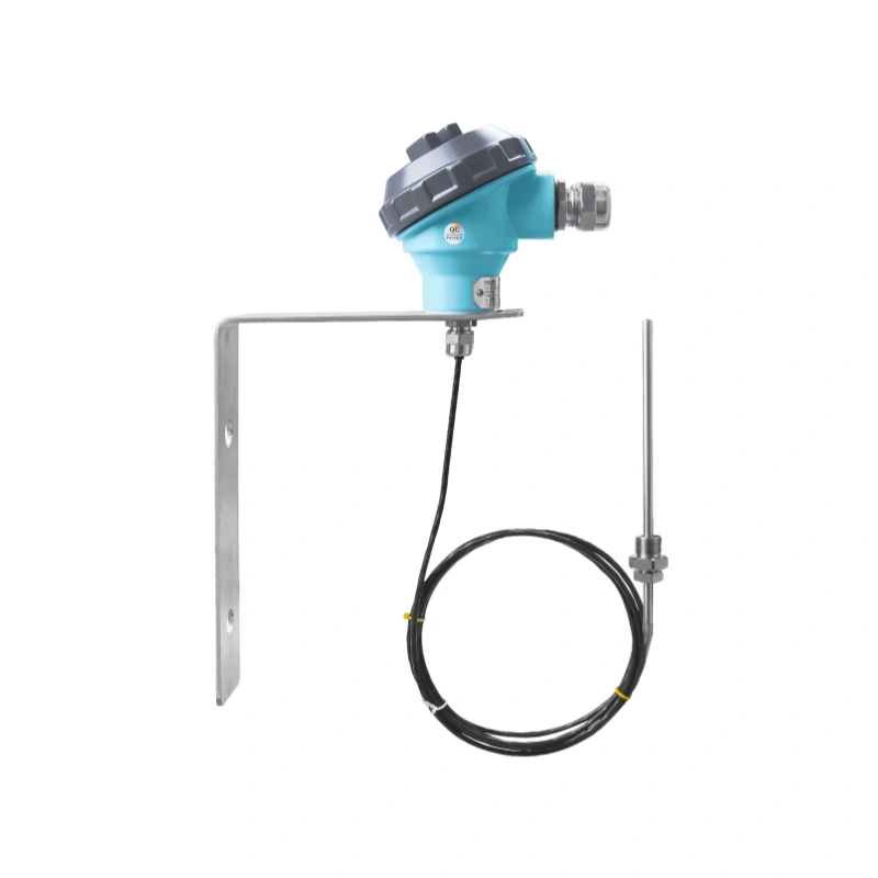
A temperature transmitter application is also very wide. It is mainly used in petroleum, chemical, chemical fiber, textile, rubber, building materials, electric power, metallurgy, medicine, food and other industrial fields for on-site temperature measurement process control.
High-temperature and high-pressure equipment includes boilers, heat exchangers, etc. A temperature transmitter can monitor the wall temperature of these devices in real time. To prevent over-temperature operation leading to equipment damage or even safety accidents. At the same time, for some flammable and explosive materials handling equipment, accurate temperature control is also a vital measure to ensure safe production.
Read More about: High Temperature Pressure Transmitter Applications in 1200 °C


Temperature transmitters are available in a variety of output forms. Different output forms have different characteristics. The following is a detailed description.
Analog Signal:
The most basic output signal of a temperature transmitter is an analog signal. Analog signals are divided into current signals and voltage signals.
4-20mA current signal in the industrial field is widely used, is one of the common temperature transmitter output signals. The signal indicates the lower limit of the measurement range with 4mA and the upper limit with 20mA. The current signal is not easily affected by wire resistance and external interference in the transmission process. It has strong anti-interference ability. It is suitable for long-distance transmission, about 200 meters.
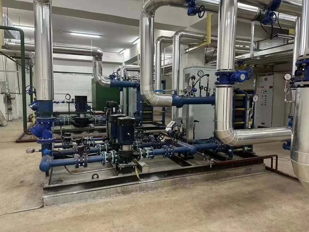
For example, in large-scale thermal power plants, temperature transmitters are installed on boilers, turbines and other equipment. The temperature data of the equipment is transmitted to the central control room, which is far away, through a 4-20mA current signal. To ensure that the control system can obtain accurate temperature information in real time.
0-5V Voltage Signal: The 0-5V voltage signal is also a common analog output signal. 0V corresponds to the lower limit of measurement. And 5V corresponds to the upper limit of measurement. Compared with the current signal, the voltage signal is affected by the wire resistance and contact resistance. And the voltage signal transmission distance is relatively short.
It is generally suitable for short-distance transmission scenarios. In some small automation control systems or laboratory equipment, due to the close distance between the equipment. A 0-5V voltage signal can meet the signal transmission requirements. And its cost is relatively low, and it is easy to realize.
A 0-10V voltage signal is also more commonly used. 0V represents the lower limit of measurement. 10V represents the upper limit of measurement. This signal has certain advantages in some occasions that require high measurement accuracy. However, it is transmitted over a much shorter distance. In high-precision temperature measurement systems, such as those used in the temperature control of semiconductor manufacturing equipment. A 0-10V voltage signal can provide a more accurate signal resolution. To meet the strict requirements of the production process for the accuracy of temperature measurement.
Digital signals:
A little more advanced signal output from a temperature transmitter is a digital signal. Digital signals are more versatile and costly. Digital signals include HART, Modbus and Profibus-PA, which are described in detail below.
The HART is a communication protocol that superimposes digital signals on analog signals. Temperature transmitters using the HART protocol can not only output 4-20mA analog signals. It also realizes two-way digital communication. Through the HART, the operator can remotely access the temperature transmitter’s measured values, device status, and calibration information. HART also provides remote configuration and diagnosis of the device.
Modbus is a widely used serial communication protocol. It supports a variety of electrical interfaces such as RS-232 and RS-485. Temperature transmitters using the Modbus protocol can easily communicate with various types of control systems that support the Modbus protocol. The protocol is simple to use and highly compatible. Among them, RS-485 is capable of transmitting up to a long distance of 2000 meters. And RS-485 also guarantees accuracy.
Profibus-PA is a fieldbus protocol designed for process automation with intrinsic safety for hazardous areas. Profibus-PA is able to realize high-speed and reliable digital communication. And it supports multiple devices to be connected to one bus at the same time. In industries such as chemical and petroleum, there is a risk of flammable and explosive production environments. Profibus-PA protocol temperature transmitters can ensure communication with control systems in hazardous environments.
In summary, the choice of which output signal needs to be based on the specific and demand to decide. If the application scenario requires long-distance transmission, strong anti-interference ability, and an easy interface with other devices, then it is suitable. Then a 4-20mA current signal may be a better choice. If the application scenario requires remote data transmission and advanced control features. Then a digital signal may be more appropriate.
We should also choose the right signal output based on back-end compatibility. For example, if the PLC system can only accept RS-485 signal input, then we can’t choose 4-20mA. Choosing a signal output is a complicated matter, so it is recommended to consult a professional technician when you are not sure.
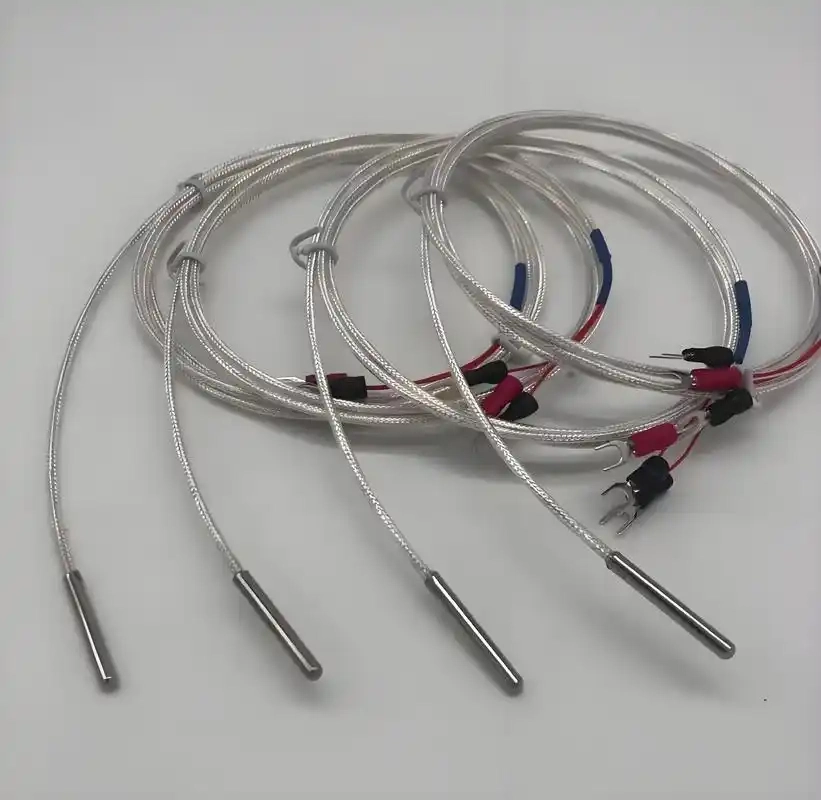
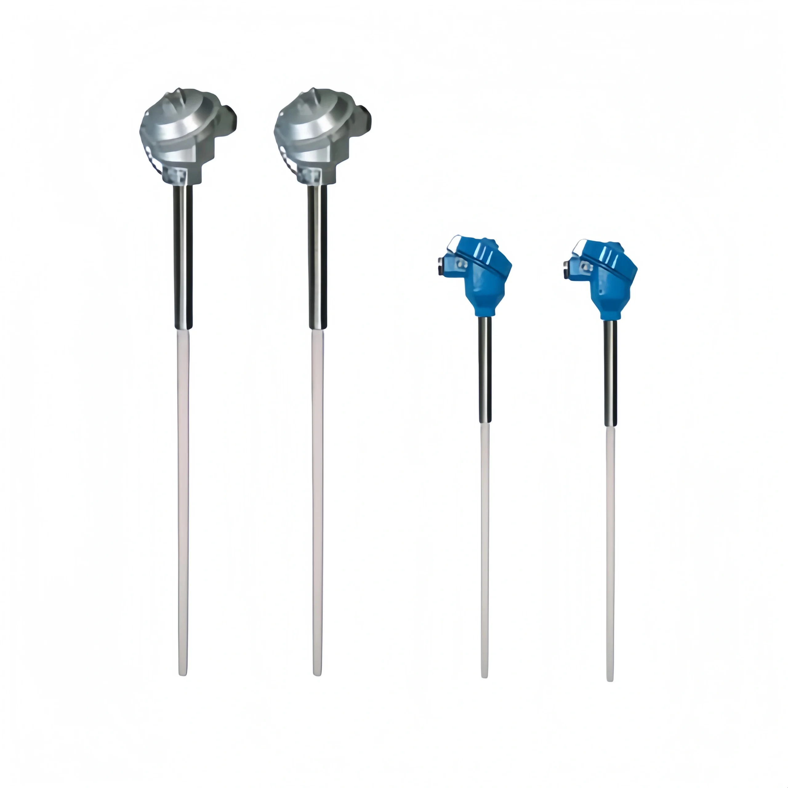
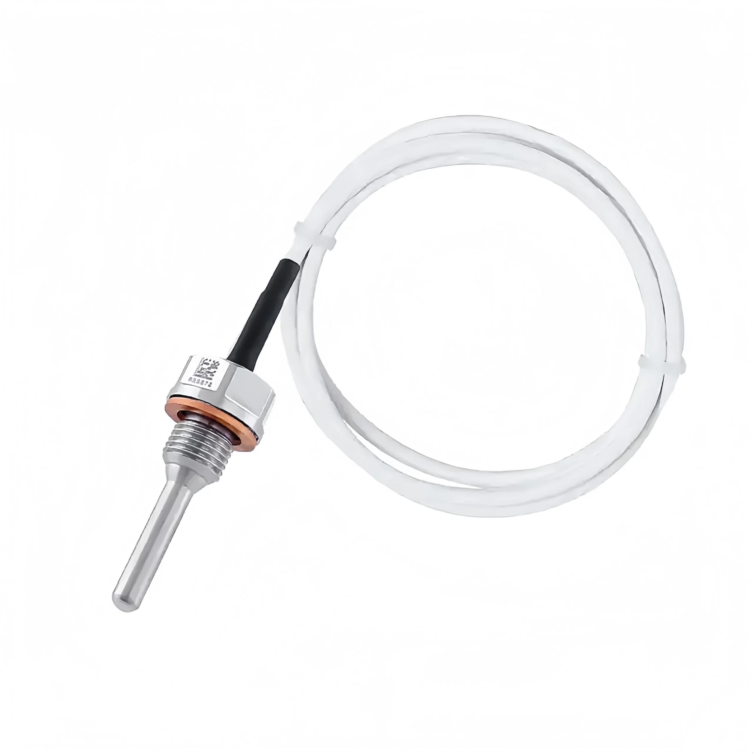
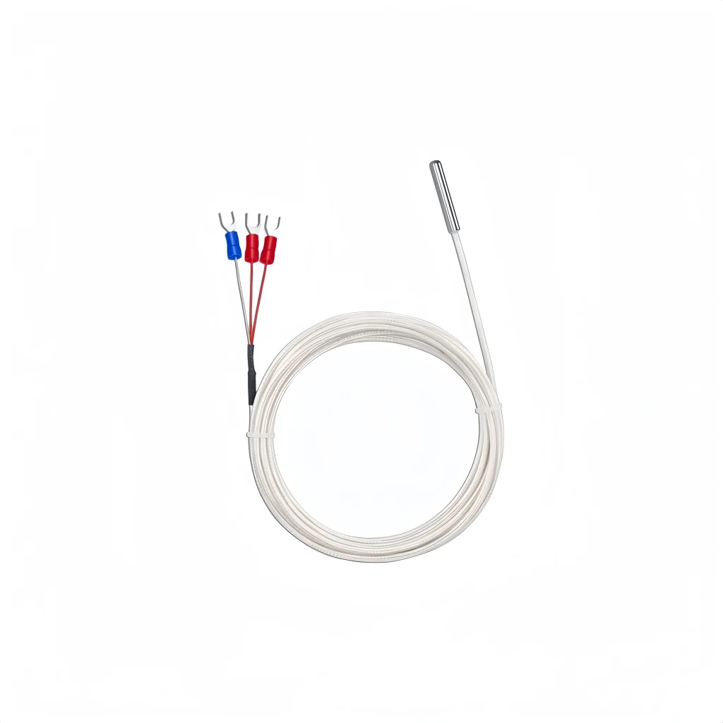
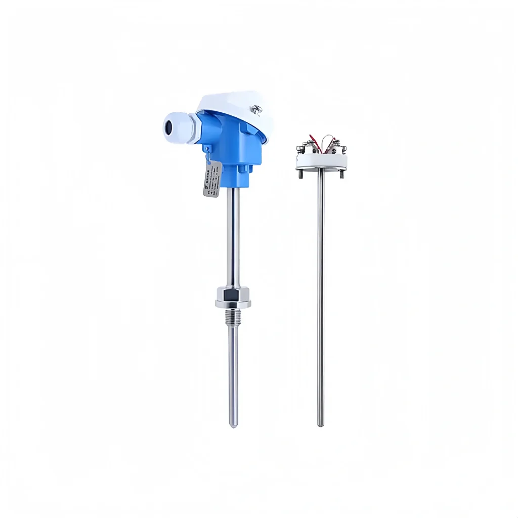
Since the signal output from an RTD or thermocouple temperature sensor is usually used when the output is close. Its signal strength and linearity are not a problem. But when the output distance is far away, the signal is very weak or non-linear. So it is necessary to use a temperature transmitter to convert the RTD or thermocouple signal to a standard signal. To facilitate the system’s unified processing.
The temperature transmitter’s built-in signal conditioning circuit can compensate for the sensor’s nonlinear error, improving the overall measurement and transmission accuracy. At the same time, the output of standardized signals can effectively reduce the complexity of the subsequent circuit and compatibility issues. The following is the wiring diagram of the temperature transmitter module:
The temperature transmitter processes the signal in the following ways. The temperature transmitter will amplify the pressure transmitter, cold end compensation, linearization, and low-pass filtering process. And it finally outputs a standard analog signal or digital signal.
The raw signal (mV voltage or resistance change) generated by the sensor is so weak that the electronic circuitry inside the transmitter first linearly amplifies it to a standard level suitable for subsequent processing.
Thermocouples have cold-end compensation. The thermal potential generated by a thermocouple is a function of the temperature difference between the hot end and the cold end. In order to obtain an accurately measured temperature, the transmitter needs to measure the actual temperature of its cold end. Based on this temperature, the thermopotential to be compensated is calculated and superimposed on the original signal. Thus, it eliminates the error caused by the temperature change at the cold end.
There is a degree of nonlinearity between temperature and resistance or thermocouple. The transmitter usually has a linearization curve stored internally for the corresponding sensor type. Linearizes the amplified/compensated signal so that it directly represents the measured temperature value.
Temperature transmitters also have low-pass filtering. This removes high-frequency noise (electromagnetic interference, vibration interference, etc.) that may be contained in the signal and improves signal stability and accuracy.