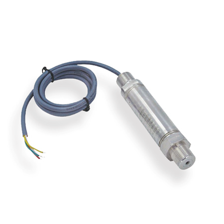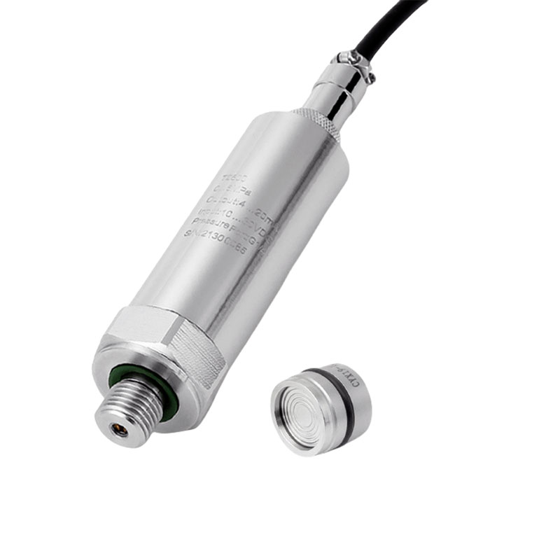

Integrated Temperature Transmitter Wiring and Calibration:
The transmitter system is connected as shown in the diagram. A 24VDC power supply is supplied to the transmitter via a shielded cable. Connect “V+” to the positive terminal of the 24VDC supply, and “V-” to the negative terminal, outputting 4-20mA. Connect the transmitter to a standard signal source (resistance box or millivoltmeter).
When the signal source provides zero and full-scale signals. It repeatedly adjusts the zero and full-scale potentiometers to precisely adjust the span.
“Z” represents the zero adjustment potentiometer
“S” represents the full-scale adjustment potentiometer (all potentiometers are factory-calibrated).
During use, errors due to factors such as line resistance and ambient temperature occur. Simply fine-tune the zero potentiometer “Z” to correct them. This calibration method can also be used to correct system errors.
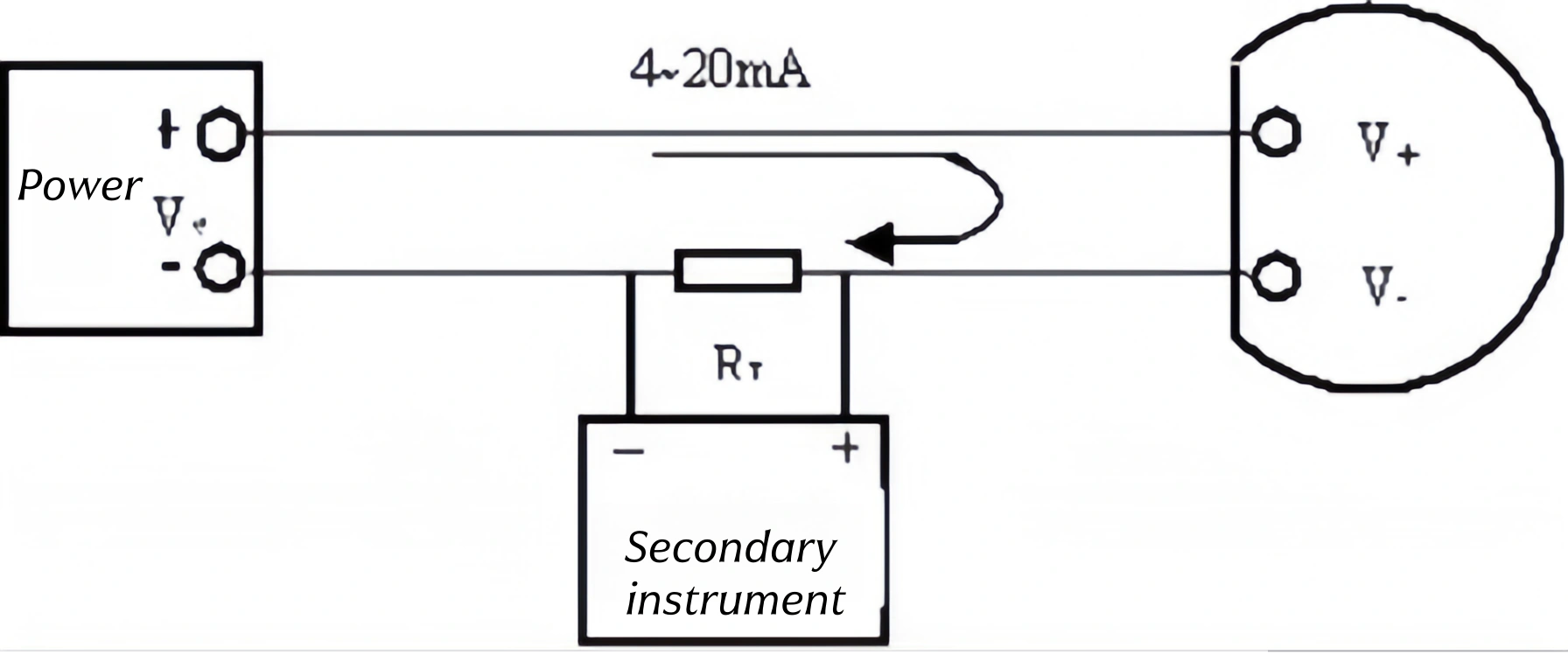
Note: Typically, the power supply voltage Vs is 24V, and the load resistor RL is 250Ω. This means that when a current of 4-20mA flows through the loop, the voltage drop across RL is 1-5V. If different values for Vs and RL are used, the RL value must not exceed the value calculated using the formula RL = (Vs – 13)/0.02.
What affects temperature transmitter accuracy?
After selecting a temperature transmitter, the wiring method used during field use can also affect the transmitter’s measurement accuracy.
For example, RTD sensors can be connected to the transmitter using two-wire, three-wire, or four-wire wiring. The two-wire connection includes the wire resistance in the RTD value, which can increase measurement error. Three-wire and four-wire wiring eliminates this problem by eliminating wire resistance.
For another example, for thermocouple temperature sensors, compensation wire of the appropriate material must be used for the field connection to the transmitter. This is vital to avoiding errors caused by differences between the actual cold-end temperature and the cold-end temperature measured by the transmitter.
It is important to note that whether the cold end compensation element in a thermocouple temperature transmitter is internal or external also affects accuracy.
Site environmental factors can also affect the measurement accuracy of a temperature transmitter. For example, temperature, humidity, electromagnetic environment, vibration, and power supply all have a certain impact on accuracy. The temperature transmitter should be installed and used within its specified environmental conditions. To ensure that the required measurement accuracy is met.

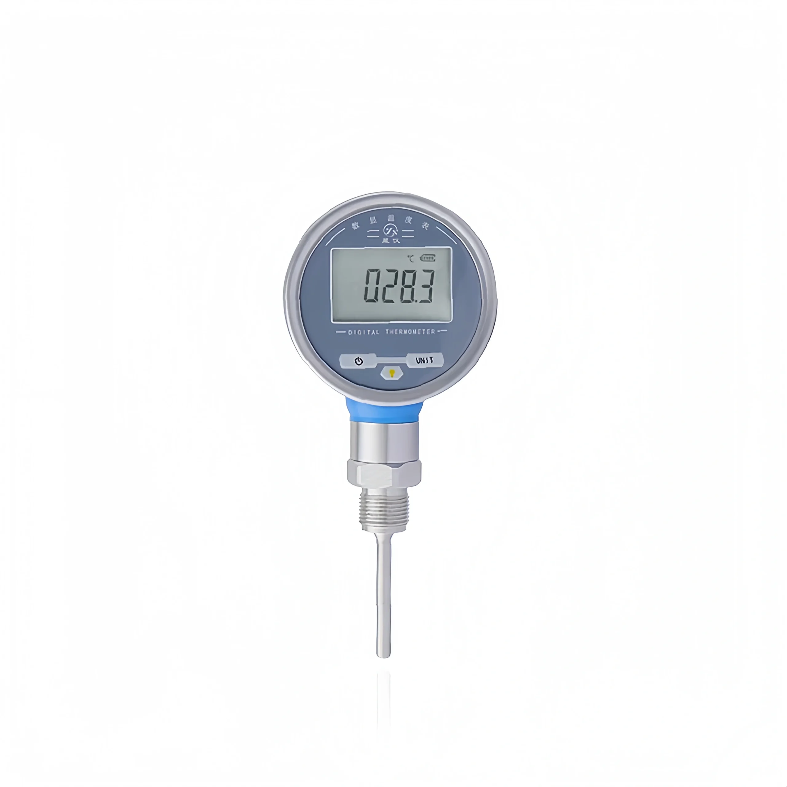
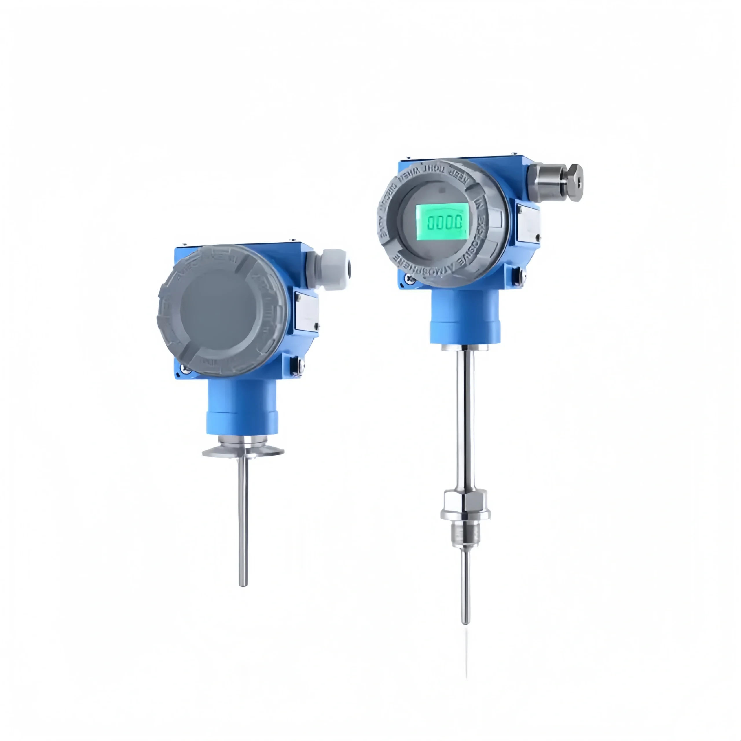
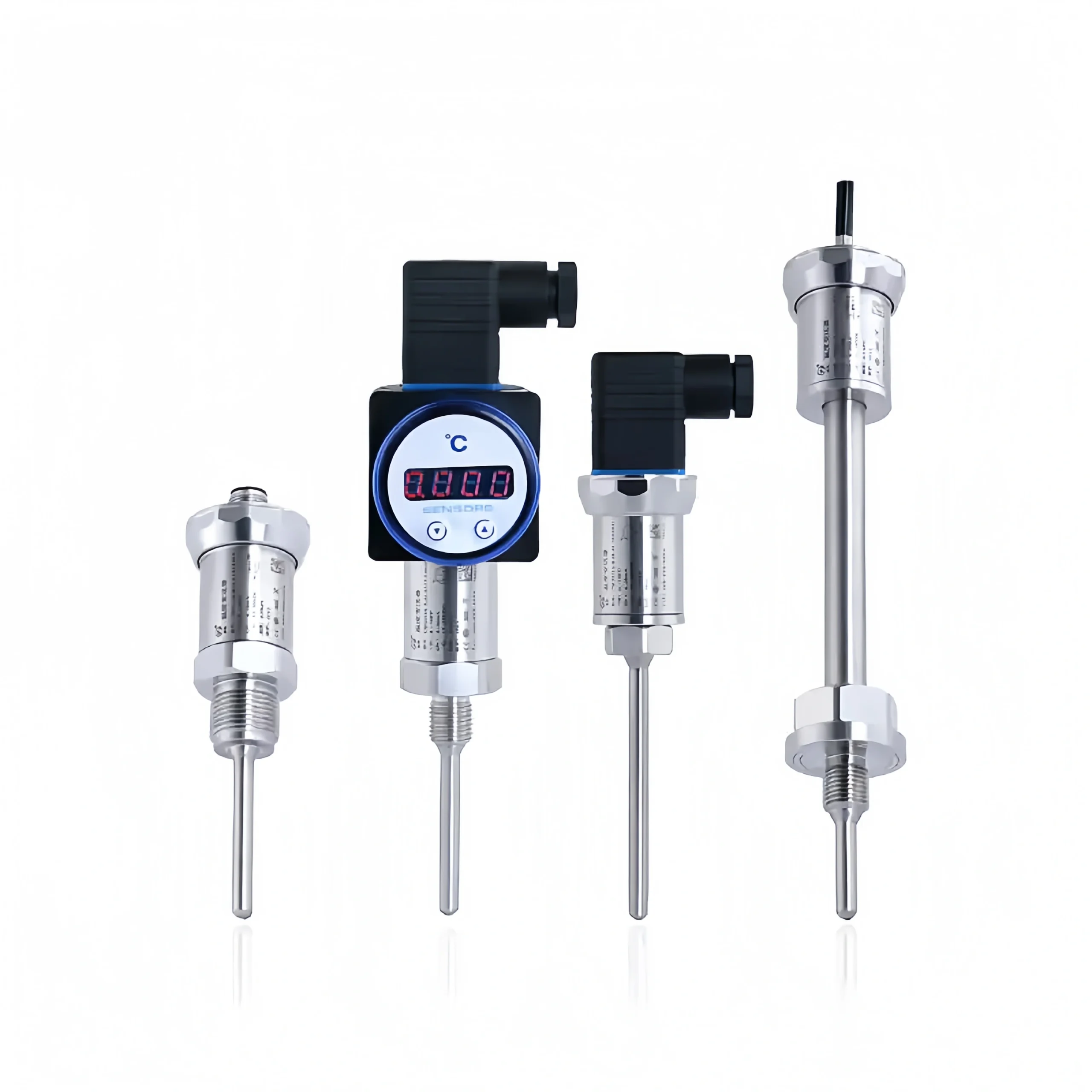
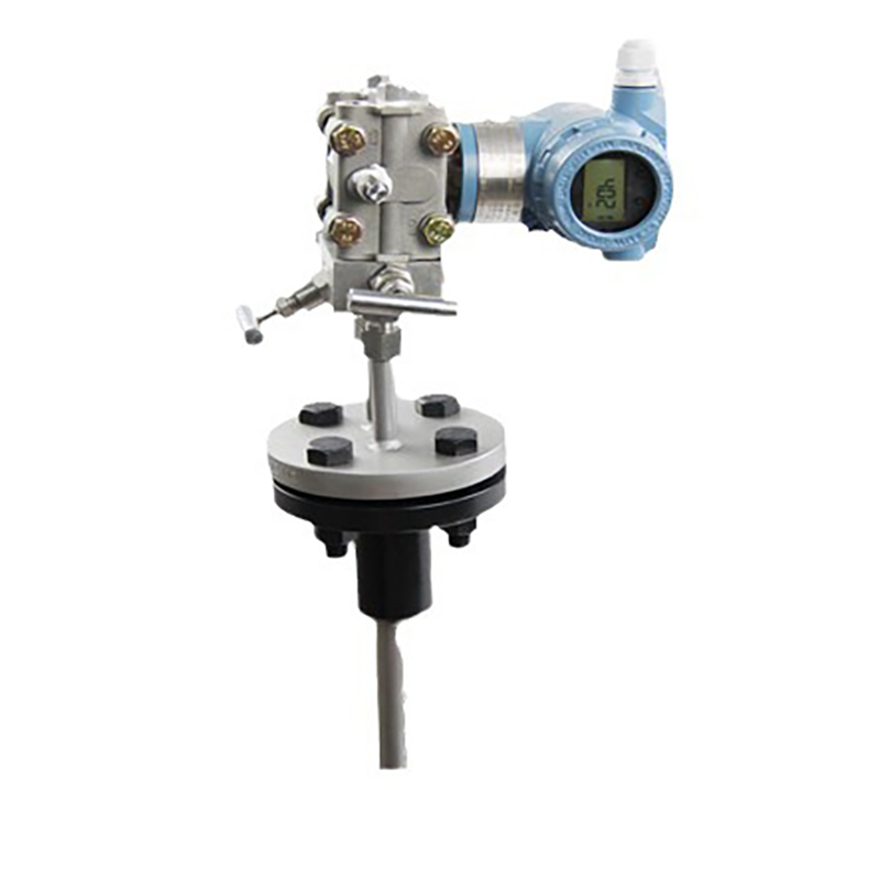
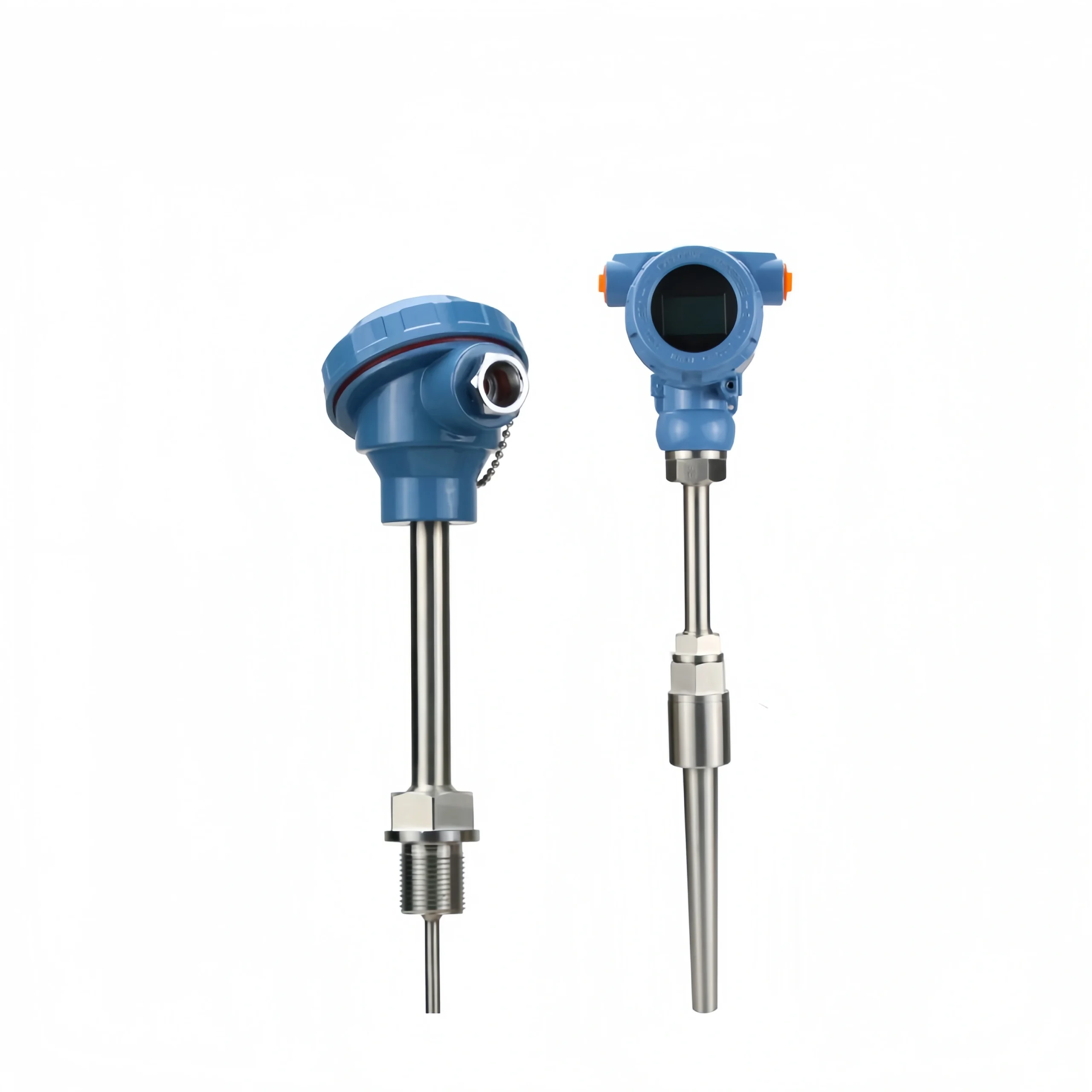
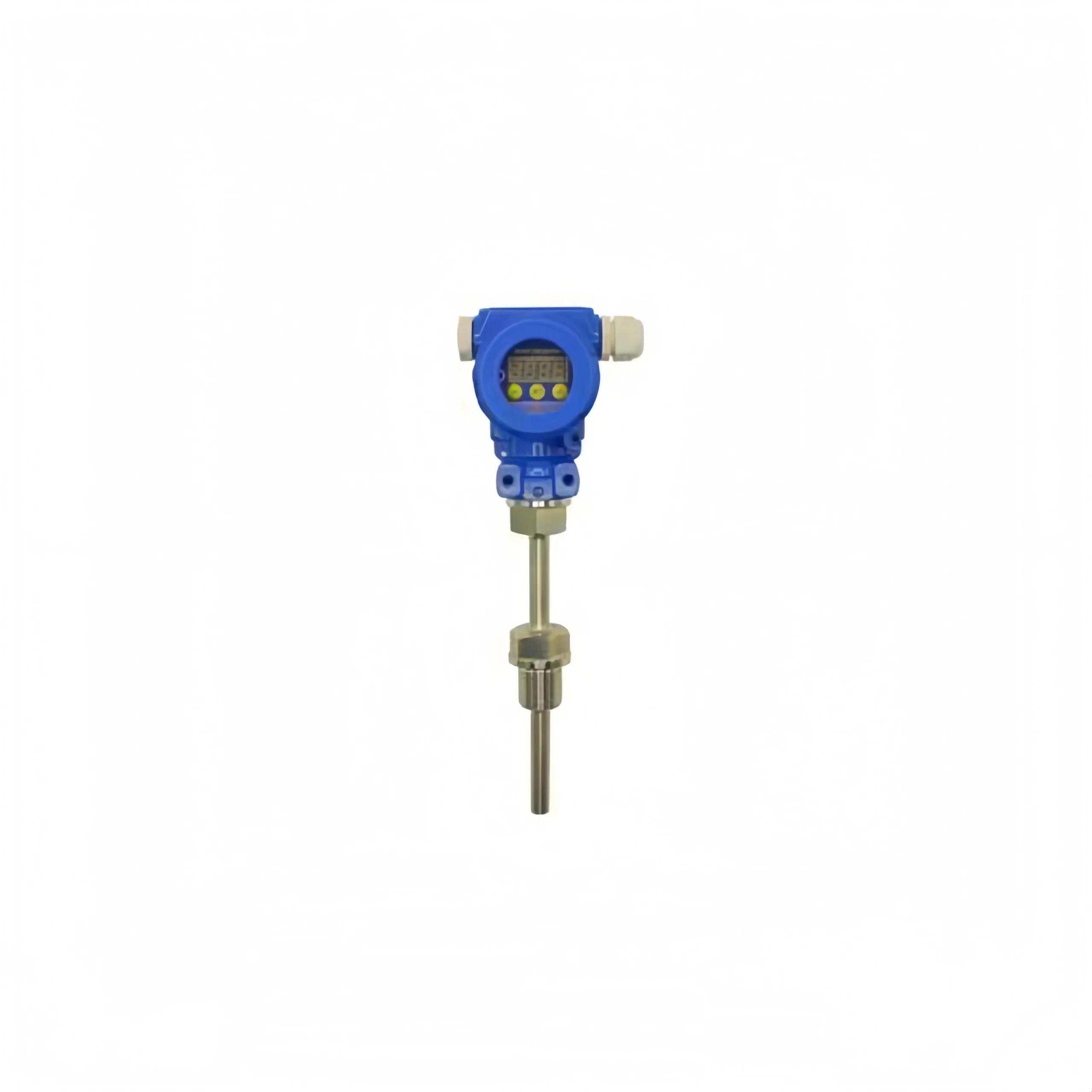
Is there a way to monitor temperature remotely?
Sino-Inst supplies remote temperature transmitters. They can monitor temperature remotely, making it convenient for users to record data.