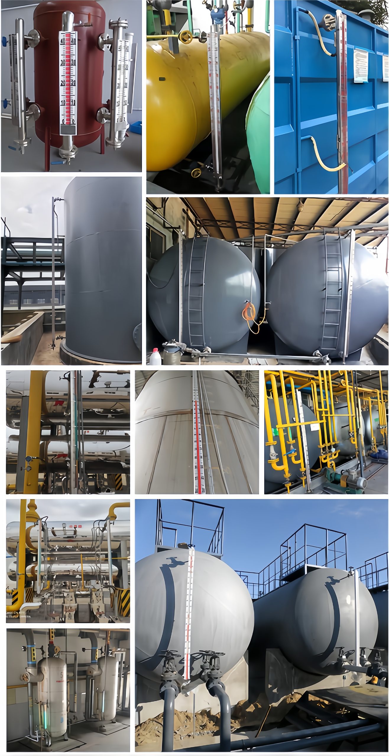
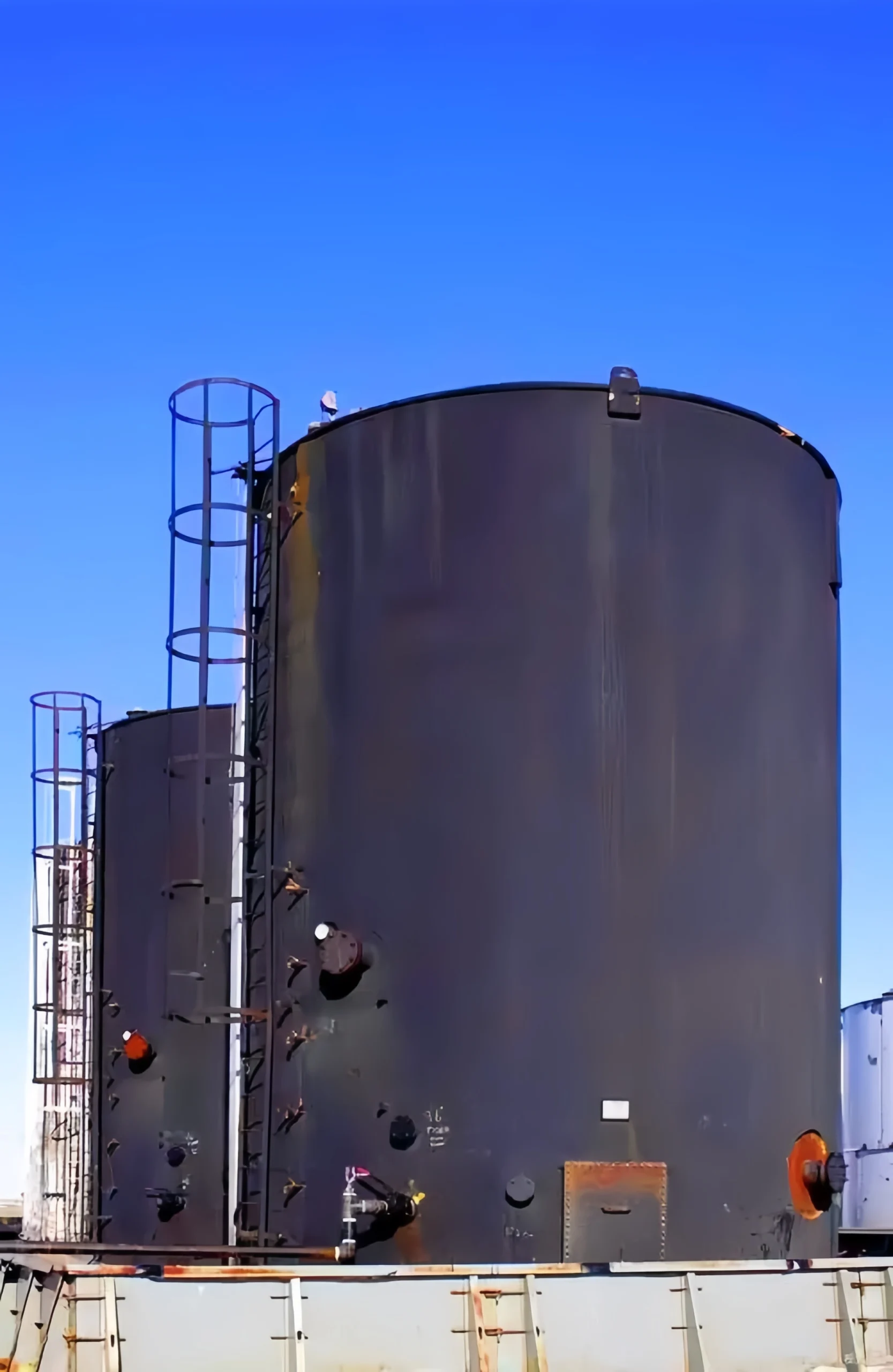
Generally speaking, fuel is a fuel used to generate energy. It is primarily derived from petroleum. The most common fuels include gasoline, diesel, jet fuel, and fuel oil.
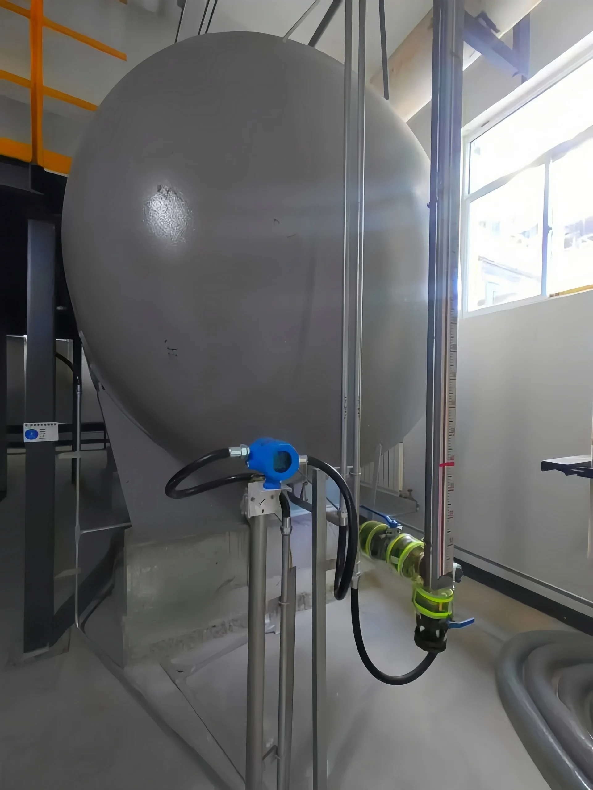
Due to the unique characteristics of fuel storage tanks, measuring their level presents several challenges.
Vapor interference:
During the measurement process in fuel tanks, vapor generated due to pressure, temperature, and transportation can interfere with the level sensor’s measurement results. Technical measures are needed to eliminate and minimize this interference.
Temperature changes:
The density of fuel changes with temperature, so the impact of temperature must be considered when measuring the level of fuel tanks.
Dynamic level: Due to the use of fuel tanks, the fuel level often fluctuates and changes.
Fuel level measurement is crucial in industrial processes. It can improve energy efficiency. A fuel level sensor is an instrument used to measure fuel level. This article will focus on fuel level sensors.
Sino Inst can provide some level sensors to measure fuel level. Different level sensors are suitable for different operating conditions. If you are unsure how to choose a suitable fuel level sensor, please feel free to contact us. Our professional engineers will recommend a suitable measurement solution.
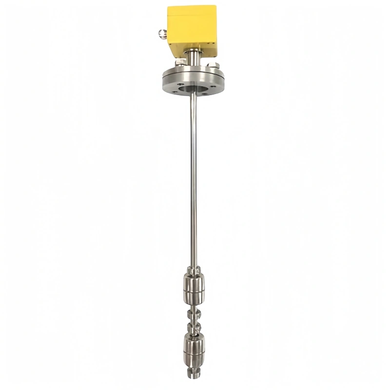
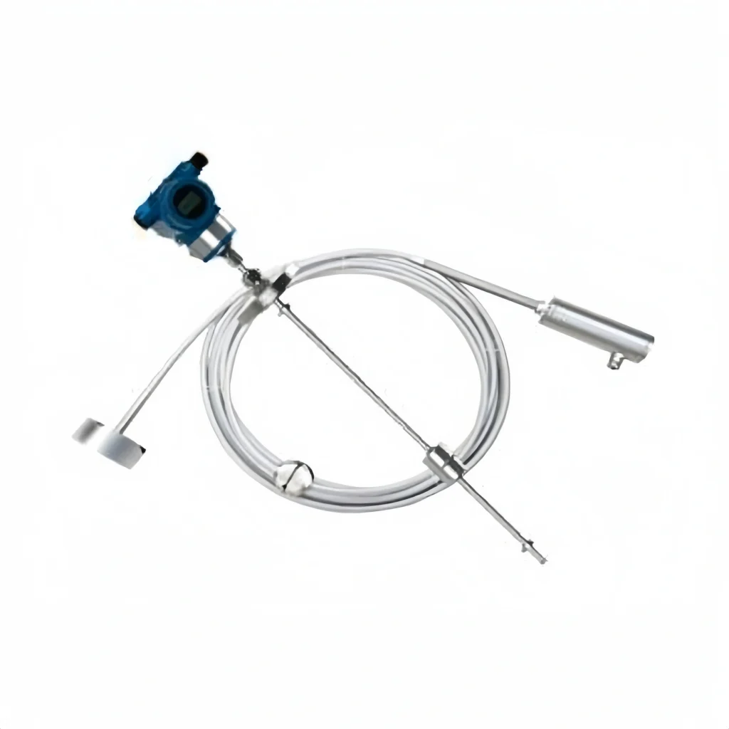
Float Level Sensor
Float level sensors are designed and manufactured based on the principles of buoyancy and static magnetic field. The position of a magnetic float (referred to as the float) in the measured medium is affected by buoyancy. Changes in the liquid level cause changes in the position of the magnetic float.
The interaction between the magnet in the float and the sensor causes the number of components connected in series to change, which in turn causes a change in the electrical quantity in the instrument’s circuit system. This change in the position of the magnetic float causes a change in the electrical quantity. By detecting this change in electrical quantity, the liquid level in the container is reflected.
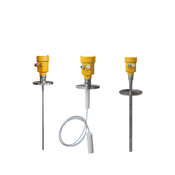
Radar Level Sensor
Radar level sensors are measuring instruments based on the time-travel principle. Radar waves travel at the speed of light, and the travel time is converted into a level signal by electronic components. The probe emits a high-frequency pulse that travels along a cable probe. When the pulse strikes the material surface, it is reflected and received by a receiver within the instrument. It converts the distance signal into a level signal.
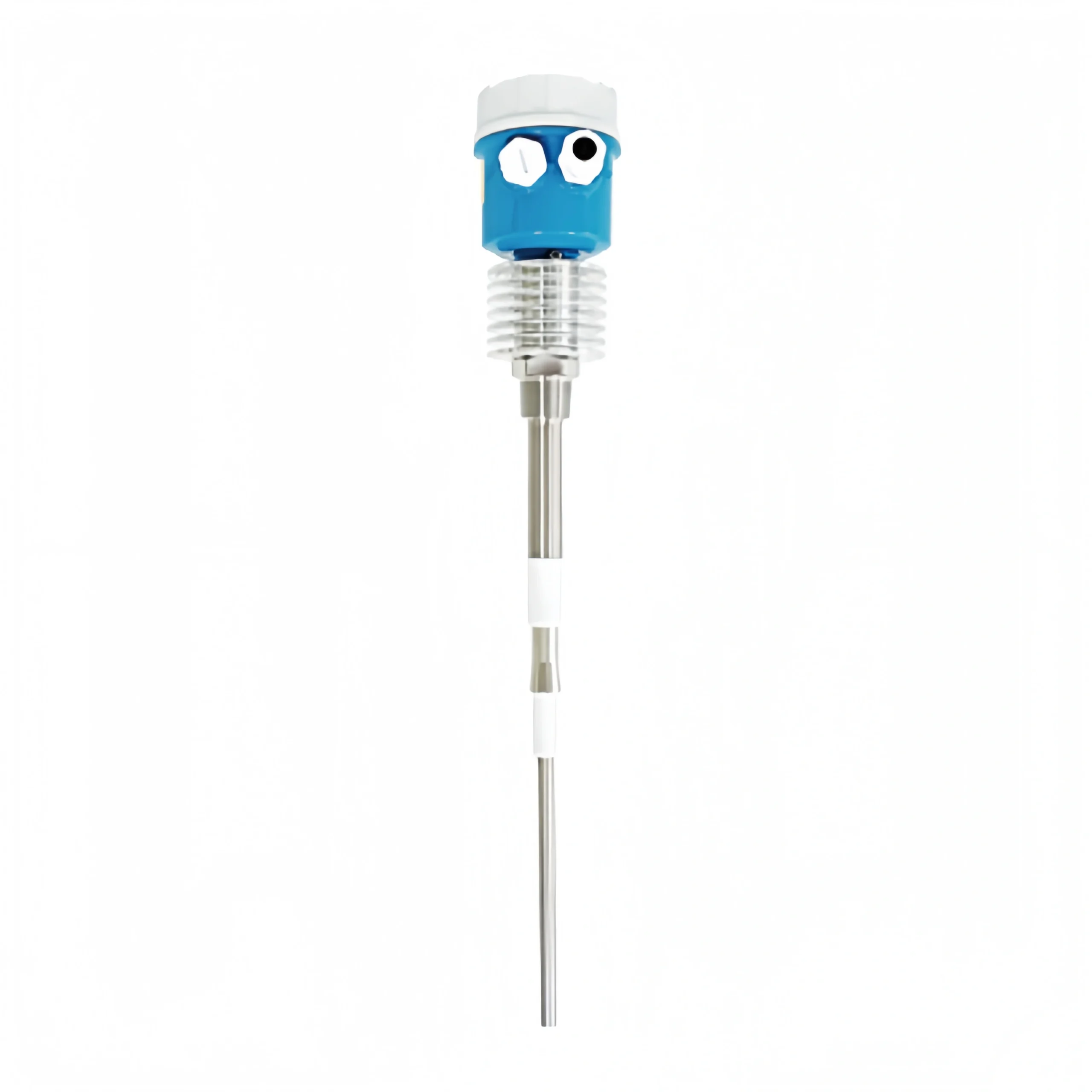
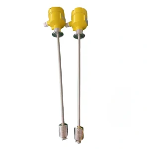
Tuning Fork Level Sensor
A tuning fork level sensor is a pair of piezoelectric crystals mounted on a sonic base that causes the sonic element to vibrate at a specific resonant frequency. When the sonic element comes into contact with the measured medium, the frequency and amplitude of the tuning fork change. These changes are detected. convert into a switching signal by intelligent circuitry.
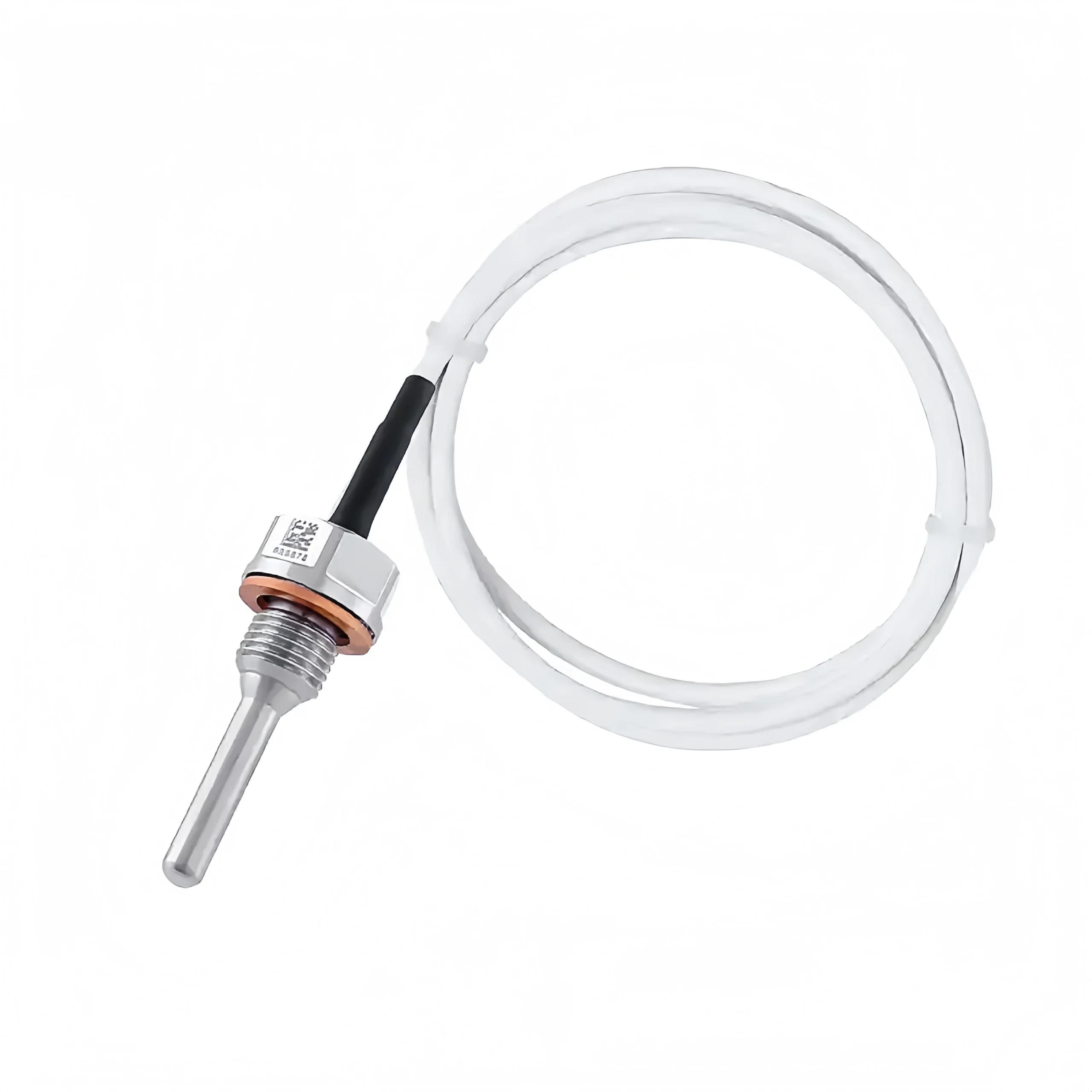
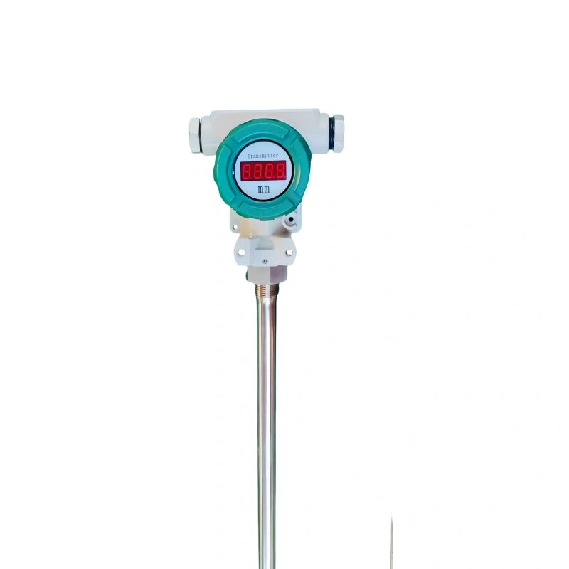
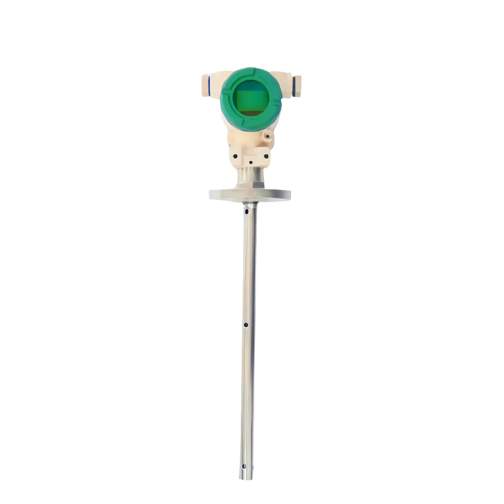
Capacitance Level Sensor
A capacitance level sensor uses changes in capacitance. Measure the height of a wavefront. A metal rod is inserted into a container of liquid, with the rod acting as one electrode and the container wall as the other. The medium between the two electrodes is the liquid and the gas above it.
Because the dielectric constant ε1 of the liquid differs from the dielectric constant ε2 at the liquid surface (e.g., ε1 > ε2), as the liquid level rises, the total dielectric constant between the two electrodes of the capacitance level sensor increases. Lead to an increase in capacitance. Conversely, as the liquid level drops, the ε value decreases, and the capacitance also decreases.
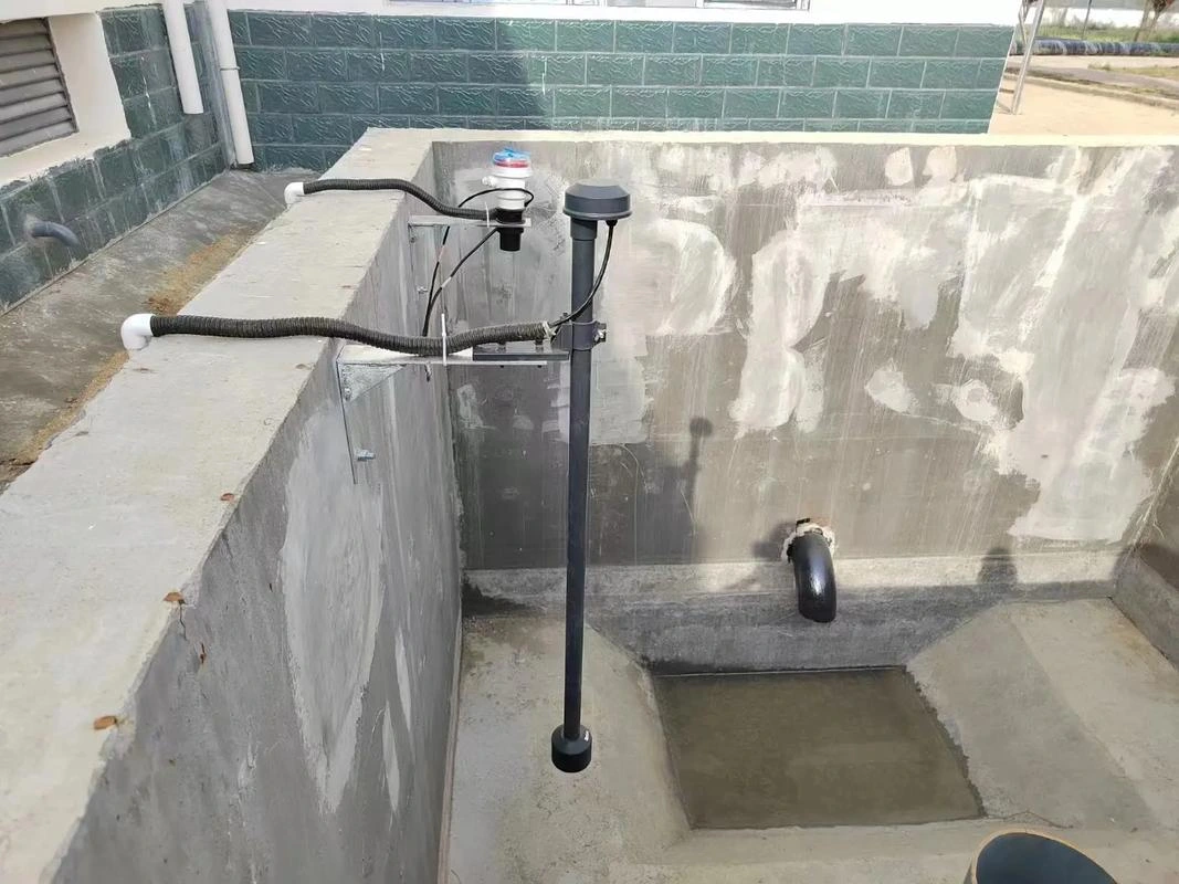
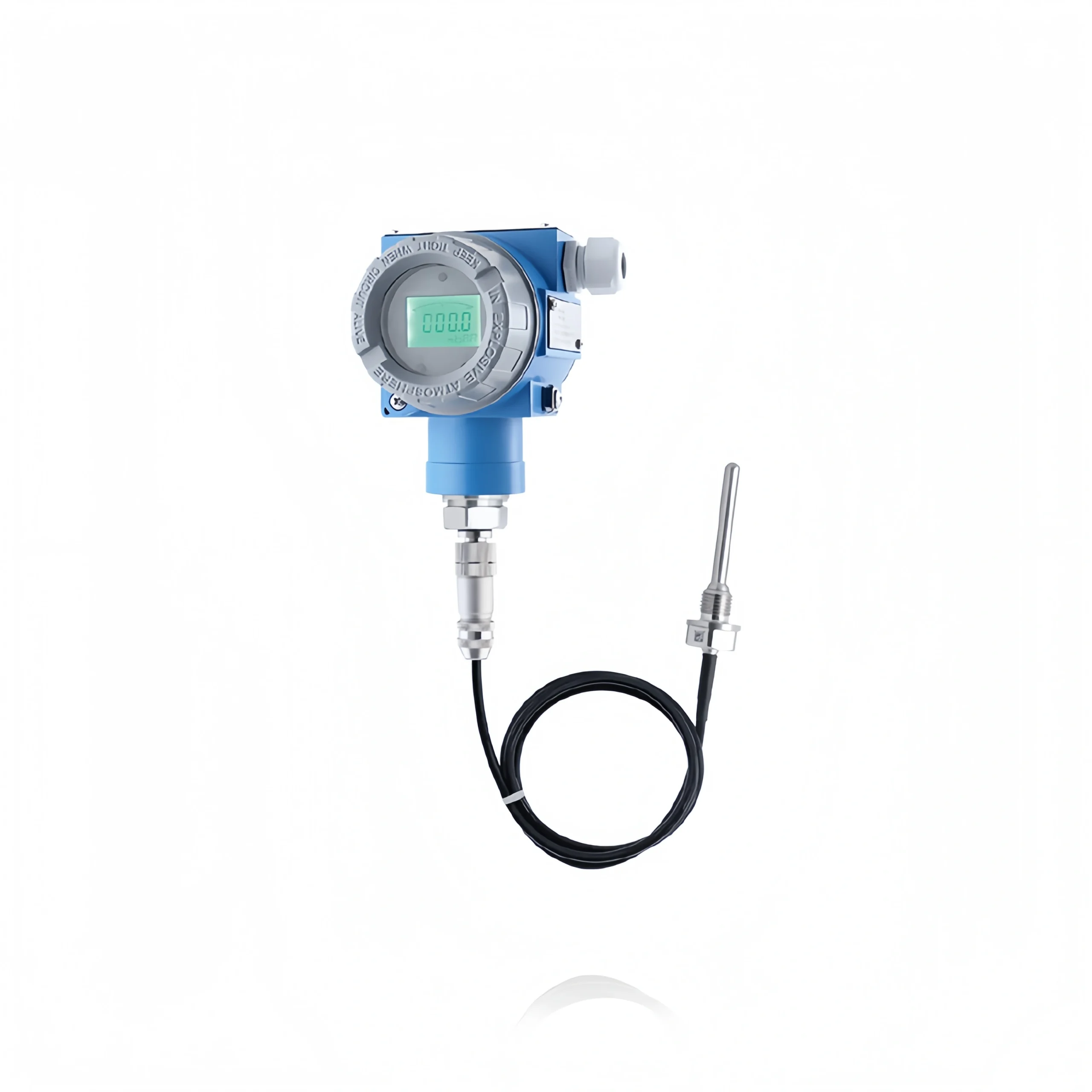
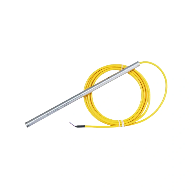
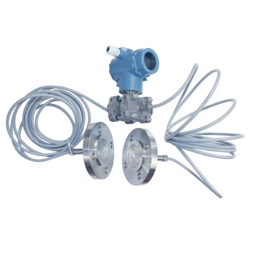
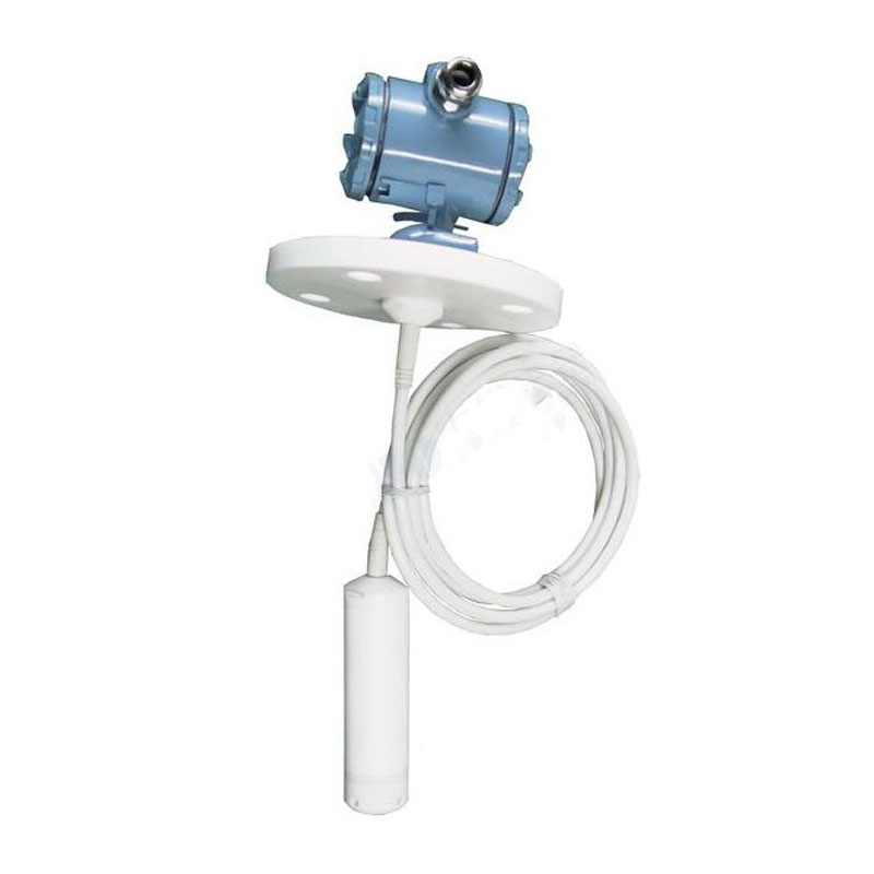
Hydrostatic Level Sensor
Hydrostatic level transmitters encapsulate a diffused silicone oil-filled core within a stainless steel housing. A front protective cap protects the sensor diaphragm and allows smooth liquid contact. The waterproof wiring is sealed to the housing, and a vent tube is connected to the outside world within the cable. The internal structure is designed to prevent condensation.
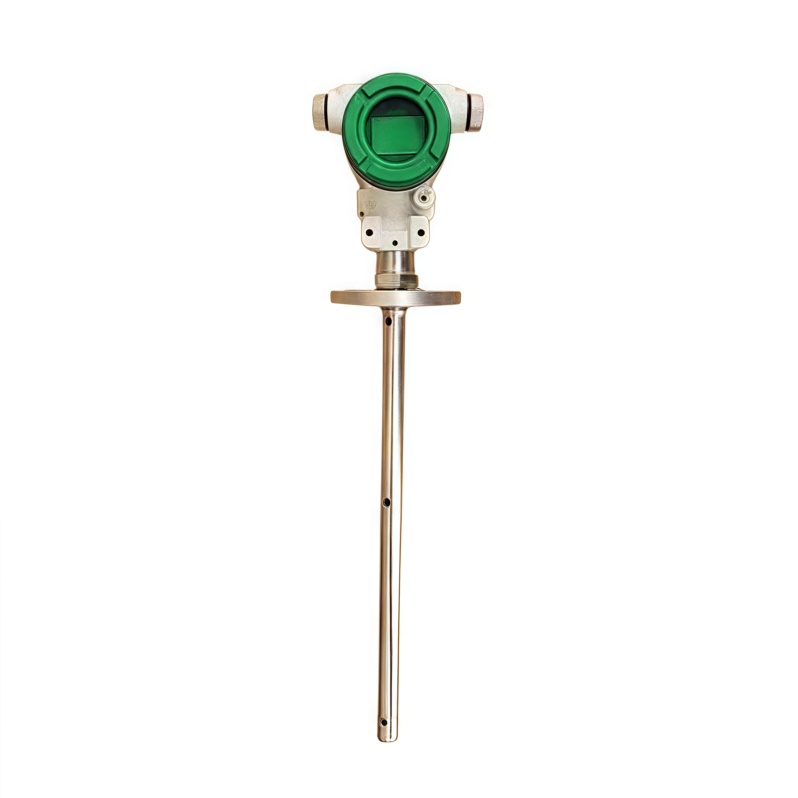
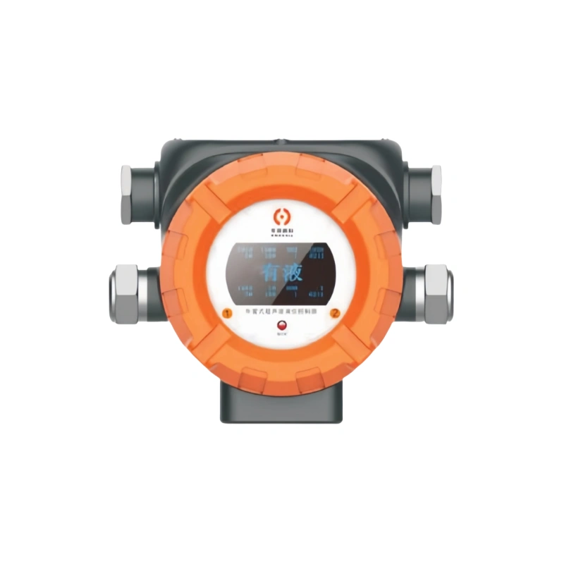
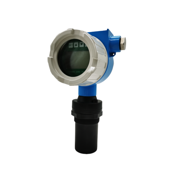
Ultrasonic Level Sensor
An ultrasonic level sensor consists of a complete ultrasonic sensor and control circuit. The ultrasonic wave emitted by the ultrasonic sensor reflects off the liquid surface, and the time required for return is calculated. A temperature sensor corrects for the temperature effect during ultrasonic transmission and converts the result into the distance between the liquid surface and the ultrasonic sensor. A 4-20mA analog signal is output via an LCD. Enable remote reading from the on-site instrument.
A level sensor is a key instrument for monitoring the liquid level or material height within a container during industrial processes. Its installation method directly affects measurement accuracy and stability.
I. General Installation Considerations
Signal Path Cleanliness: Ensure the beam path is free of interference such as foam, dust, or steam. Install a waveguide or purge device if necessary.
Calibration and Commissioning: After installation, perform calibration on both empty and full tanks, adjusting instrument parameters to match actual operating conditions.
Electrical Safety: Radar level sensors must be kept away from strong electromagnetic fields; ultrasonic level sensors should be kept away from high-frequency vibration environments.
II. Contact Level Sensor Installation Requirements
Contact level sensors include float level sensors, magnetostrictive level sensors, and hydrostatic level sensors. These level sensors come into direct contact with the fuel. Therefore, when selecting materials, consider compatibility with the measured medium. Also, select a suitable location when drilling holes in the tank.
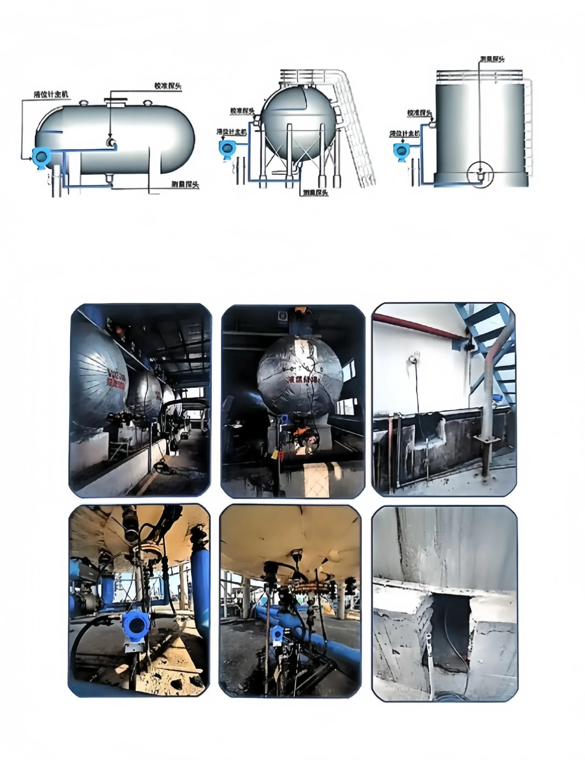
Mounting Location:
Preferably, installation is at the top of the connecting pipe leading from the top or side of the container. Ensure the float can move freely with the liquid level. The inner diameter of the flange connector must be larger than the float diameter. Prevent float sticking or friction that may cause measurement errors.
Connecting pipe design:
The connecting pipe must be kept vertical or tilted at an angle that does not exceed the range of the float’s motion. Ensure stable magnetic coupling between the float and the magnetostrictive rod.
III. Non-contact level sensor installation specifications
Non-contact level sensors include radar and ultrasonic level sensors. Non-contact level sensors do not come into direct contact with the fuel. Therefore, the following aspects should be considered when installing a non-contact level sensor.
Installation orientation and position:
The sensor must be installed vertically downward. Ensure that the beam (ultrasonic or radar wave) is projected directly onto the liquid or material surface. The distance between the beam center and the container wall must be greater than the beam radius at the lowest liquid level (calculated by the beam angle and the measuring range).
Environmental avoidance requirements:
Avoid equipment such as the feed inlet spray area, agitators, and baffles that may block the beam or cause signal interference. In high-temperature, high-pressure, or corrosive environments, appropriate protective materials or an insulating sleeve must be installed.
IV. Common Problems and Optimization Suggestions
Influence of Media Characteristics:
For viscous liquids or materials prone to crystallization, it is recommended to regularly clean the probe. Or choose a non-contact radar level sensor.
Temperature Compensation:
Under high-temperature conditions, ultrasonic level sensors require a built-in temperature sensor. Correct for sound velocity deviation.
Anti-Condensation Design:
In humid environments, radar level sensor antennas can be equipped with an anti-condensation cover. Prevent water droplets from adhering to the antenna and affecting the signal.
Fuel level sensors are a common device for measuring liquid levels. They can use different output signals to provide additional functionality and information.
Current Output Signal:
Accurate level measurement is provided through a current output signal. Current output signals are typically used for long-distance transmission. It has high immunity to interference. This makes fuel level gauge sensors widely used in industrial environments, particularly where automated control or data acquisition is required. The current output signal allows real-time monitoring of liquid level changes.
Voltage Output Signal:
Voltage output signals typically range from 0-10V or 0-5V and can be used to interface with other devices or systems. This output signal can be used in control and monitoring systems. such as liquid level alarm systems, liquid level displays, or data loggers.
The advantage of voltage output signals lies in their simplicity and universality. Make fuel level sensors compatible with a wide range of devices and systems.
Digital Output Signal:
Many fuel level sensors now offer digital output signals. Such as those using Modbus, Profibus, or Foundation Fieldbus communication protocols. This digital output signal can communicate directly with computers or other digital devices. And transmit liquid level data.
The digital output signal offers high accuracy and reliability. Enable more complex data processing and analysis. Furthermore, digital signals can be remotely monitored and controlled via the network. Enable remote management and fault diagnosis.
Pulse Output Signal:
Some fuel level sensors also provide pulse output signals. Pulse output signals are commonly used in metering and flow control applications. By counting the number of pulses generated by changes in liquid level, the flow rate can be calculated. This is crucial for systems that require monitoring and controlling liquid flow.