As a classic level detection instrument in the field of industrial automation, the rotary paddle level switch continues to play an irreplaceable monitoring role in process industries such as grain storage, the storage and transport of chemical raw materials, and building materials production, thanks to its significant advantages of being cost-effective, easy to maintain and highly adaptable to a wide range of environments.
Principle of Operation
The rotary paddle level switch detects material level by utilising mechanical rotation and changes in material resistance. An internal motor continuously drives the paddle to rotate at low speed.
When the material level in the container is below the position of the paddle, the paddle encounters no resistance and continues to rotate normally, whilst the switch maintains its original signal state. When liquid climbs up and finally touches the paddle, the substance pushes back against the spinning blade, bringing it to a halt.
The internal drive picks up on this sudden standstill, flipping the microswitch and sending out the appropriate open or close signal to show the material has hit the preset level.
Once the liquid falls back down and clears the paddle, the drag vanishes; the motor kicks the blade into motion again, and the switch falls back to its original position. That wraps up one full cycle of level sensing and switching. The setup is straightforward and dependable, and sees frequent use for keeping tabs on solid media like granules, powders, and lump materials.
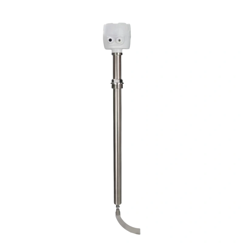
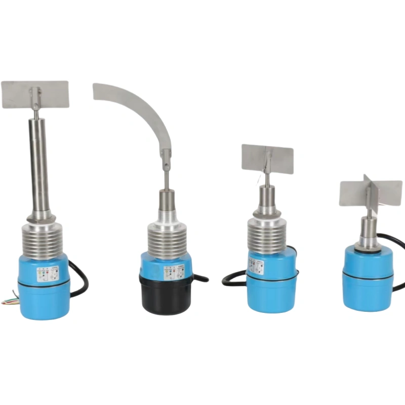
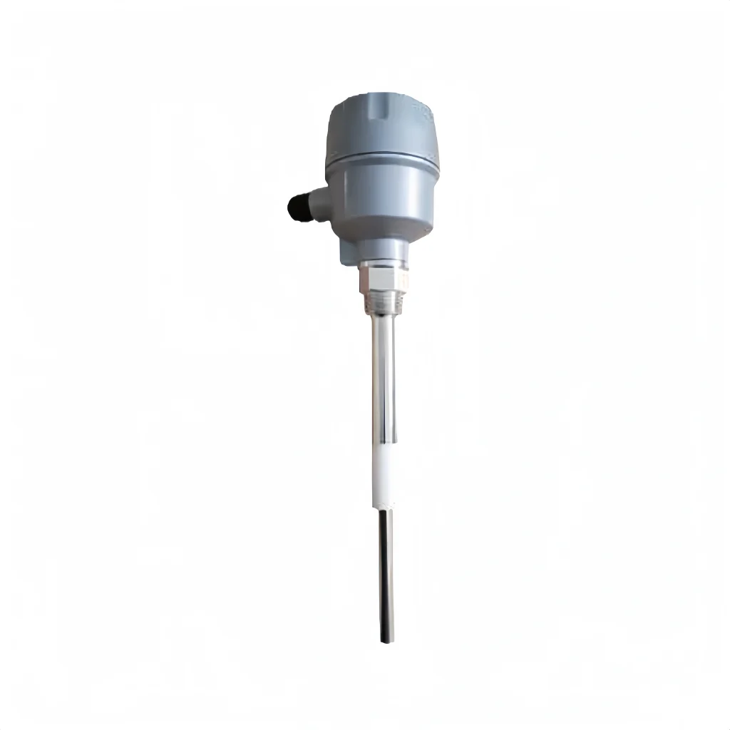
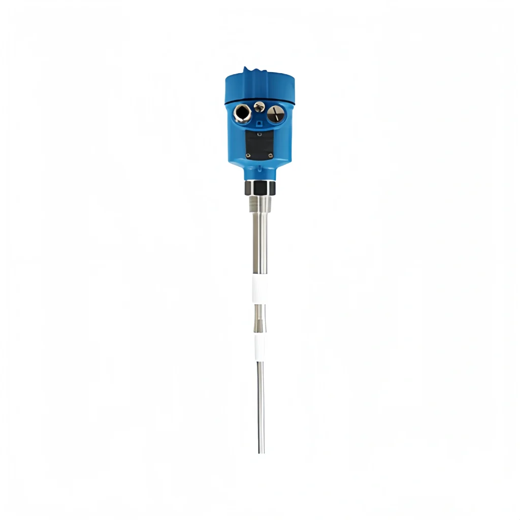
Basic Structure
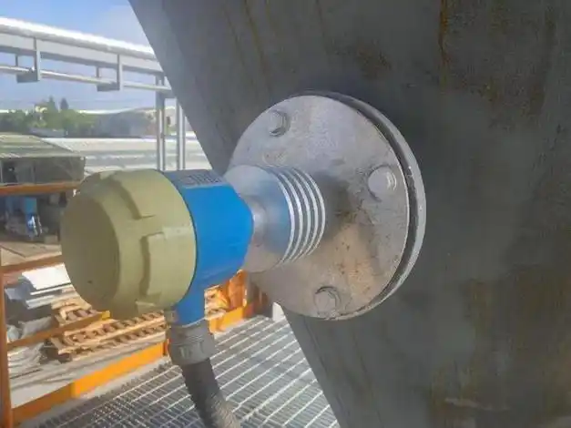
Drive Motor: Powers the whole setup, keeping the paddle spinning at its normal speed; it’s the heart of the equipment.
Transmission Assembly: Links the motor to the paddle, passing rotational force along, while working with resistance changes to carry out the mechanical shift.
Sensing Paddle: Touches the material directly. It changes how it behaves when the substance pushes back, which lets it figure out the level.
Micro Switch: Catches the signal from the transmission assembly, does the actual on/off flip, and puts out an electrical control signal.
Housing and Sealing Components: Keep dust and water out, making sure the guts of the unit keep running steady even when conditions get rough.
Terminal Blocks: Hook up to outside control circuits, sending switch signals on to whatever control systems or alarm gear comes next.
Key Features
Simple principle: A motor keeps the paddle turning; when material piles up to where the paddle sits, the drag forces it to quit spinning, which trips a switch signal. There aren’t any fancy electronics involved, so not much goes wrong.
Suitable Materials: Mainly built for checking levels of powdered, granular and chunky solid stuff like grain, cement, plastic pellets and ore; liquids are out of the question.
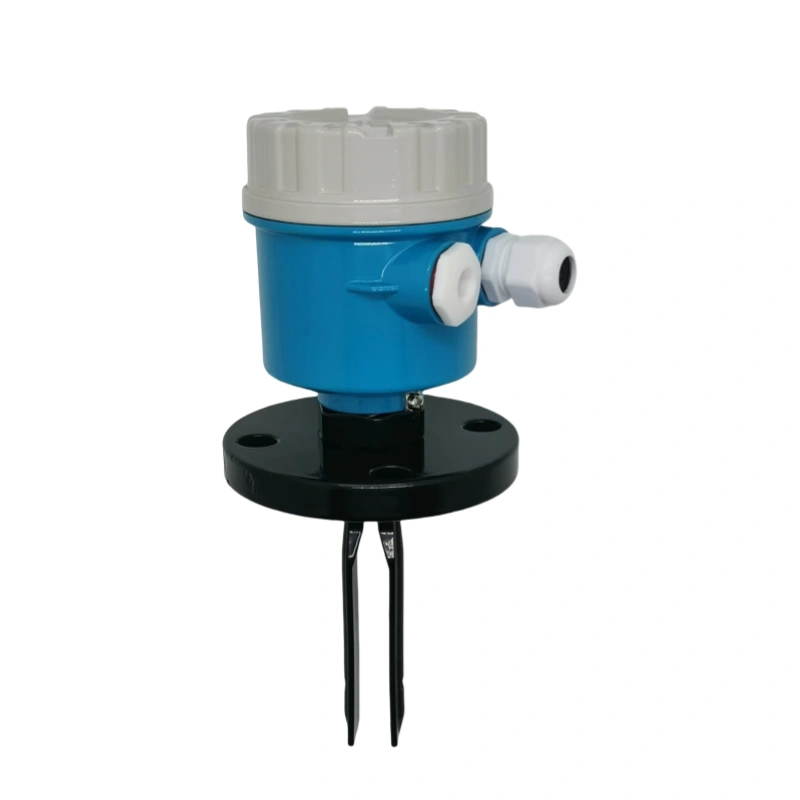
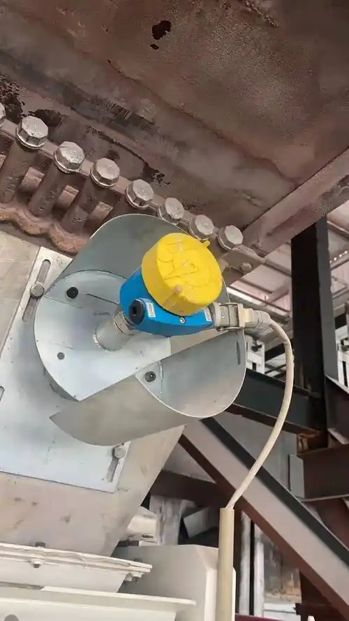
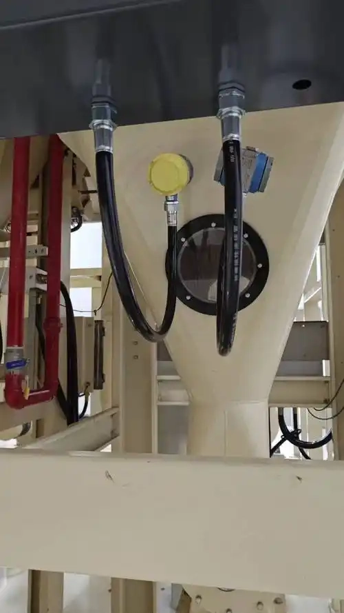
Flexible Installation: You can mount it straight down from the top, sideways through the wall, or at whatever angle works, so it fits different tank shapes and job site setups.
Robust construction: Usually made from stainless steel or carbon steel, it’s sealed up tight and can take dust, dampness and temperature swings without complaint, so it holds up fine in rough plant conditions.
Clear signals: Puts out a straightforward digital signal (relay output, for instance) that plugs right into a control system for high or low level alarms and hands-off automation.
Easy maintenance: The thing is built simply, so upkeep mostly means scraping built-up material off the paddle and giving the mechanical drive parts a once-over; you won’t be spending time on constant recalibration.
Cost-effective: Compared to electronic level switches such as radar or ultrasonic types, rotary paddle switches are lower in cost and offer excellent value for money, making them suitable for applications with limited budgets.
Overload protection: Some models incorporate a spring clutch or overload protection device; should the paddle encounter excessive resistance or become jammed, the motor is automatically protected to prevent burnout.
Practical Applications
Monitoring of bulk solid silos:
You’ll find these all over storage silos holding powdered or granular stuff like feed, grain, cement, plastic pellets and fertiliser. They fire off high-level or low-level alarms to stop things from spilling over when the silo’s packed or from running dry when it’s nearly empty.
Grain Processing and Storage Industry:
In places like rice mills, flour mills and grain silos, these sensors keep an eye on how high the grain has piled up inside the silo, at the bottom of elevators or inside conveying pipes. That lets the system handle feeding and discharge on its own without someone having to babysit it.
Chemical and Plastics Industry:
They go into hoppers and reactors loaded with solid materials like PVC powder, resin pellets and chemical raw materials. The sensors are built to survive dusty shop floors and still give you a solid, trustworthy signal for full or empty conditions.
Construction and Cement Industry:
Used for tracking material levels in cement silos, fly ash silos and aggregate silos. The tough build can take a beating from heavy material slamming into it and keep working fine through all the dust.
Feed and Food Processing:
These go into feed mixing silos and raw material silos on food processing lines. The materials used generally meet hygiene standards, and the sensors handle automatic feeding and line shutdowns.
Environmental Protection and Energy Sector:
They monitor material levels in biomass pellet fuel silos, wood chip silos and sludge treatment equipment hoppers, backing up automated feeding systems and keeping things from jamming up.
Mining and Metallurgy Industry:
Used for checking silo levels of coarse or heavy stuff like ore powder, slag and coke. The mechanical layout is fairly basic, so maintenance isn’t a headache even when working conditions are rough.
Advantages and Disadvantages
Advantages
1. Simple structure with few mechanical components, resulting in a low overall failure rate, minimal daily maintenance requirements and a longer service life.
2. Suitable for a wide range of materials, compatible with various powdered, granular and lumpy solid materials, unaffected by material colour or mild corrosion.
3. Tough against interference; dust, mist and vibration on the shop floor don’t throw it off, so the detection signals stay steady and dependable.
4. Goes in and comes online without a fuss; no headache calibration steps needed, and you can stick it wherever works—silo tops, walls, whatever fits.
5. Quick on the draw; when material hits the set level, it trips the switch signal fast, so you get timely control and alarms when you need them.
6. Doesn’t chew through much power while running, and if the lights go out it hangs onto whatever switch state it had before. Works fine with most industrial power setups.
7. Rated for serious protection and sealed up tight, so it keeps plugging away long-term even when it’s filthy with dust or dripping with humidity.
Disadvantages
1. Only works for solid materials; liquids and pastes are off the table, which really narrows down where you can use it.
2. The paddle rubs right up against the material; run it long enough and it wears down, and hard stuff speeds that wear up quite a bit.
3. If the material clumps up, bridges over or jams in there, the paddle can easily get stuck, which either sets off a false alarm or kills the detection altogether.
4. Not cut out for high-speed or high-impact jobs; a good knock from outside can bend the paddle or throw the shaft out of line.
5. With really fine powder, the stuff tends to cake on and stick to the paddle, which messes with normal rotation and drags down detection accuracy.
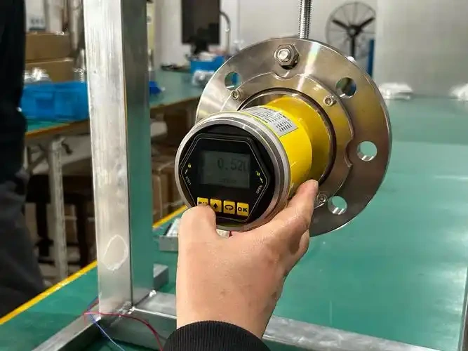
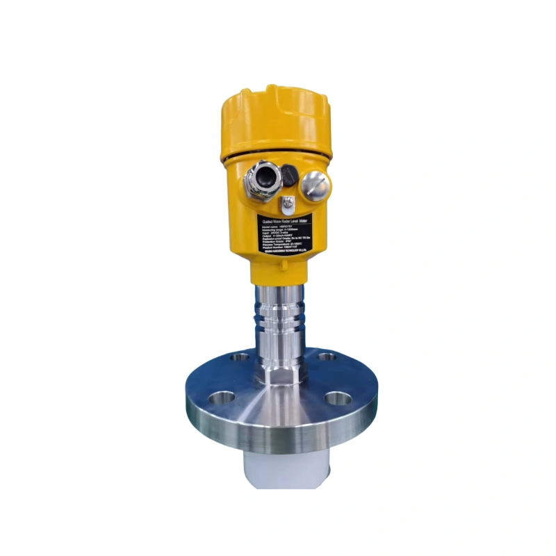
Installation Steps for Rotating Paddle Level Switches
1. Before you put it in, give the outside of the unit a once-over—the paddle, shaft and wiring bits—to make sure nothing’s bent, busted or seized up. Double-check that what you’ve got matches what’s needed on site.
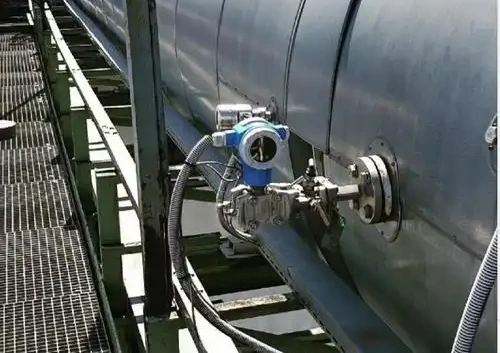
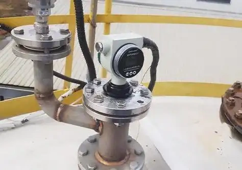
2. Pick where to mount it based on where you actually need to monitor in the silo. Go for flat spots on the wall or roof if you can, and steer clear of places where material comes crashing straight down or right near the feed inlet.
3. Cut your hole and lock the base down, keeping the mounting surface level or plumb. Cinch up the flange or threaded connections good and tight, and make sure the base is sealed up properly.
4. Put the paddle together, checking it’s solid on the shaft and spins freely without hanging up. Set the paddle angle to wherever you’ve decided the detection point needs to be.
5. Run the cables by the book, keeping them away from hot spots, sharp edges and corners, and places where material might squash them. Wire everything up per the diagram and tighten down the terminal blocks.
6. Hook up power and spin it empty to see if the blades turn right and the signal comes through like it should. Once you’re happy with how it’s running, you’re good to go live.
Installation and Operating Instructions
1. Install the unit away from the feed inlet and discharge area to prevent high-speed material impact on the blades, which could cause component deformation, damage or malfunction.
2. Strictly control the installation spacing; when installing multiple units of the same type, maintain a reasonable distance between them to avoid blade interference or collision.
3. For materials prone to caking or stickiness, increase the installation depth appropriately whilst ensuring sufficient maintenance space is provided to facilitate the removal of trapped or accumulated material.
4. In outdoor or damp, dusty environments, ensure the protective housing is intact and that sealing gaskets are not missing to prevent dust and moisture from entering the interior.
5. The equipment body must not be subjected to external pulling or impact forces. Mounting brackets must be secure to prevent the equipment from becoming loose or shifting due to silo vibrations.
6. Wiring work must be carried out with the power disconnected. Cables must be properly protected and secured; do not drag cables carelessly to prevent circuit damage and resulting faults.
7. In high-temperature or highly corrosive operating conditions, verify that the equipment’s materials are compatible with the on-site medium; standard models must not be used directly.
8. Once installation is complete, do not manually bend or twist the paddle blades. During routine inspections, monitor the rotation status; if any jamming or abnormal noises are detected, shut down the equipment immediately for maintenance.
9. When installing in inclined silos or hoppers, adjust the orientation of the paddle blades in accordance with the direction of material flow to ensure accurate detection triggering.
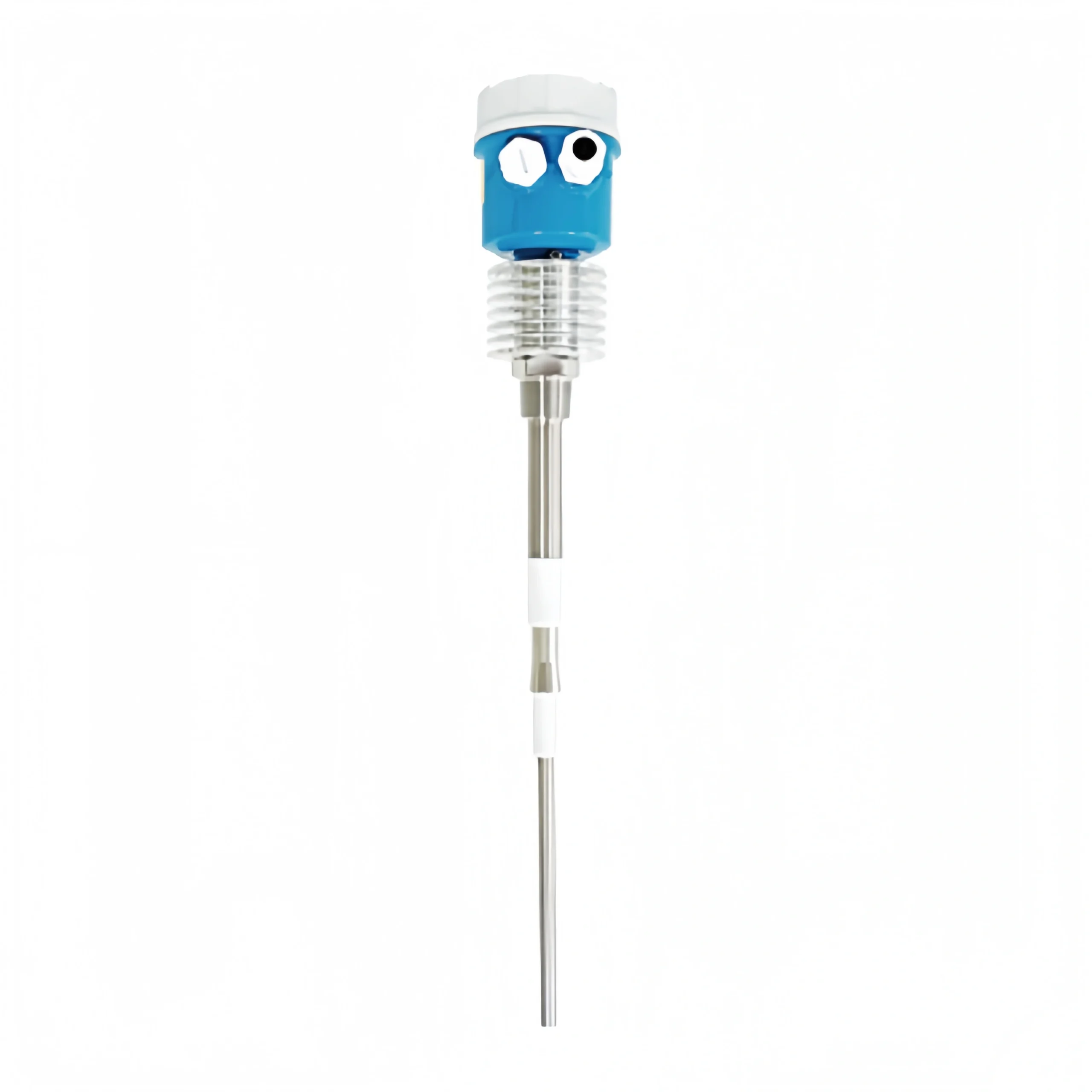
Comparison with Tuning Fork Level Switches
Working Principle
The rotary paddle type employs mechanical transmission for detection; a signal is triggered when material obstructs the rotating paddle blades. The tuning fork type determines the level by changes in vibration frequency and is classified as electronic induction detection.
Suitable Media
Rotary paddle switches are only suitable for powdered, granular and lumpy solid materials. Tuning fork switches offer greater versatility and can detect solids, liquids and viscous slurries simultaneously.
Operating Conditions
Rotary paddle switches are built tough and hold up well where material keeps slamming into them and dust is everywhere. Tuning fork switches don’t have any moving parts, so they can’t take a heavy hit; they’re better off in clean, normal environments and tight spots.
Faults and Service Life
Rotary paddle sensors have parts that move, which means they wear out and can get jammed up with material, so they tend to break down more often. Tuning fork sensors have nothing moving inside, so they run steady, give you fewer headaches and last longer.
Installation Features
Rotary paddle sensors can go in a few different ways, but you need to leave enough room for the paddle blades to spin around. Tuning fork sensors are small and go in easy, which works well for cramped spaces like pipes and small tanks.
Routine Maintenance
Rotary paddle-type sensors require regular cleaning of accumulated material and inspection of drive components, entailing a significant maintenance workload. Tuning fork sensors have a simple structure, requiring only basic cleaning and virtually no maintenance or calibration.
Response Speed
Rotary paddle-type sensors suffer from mechanical delay, resulting in generally slower response times. Tuning fork sensors are highly sensitive, offering faster signal switching.
Environmental Tolerance
Rotary paddle-type sensors offer superior resistance to high temperatures, moisture and dust, making them suitable for harsh outdoor and high-temperature environments. Standard fork-type sensors have relatively lower environmental tolerance; customised versions are required for special operating conditions.
Cost
Rotary paddle-type sensors are low-cost and economical. Fork-type sensors have a higher overall cost and are relatively more expensive.
Main Applications
Rotary paddle-type sensors are commonly used in large solid material silos for grain, cement, mining, and feed. Fork-type sensors are frequently used in chemical processing, water treatment, food and pharmaceuticals, as well as for monitoring pipelines and small tanks.
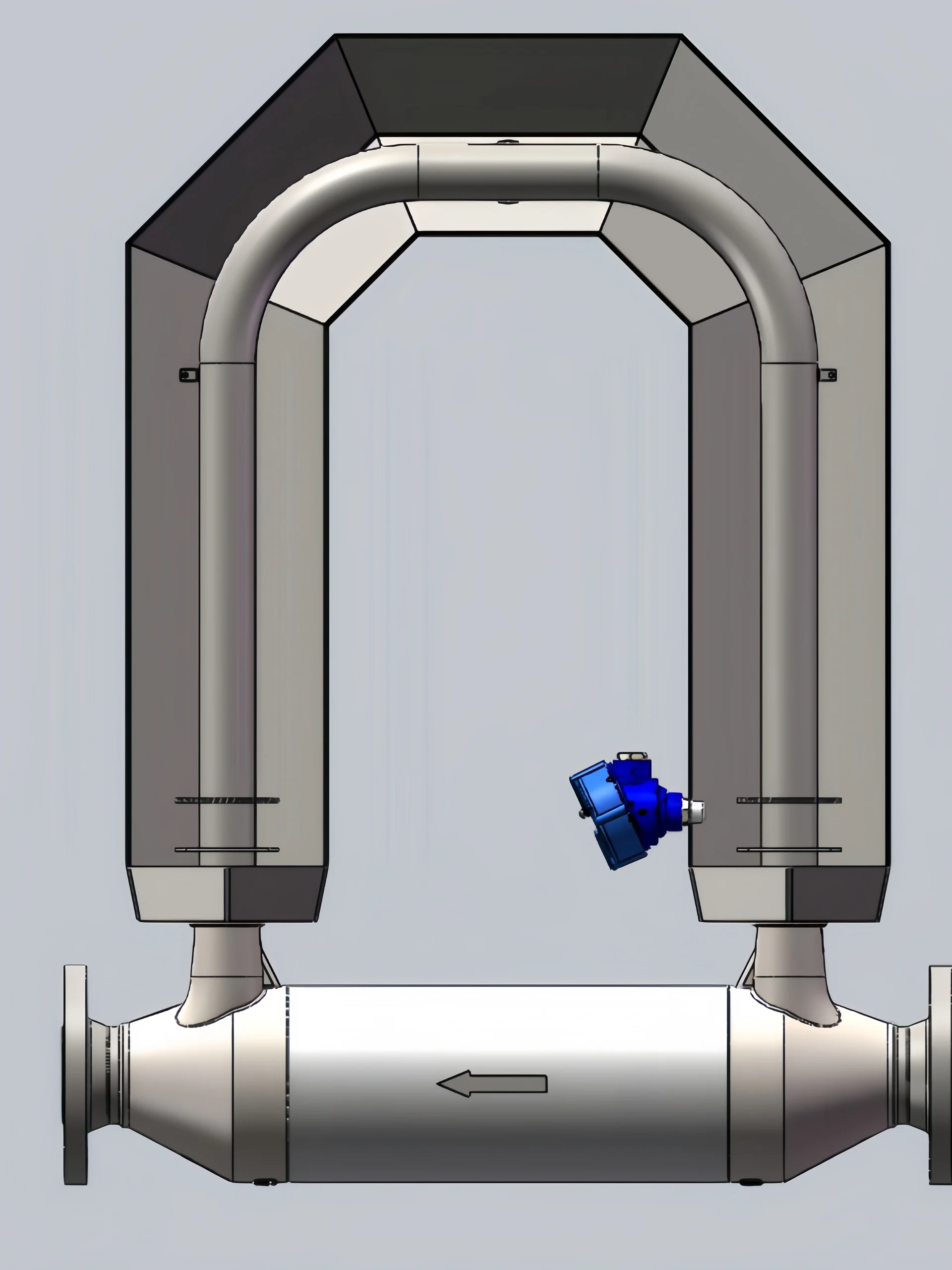
In addition to rotary paddle level switches, Sion-Inst offers a full range of level switch products, including fork-type, capacitive and radar models, allowing for flexible selection based on different media, operating conditions and detection requirements.
With mature technology and reliable product quality, we provide one-stop solutions for level monitoring scenarios across various industries, helping enterprises achieve stable automated operations.