Along with pressure transmitters, valve assemblies are crucial. They improve pressure measurement setups and equipment reliability. These devices can rapidly detect fluid pressure and regulate multi-path signals thanks to their high-quality mechanical and sensor components.
They are crucial to energy facilities, aircraft systems, and factory automation because their condition affects measurement accuracy and system reliability.
What Is a Pressure Transmitter Valve Manifold?
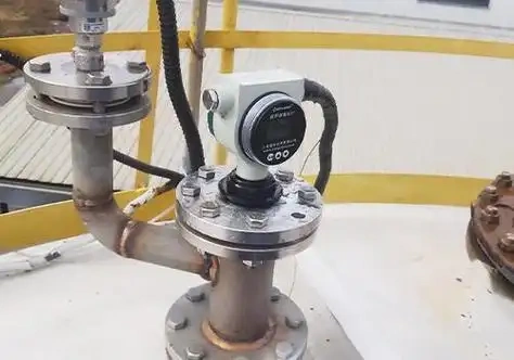
Pressure transmitter valve manifolds are designed for pressure transducers. It connects process pressure take-off locations to pressure transmitters, which is pretty much a must-have for industrial pressure monitoring.
This tiny manifold houses shut-off, balancing, and relief valves. The ones you see most often are two-valve, three-valve, and five-valve versions for standard pressure and differential pressure testing.
These valve sets are compact and easy to put in place. They let workers sample, balance, and release pressure from one locati0n. You will find them all over chemical plants, power stations, and petroleum industries to keep transmitter measurements in check and maintain safety.
The Importance of Valve Assemblies
1. Ensuring Safety During Equipment Maintenance
When calibrating or servicing pressure transmitters, valve manifolds do the heavy lifting of isolating impulse lines, equalizing internal pressure, and bleeding off whatever’s still in the pipe. This cleanly separates the instrument from the process side.
Technicians can swap out transmitters without dumping system pressure, which means no fluid escaping and no nasty pressure spikes. That translates to fewer hazards on the ground and better protection for the crew.
2. Improving Measurement Accuracy
Valve manifold units equalize pressure across both sides of a differential pressure transmitter, making zeroing straightforward and knocking out baseline drift. The seals hold up well over time, so you don’t get leaks or signal shift. Readings stay tight and consistent, which matters when you’ve got equipment running in the field for years.
3. Simplified Operational Workflow
The integrated design cuts down on field piping and eliminates a pile of separate fittings. Commissioning, venting, and calibration all happen through basic valve operations, so instrument maintenance takes less time and fewer headaches.
4. Transmitter Protection
Sudden pressure swings, brief pressure surges and accumulated debris will wear down delicate internal parts over time. This integrated valve unit cushions abrupt pressure impacts to safeguard precision diaphragms, while also filtering out contaminants in the pipeline.
It effectively cuts down corrosion and clogging issues, helping minimize equipment breakdowns and prolong overall service life.
5. Adaptability to Complex Operating Conditions
Regular repair and field testing can be done by technicians right where the equipment is, without having to shut down the line.
There are different styles of these valve systems, and they work well in tough situations with normal pressure, differential pressure, or media that is acidic. The process keeps going without stopping, and the measurements stay the same.
Types of Valve Assemblies for Pressure Transmitters
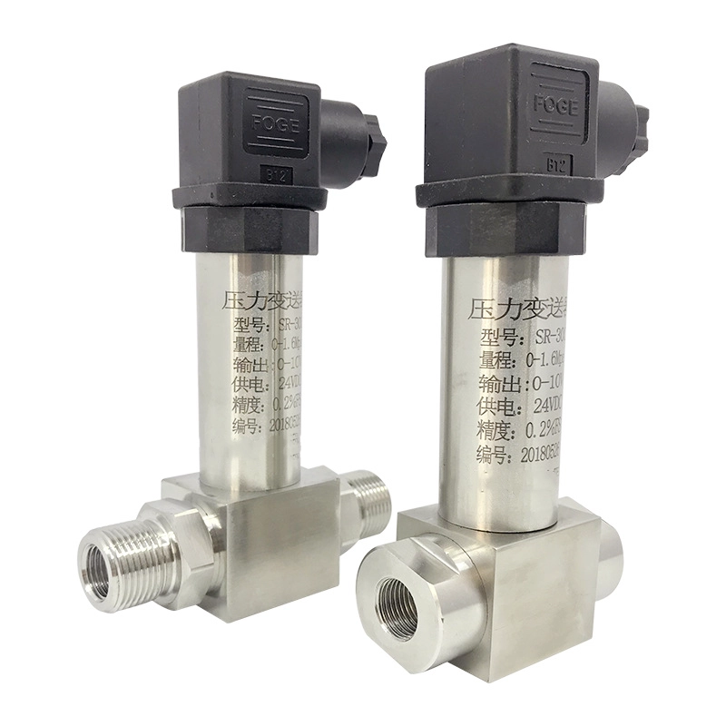
Dual-Valve Manifold
This manifold is one of the most basic valve setups out there, with a pretty simple overall structure. It pairs an isolation valve with a vent valve to form a two-port design.
Built mainly from carbon steel or stainless steel, it handles general pressure service and remains the most straightforward manifold option to pair with pressure transmitters.
Advantages:
1. Its compact, uncomplicated structure takes up little space and installs quickly, ideal for common regular mounting scenarios;
2. With fewer parts involved, it rarely malfunctions, runs steadily and requires almost no regular upkeep, while keeping overall expenses low;
3. It delivers great value for money, works well with a broad range of materials, performs reliably in standard low-pressure environments and boasts strong general applicability.
Application Scenarios:
It works well for basic single-pressure measurement systems that run under steady conditions. It meets regular needs for isolation, pressure relief and venting, and is widely adopted in general low-pressure industrial measurement work.
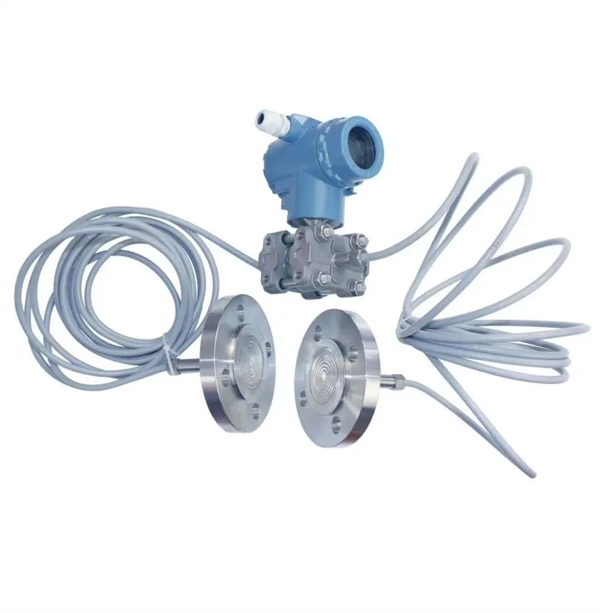
Three-Valve Manifold
This is a widely used manifold across industrial fields. It adopts a three-port layout built with two isolation valves and one balancing valve.
Available in carbon steel, stainless steel and different alloy grades, it fits most general pressure working environments and is mainly matched with differential pressure transmitters.
Advantages:
1. The integrated pressure balance design evens out pressure between the high and low sides. This stops sudden pressure spikes from harming the transmitter’s sensor unit.
2. It keeps pressure readings precise and consistent, while also boosting safety during daily operation and on-site maintenance.
3. Practical and budget-friendly, it fully meets the demands of most conventional industrial differential pressure measurement tasks.
Applications:
It is extensively applied in differential pressure measurement systems that need pressure balance between transmitters and production lines. This manifold serves as a standard fitting for regular pressure monitoring in chemical, power, metallurgy and other industrial sectors.
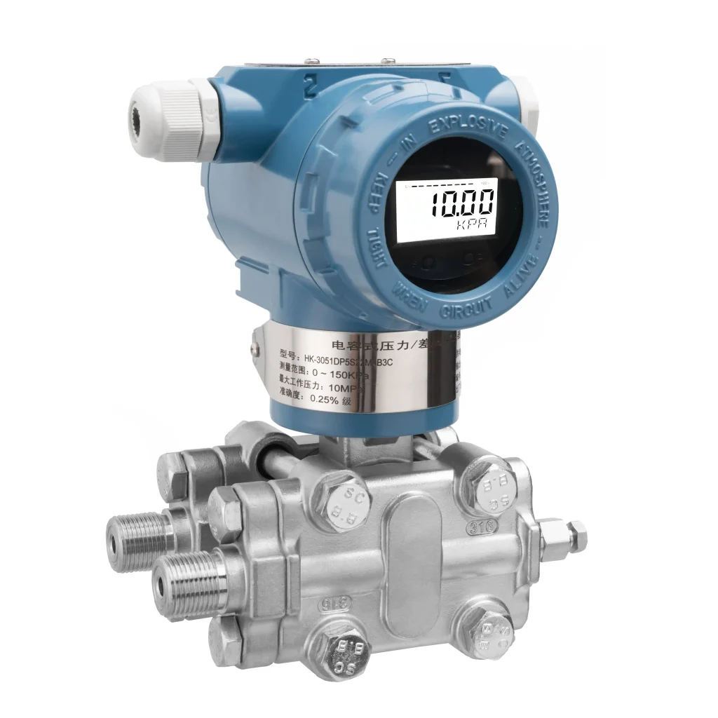
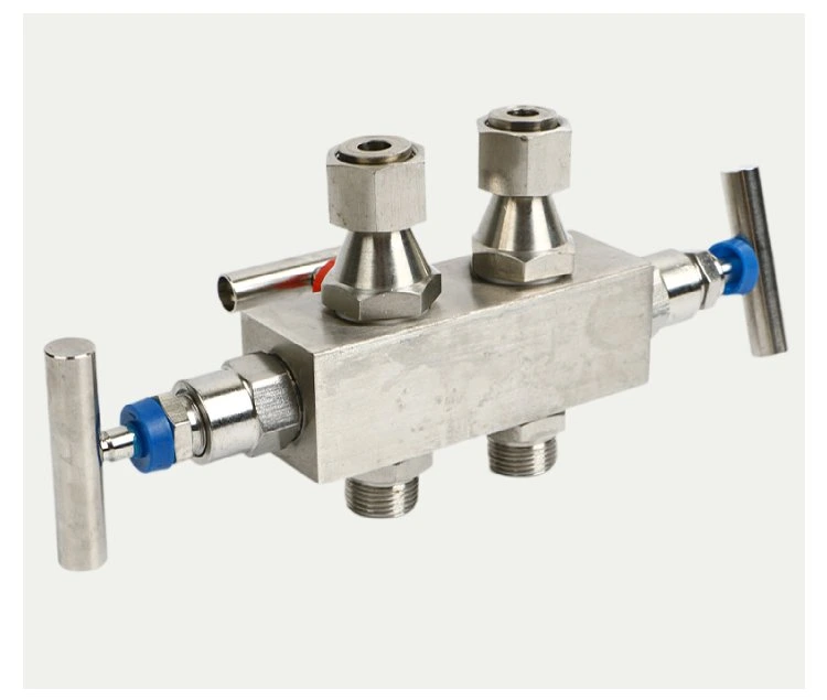
Five-Port Manifold
A multifunctional, high-end composite valve assembly featuring a five-port configuration. It integrates 2 isolation valves, 1 balancing valve, 1 vent valve, and 1 drain valve.
Primarily constructed from high-quality materials such as stainless steel and special alloys, it offers high pressure resistance and is suitable for high-pressure and complex, variable operating conditions.
Advantages:
1. This unit has features for isolating, adjusting pressure, venting, and emptying all in one, so you don’t need any extra parts.
2. It is made of strong pressure-rated materials that keep it stable even in difficult working conditions and high pressures. It also has good resistance to interference and rust.
3. It maintains stable and dependable measurement performance while providing reliable protection. The product complies with rigorous accuracy and safety criteria and features an extended service life.
Application Scenarios:
This product is tailor-made for industrial systems operating under high pressure and complex working conditions, as well as pipelines where liquid and impurities tend to build up. It is extensively applied to precision pressure measurement tasks that demand high measurement precision, equipment safety and standardized operation.
Functions of the Pressure Transmitter Valve Assembly
1. It regulates the connection between pressure transmitters and process measuring pipelines. Staff can cut off the medium flow independently, so on-site equipment can be maintained, detached or replaced without disrupting normal production.
2. It equalizes pressure on the high and low pressure sides of the transmitter. When the balance valve is opened, pressure in the two chambers levels out. This facilitates zero calibration work and guarantees consistent, accurate measurement results.
3. It handles pressure release and medium drainage. The drain valve flushes out leftover fluid, trapped air and grime from impulse lines. This prevents pipe clogging and rules out reading errors brought on by pipeline issues.
4. Provides effective isolation for pressure tapping points. During routine maintenance, closing the two side stop valves cuts off the process medium supply. This protects internal precision components of the transmitter from sudden pressure impact and medium corrosion damage.
5. Standardizes the startup and shutdown procedures of field instruments. Standardized valve opening and closing operations enable smooth switching of the transmitter’s working status, and prevent equipment failure or damage resulting from abnormal one-way pressure load.
Applications of Pressure Transmitter Valve Assemblies
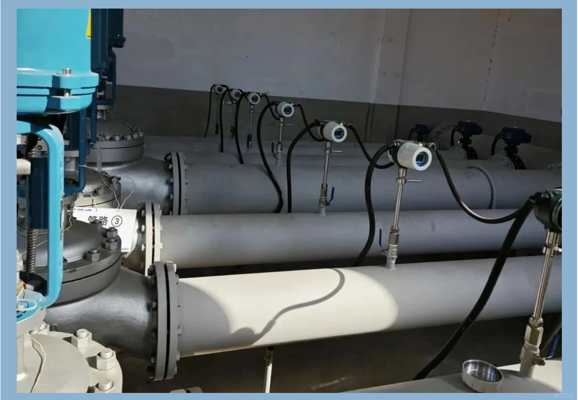
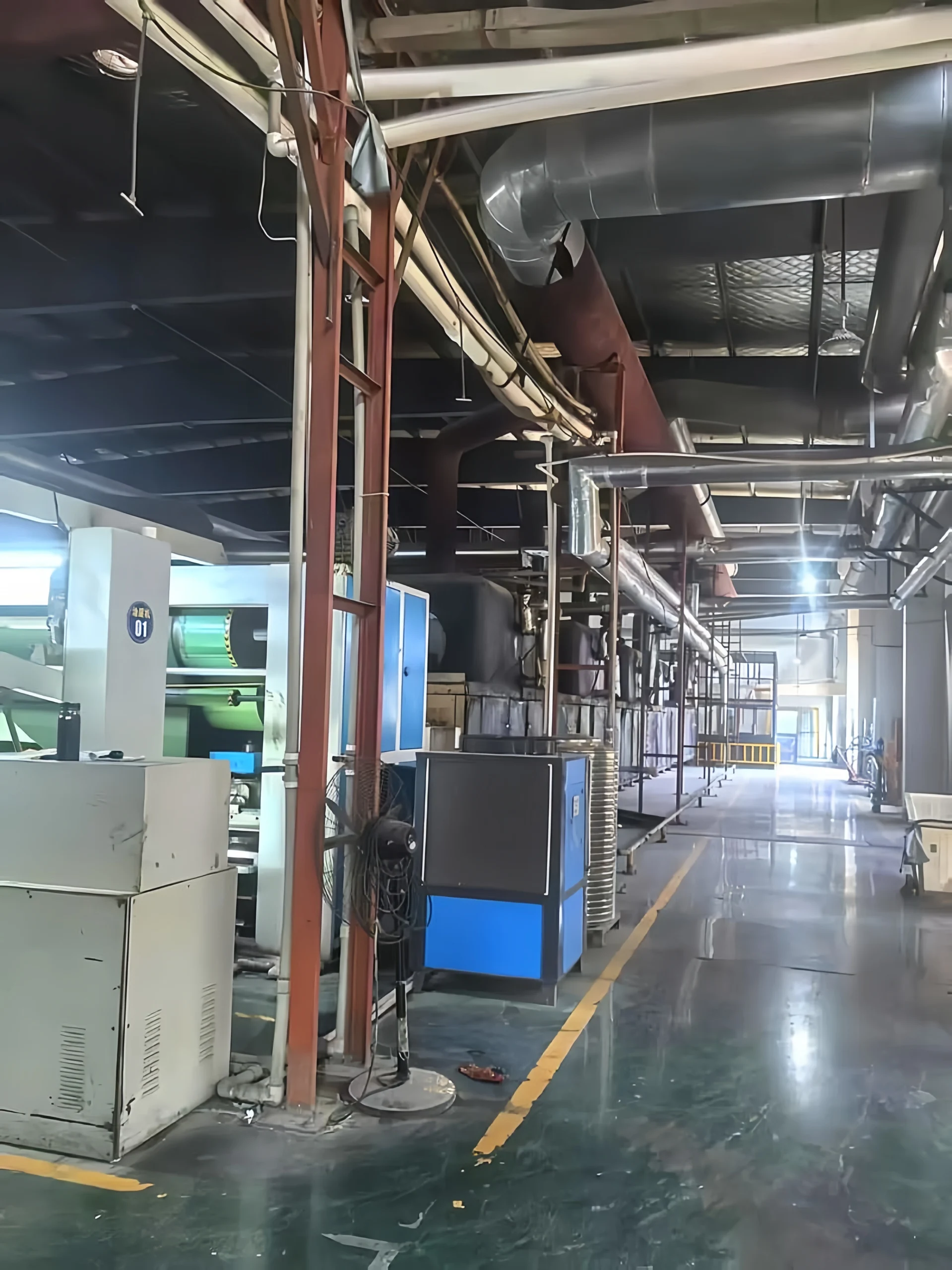
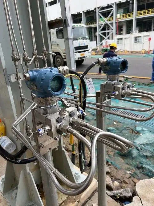
1. Commonly deployed in petroleum, chemical, power generation, metallurgy and other industrial production scenarios, this matching system works with pressure and differential pressure transmitters to track real-time pressure and differential pressure values for pipelines, storage tanks, reactors and other process equipment under diverse operating conditions.
2. This method works great for checking the amount of liquids on-site. With the help of impulse pressure lines and switchable valve manifolds, it can constantly check the level of liquid in sealed containers and storage tanks, giving workers accurate readings.
3. Parts of differential pressure flow systems, like orifice plates and Venturi tubes, work with these valve units to measure flow in factories. They pick up difference pressure readings very accurately on the spot, which is what you need to get useful flow data.
4. The useful form of the valve also makes instrument maintenance and inspections much easier to do on-site. It’s easy for field workers to take transmitters out of service to calibrate them or fix problems. This cuts down on production downtime and keeps operational costs to a minimum.
5. This product is made to work in harsh conditions, such as places with high temperatures, high pressure, and chemicals that eat away at metal. The way it’s built successfully removes process media from instruments. This keeps harsh fluids and sudden pressure spikes from damaging transmitters and extends the life of instruments.
6. It is extensively applied in industrial automatic control systems. It can transmit stable and reliable field pressure signals to DCS, PLC and other mainstream control platforms, providing basic data support for automatic process adjustment and safety interlock protection of the whole production system.
Selection Guide
I. Matching Media and Operating Pressure Ratings
Pressure Parameter Matching: Model selection should strictly follow the maximum operating pressure and design pressure of on-site process pipelines. Choose a valve assembly with a pressure grade that matches or exceeds matching transmitters and piping systems.
Standard valve assemblies can be used for general working circumstances, but high-pressure operating scenarios require specialist valve models to minimise medium leakage and valve body deformation.
Matching media: Carbon steel valve manifolds work well with water and compressed air. Use 304 or 316 stainless steel for acids, alkalis, and other corrosives. Choose valve bodies with broader flow pathways for viscous or crystallising fluids. The design prevents internal obstructions and false readings from clogged pipes.
II. Determining Valve Assembly Type and Functional Structure
Selection Based on Measurement Scenarios: For routine pressure monitoring, basic two-valve sets will do the job. Differential pressure transmitters typically call for three-valve assemblies, which handle pressure balancing, relief, and instrument protection without much fuss.
If you’re dealing with high-precision work that needs regular calibration and frequent tweaks, five-valve integrated assemblies are worth the investment—they pack all the functions you need into one unit.
Selection by Installation Configuration: In open pipeline areas, go with split-type valve assemblies; they’re easier to put in and take out when you need access. For cramped spaces like crowded cabinets or tight pipeline clusters, integrated valve assemblies make more sense since they don’t eat up much room.
III. Selection Based on Temperature and Environmental Conditions
Adapt to medium temperature: Conventional sealed valve assemblies fit well with media operating at normal ambient temperatures. For working conditions involving high-temperature steam, heat transfer oil and other high-heat media, valves equipped with heat-resistant sealing parts are required. This practice prevents seal deterioration and medium leakage triggered by sustained high temperatures.
Adapting to Site Conditions: For outdoor installation sites with high humidity, heavy dust and harsh open-air conditions, operators should adopt rust-proof valve assemblies with high-level protection performance. For flammable, explosive and other hazardous industrial areas, leak-tight explosion-proof valve configurations that produce no external sparks must be selected to comply with on-site safety regulations.
IV. Verifying Connection Specifications and Installation Compatibility
Match Interface Parameters: Before installing, field workers must check all thread, ferrule, and flange specs to make sure that valve assemblies, pressure sensors, and impulse tubes can all work together.
When you do the right interface matching during the planning stage, you can get rid of assembly mismatches, which stops fluid leaking problems after the installation is done.
Make sure operational ease: The general layout of the system must leave enough room for daily upkeep tasks like switching valves, draining medium, and calibrating instruments.
It is best to choose valve kits that have luxury sealing structures and valve cores that have been finely processed. This design restrains zero point drift and ensures long-term stability of measurement data for the entire system.
FAQ
What is the difference between a manifold valve and a valve manifold?
1. Structural Design
Integral manifold valves use a one-piece body where all internal flow passages are cast directly into a single component. The result is a compact layout with piping built right into the body itself.
Valve manifolds, on the other hand, are put together from individual valves, fittings, and short connecting tubes—so you can pull apart and swap out specific parts as needed.
2. Connection Layout
Manifold valves ship with fixed port arrangements: the channel directions and port sizes are set at the factory, leaving no room for field adjustments.
Valve manifold sets give you far more leeway—you can pick the connection style and route the piping to match whatever the actual site conditions demand.
3. Sealing Performance and Leakage Points
The one-piece construction of integral manifold valves minimizes external connection points, greatly lowering leakage risks and delivering reliable pressure resistance and sealing capability.
As assembled combinations of multiple accessories, conventional valve manifolds have more threaded and joint connections, making them more prone to potential leakage issues.
4. Application Scenarios
Integral manifold valves are mainly matched with field instruments installed closely to process equipment, and are widely applied in compact installation scenarios for differential pressure transmitters and pressure transmitters.
Assembled valve manifolds are more ideal for complex piping layouts, long-distance pressure signal sampling and on-site pipeline renovation and upgrading projects.
5. Maintenance and Cost
Manifold integral valves are generally replaced as a complete unit. Partial component damage cannot be repaired separately, leading to higher individual product costs.
Valve manifolds support independent replacement of faulty single valves and accessories, which simplifies daily maintenance work and effectively reduces overall operating and maintenance expenses.
Can a 2-valve manifold be used with a DP transmitter?
No
Differential pressure transmitters need two distinct pressure connections—one for the high side and one for the low side—to get a proper differential reading. A two-valve manifold only has a single process inlet, so it can’t tap into both pressure sources simultaneously. That rules it out for differential pressure work.
How do I check the zero of a DP transmitter using a 3-valve manifold?
A typical three-valve manifold consists of a high-pressure isolation valve, a low-pressure isolation valve and a balance valve. The calibration process adheres to the standard operating rule: open the balance valve first before shutting off the process isolation valves:
- Gradually open the balance valve to interconnect the transmitter’s high-pressure and low-pressure cavities, until the pressure on both sides reaches a fully consistent state.
- Shut down the high-pressure valve followed by the low-pressure valve step by step to isolate the entire process medium pressure source.
- Observe the transmitter’s display value; if there is no deviation, the zero point is normal. if there is a deviation, adjust the zero-point screw on-site until the reading is zero.
- After zero-point calibration is complete, open the high- and low-pressure valves first, then close the balancing valve to resume normal measurement conditions.
Can valve manifolds be expanded after installation?
1. Integrated 3-valve/5-valve manifolds: The factory-built structure is locked in place, so expanding it on-site is not happening—you cannot add more channels or valves after the fact.
2. Modular valve assemblies: You can tack on extra valves, bypasses, drain ports, vent ports, or whatever else the job calls for. These setups also leave room for future expansion when pipelines need more capacity or additional functions down the road.
All industrial facilities need precise pressure monitoring to operate safely. Fluid processing, material storage, pipeline media transit, automated process control, and daily maintenance are all affected by it. Getting the right valve manifold and installing it properly goes a long way toward keeping production safe, measurements accurate, and energy costs down.
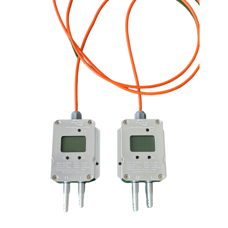
Sino-Inst offers two-, three-, and five-valve industrial valve manifolds for various on-site needs. These flexible setups can handle ordinary operating circumstances, differential pressure testing, high-pressure corrosive environments, and high-precision measurement and control. They also work directly with pressure transmitters to give industrial locations a complete measuring solution.