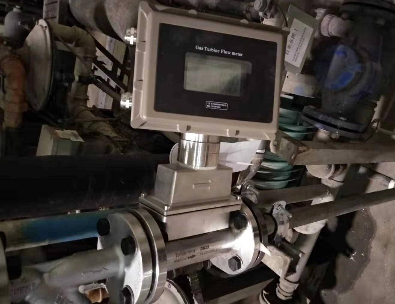
Turbine flow meters are used a lot in lots of different industries like petroleum, chemical engineering, metallurgy and water supply and drainage to measure flow. It’s super accurate, responds quickly, and has a wide turndown ratio. However, their metrological performance is highly sensitive to external factors such as installation environment, pipeline conditions, and fluid state. Correct installation is not only fundamental to ensuring the instrument’s normal operation but also a core prerequisite for realising its technical advantages, mitigating measurement risks, and safeguarding production compliance.
Working Principle
The turbine flowmeter is a velocity-type flow measurement instrument, operating on the principle illustrated below. A turbine is positioned at the centre of the pipeline, supported at both ends by bearings. When fluid flows through the pipeline, it impinges upon the turbine blades, generating a driving torque that causes the turbine to rotate despite overcoming frictional torque and fluid resistance torque.
Within a defined flow range and for a given fluid viscosity, the rotational angular velocity of the turbine is directly proportional to the fluid velocity. Consequently, the fluid velocity can be determined from the turbine’s angular velocity, thereby enabling calculation of the fluid flow rate through the pipeline.
Comparison of Installation Methods
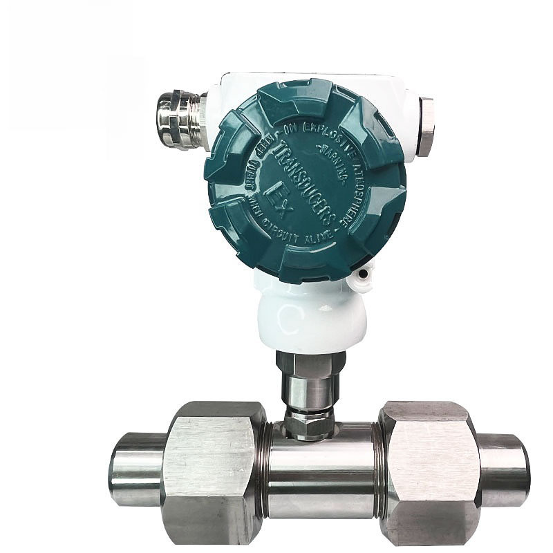
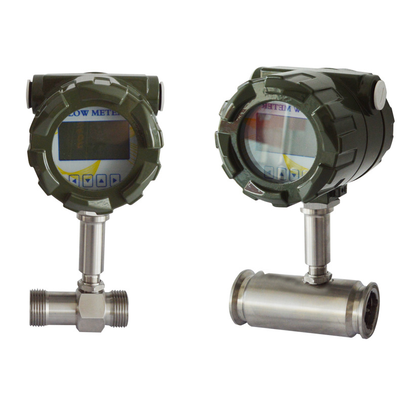
Threaded Installation
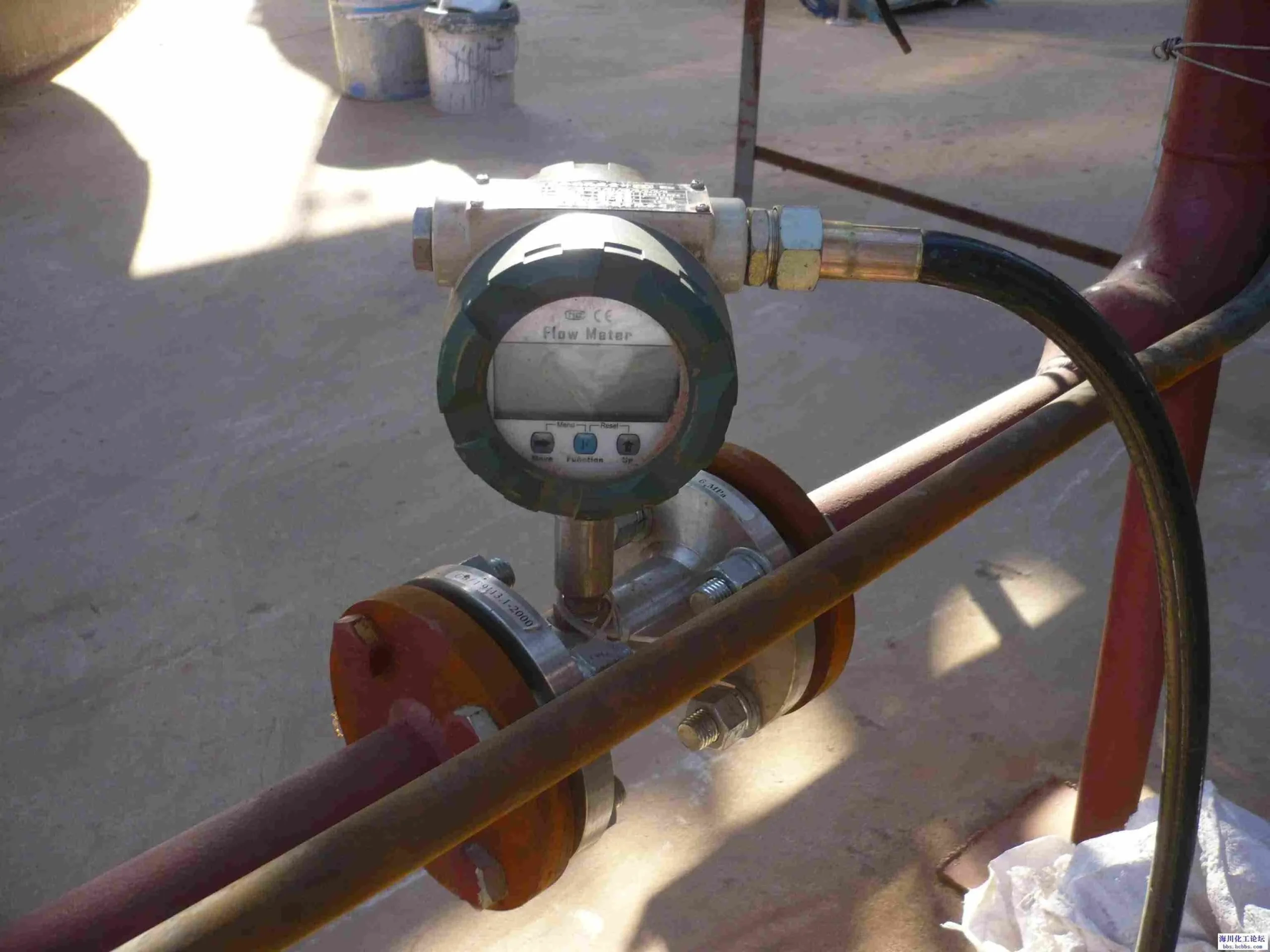
Thanks to its threaded design, the flow meter can be connected to the pipeline via threads at both ends, eliminating the need for large fittings. It is ideal for small-diameter pipes ranging from DN2 to DN40 and has a pressure resistance of up to 4.0 MPa. This makes it ideal for domestic gas applications and small-scale industrial low-pressure scenarios with moderate flow rates.
Advantages: Easy installation and removal, compact footprint, low cost, and excellent sealing performance. Suitable for confined spaces and applications requiring infrequent maintenance.
Disadvantages: It can’t handle high pressure or big diameters, so it’s not suitable for those applications. It needs to be installed really precisely, and you have to take it all apart to do any maintenance, which messes up the fluid flow.
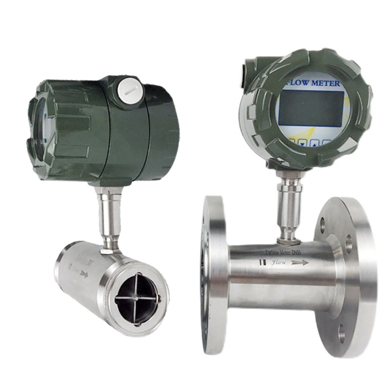
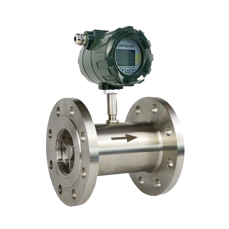
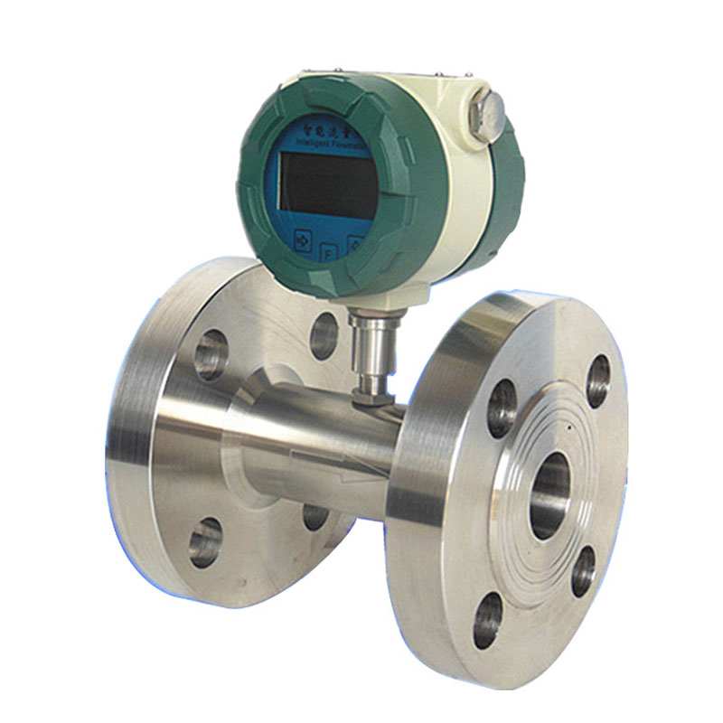
Flange Installation Method
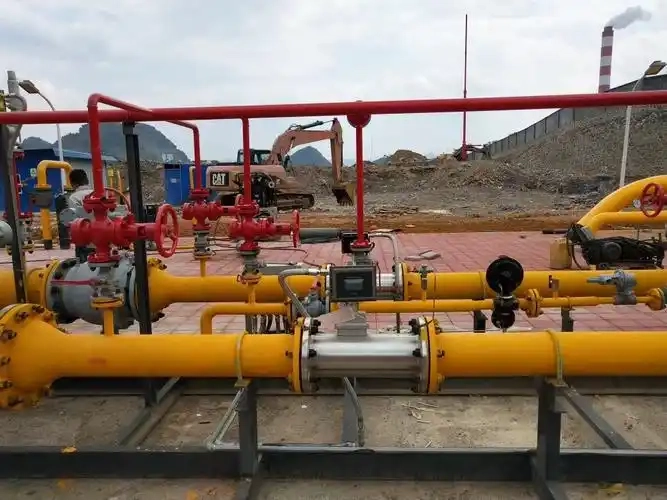
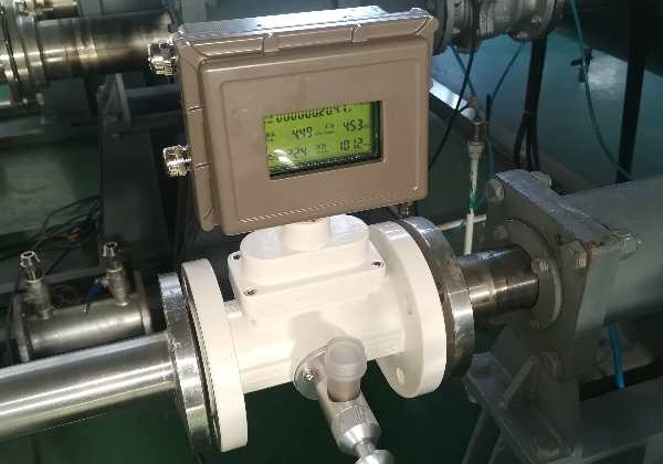
The flange installation secures the flowmeter to the pipeline flanges via bolts, which is the standard industrial approach. It works with all diameters from DN2 to DN300 and above, and it can handle high pressure and temperature, so it’s used a lot in gas and liquid metering in petroleum, chemical, and related industries.
Advantages: Secure connection, high pressure resistance, excellent sealing, high accuracy, individual component removal for maintenance, adaptable to complex conditions.
Disadvantages: Requires matching flange bolts, higher cost than threaded installation, larger footprint, stringent construction standard requirements.
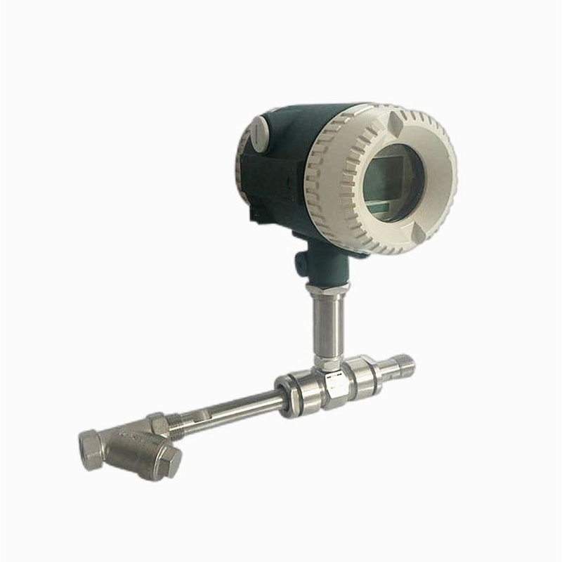
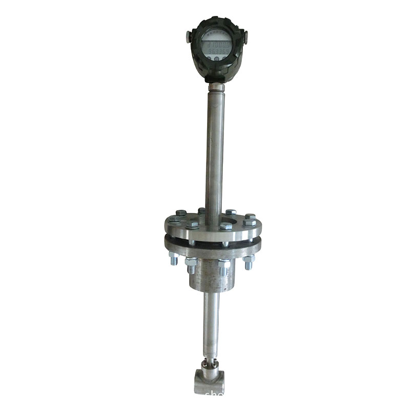
Insertion Installation Method
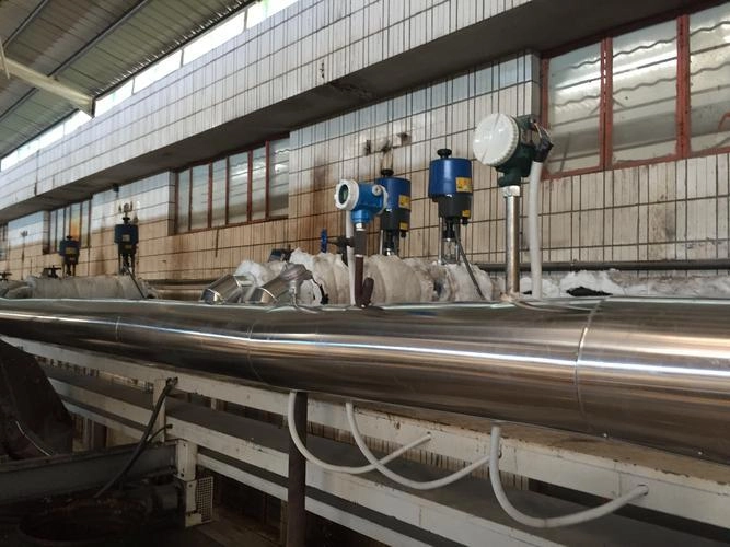
The insertion installation involves putting the measuring probe into the pipeline without stopping the flow. You just need to drill a hole to install the mounting bracket. This method is great for large diameters of DN100 and above, non-full-bore conditions, or situations where shutting down for modification isn’t practical.
Advantages: Simple installation, no disruption to production, suitable for large diameters, lower cost than flange installations of the same diameter, and the probe can be removed for maintenance.
Disadvantages: Slightly reduced measurement accuracy, significantly affected by fluid velocity distribution, unsuitable for high-pressure/high-viscosity media, demanding sealing requirements.
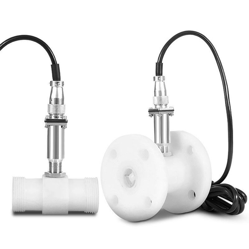
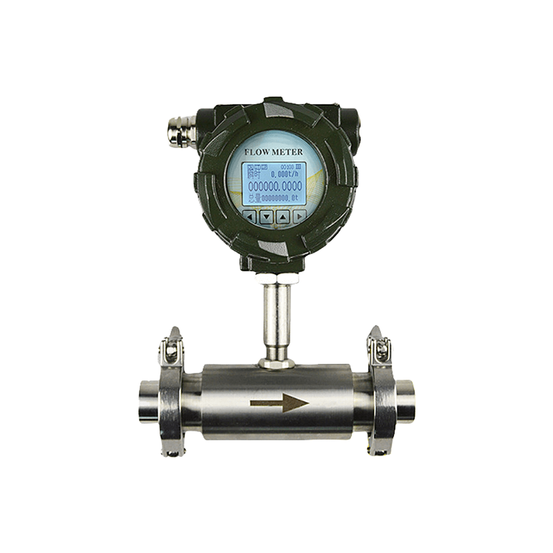
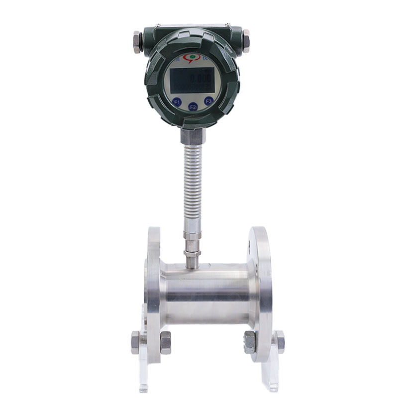
Clamp (Bonded) Installation Method
The clamp (bonded) installation uses special clamps to hold things securely in place, with sealing rings to keep everything contained, and you don’t need to do any welding or threading. It’s perfect for small to medium diameters (DN2-DN50), low-pressure conditions at room temperature, and is often used in sanitary applications like food and pharmaceuticals.
Advantages: Installation and removal are a breeze; there’s no need for any special tools; it won’t cause any damage to your pipes; and it’s a piece of cake to maintain.
Disadvantages: It can’t handle high pressure, high temperature or big pipelines; it needs precise pipe alignment; it’s prone to leakage if tightened improperly; and it’s not suitable for high viscosity or impurity-laden media.
Installation Procedure
Threaded Turbine Flow Meter
- Pre-installation Preparation: Prepare matching threaded fittings, sealing tape/gaskets, wrench, and 5-micron mesh filter. Verify the flow meter’s directional arrow aligns with the actual medium flow direction.
- Pipeline Preparation: Make sure the pipeline threaded interface is clean and free of any rough bits or pieces. This will help to ensure that the threads are in good condition and undamaged. Use some sealing tape or a sealing ring on the threaded part of the flow meter to make it all nice and tight.
- Main Unit Installation: Just make sure you mount the flow meter horizontally on the pipeline, with an inclination angle of no more than 5°, and that the flow meter’s axis is concentric with the pipeline’s axis. Just tighten the threaded joints with a spanner, but do it slowly and carefully so you don’t damage the threads or the flow meter body.
- Auxiliary Installation: Install a strainer upstream of the flow meter. Fit shut-off valves upstream and downstream. Provide a bypass pipe and position the flow control valve downstream of the flow meter.
- Commissioning and Calibration: Slowly open the upstream shut-off valve before opening the downstream valve to prevent sudden gas/liquid flow impacting the turbine; during calibration, collect pressure at the flowmeter’s pressure tapping points, verify parameters, and ensure stable operation.
- Specific Precautions: Installation/removal under pressure is strictly prohibited. Threaded connections must be thoroughly sealed to prevent leakage. Just make sure you don’t put stress on the flowmeter body from the pipeline.
Flange-Mounted Turbine Flowmeter
- Pre-installation Preparation: Prepare a pair of standard flanges, sealing gaskets, wrenches, and a filter. Verify the flowmeter model matches the pipeline diameter and operating conditions, confirming correct flow direction.
- Flange Welding: Just weld the standard flanges to the pipelines that are coming up and going down, OK? You can’t weld with the flowmeter in place because high temperatures could damage the internal components. It is vital to remove any slag after welding and to ensure that the flange faces are perpendicular and concentric with the pipelines.
- Body Installation: Simply install it horizontally, ensuring that the flowmeter axis is aligned concentrically with the pipeline axis. Fit the sealing gasket and then tighten the flange bolts diagonally using a spanner. This will ensure proper sealing without any stress distortion.
- Auxiliary Installation: Fit a 5-micron filter upstream. Install shut-off valves and bypass piping upstream and downstream. Position the flow control valve downstream to permit maintenance without interrupting medium flow.
- Commissioning and Calibration: After independent earthing, open valves gradually to avoid sudden pressure surges. Just check the measurement data, please. When you’re calibrating it, make sure you’re getting accurate pressure readings by checking the pressure at the tapping points.
Clamp-on Turbine Flowmeter
- Pre-installation Preparation: Ensure that the nominal diameter of the flowmeter is the same as the internal diameter of the pipeline. Have the specialised clamp-on flanges, sealing gaskets, torque wrench and spirit level ready. Check that the pipeline surface is smooth, undamaged and undistorted.
- Pipeline Positioning: Mark the locati0n meeting straight pipe run requirements. Ensure the flowmeter’s flow direction aligns with the medium flow. Position according to horizontal installation specifications.
- Clamp-on Fixing: Align both ends of the flowmeter with the pipeline. Fit the dedicated clamp-on flanges, centrally position the sealing gasket, and tighten the bolts diagonally and evenly using a torque wrench. Apply moderate force to avoid damaging the pipeline or flowmeter.
- Auxiliary and Commissioning: Install a filter upstream, and fit shut-off valves and bypass pipelines before and after the flowmeter. After independent earthing, slowly open the valves for commissioning. Observe the instrument’s operational status and check for leaks.
- Specific Precautions:Installation/removal under pressure is strictly prohibited. Bolt tightening must be uniform to prevent leakage from inadequate sealing. Avoid uneven pipe surfaces that may compromise installation accuracy.
Insertion Turbine Flow Meter
- Pre-installation Preparation: Make sure you know how deep the probe should be inserted, if it’s compatible with the pipeline’s diameter and medium. Get the mounting base, seals, drilling tools and torque wrench ready. Have a look at the pipeline wall thickness to make sure it’s suitable for drilling and that there’s no corrosion or deformation.
- Base Installation: Weld mounting base at marked pipeline position. Remove slag post-welding. Just check that the base is at right angles, locked down, and hasn’t come loose.
- Pipeline Preparation: Close pipeline valves, depressurise and drain the medium. Drill through the mounting base. Thoroughly clear debris from the borehole to prevent contamination entering the pipeline and damaging the flow meter probe.
- Probe Installation: The probe should be inserted slowly through the base into the pipeline. Just adjust the insertion depth as per the manual. Make sure you tighten the seal properly to stop any leaks.
- Commissioning and Calibration: Connect instrument wiring with independent earthing, away from strong electromagnetic interference. Slowly open valves to commence operation, verify measurement data, and ensure secure probe installation with stable readings.
- Special Precautions: Drilling is strictly prohibited on pressurised pipelines. Insertion depth must be precise to avoid measurement inaccuracies. The probe must be installed perpendicular to the fluid flow direction.
Installation Notes
Straight Pipe Section Requirements
Installation Orientation: Just make sure that you install the flow meter horizontally on the pipeline. When installing it, ensure that the meter’s axis is aligned with the pipeline and that the flow direction of the medium matches that of the meter.
Straight Pipe Section Length: The length of the upstream straight pipe section must be at least 2D. Where installation space permits, it is recommended that the upstream straight pipe section be 20D and the downstream straight pipe section be 5D to ensure stable flow.
Piping and Bypass Installation Requirements
Piping Specifications: The internal diameter of upstream and downstream piping at the flow meter installation point must precisely match the flow meter’s internal diameter to prevent measurement inaccuracies due to pipe diameter discrepancies.
Bypass Configuration: To keep things flowing during maintenance, we’ll need to install valves on both sides of the flow meter, as well as a bypass pipeline. Flow control valves must be installed downstream of the flow meter. Before commissioning, ensure that the upstream shut-off valve is fully open to prevent fluid instability upstream.
External Environment Installation Requirements
Installation Location: It’s best to install it indoors. If you can’t avoid installing it outside, make sure you put in place sun protection, rainproofing and lightning protection to prevent the environment damaging the instrument.
Environmental Contraindications: Where you install it is important. You need to make sure you can get to it easily for maintenance in future and that there’s not too much electromagnetic or thermal interference nearby, otherwise you might end up with problems with the instrument.
Medium and Pipeline Cleaning Requirements
Impurity Treatment: If you want to get the most out of your flow meter, you should install a filter upstream of the straight pipe section before the meter. We suggest using a filter with a 5-micron mesh size to catch impurities like droplets and sand particles in the medium.
Pipeline Cleaning: Prior to installation, thoroughly remove debris, welding slag, stones, dust, and other contaminants from the pipeline. Ideally, replace the flowmeter section with an equal-diameter pipe section and perform a blowdown to ensure no residues remain, preventing damage to internal components.
Installation Welding Requirements
Flange Installation: A pair of standard flanges must be separately fitted and welded to the upstream and downstream pipelines. Welding with the flowmeter in place is strictly prohibited to prevent high-temperature damage to the instrument.
Gasket Installation: When you’re installing the flow meter, make sure the sealing gasket between the flanges doesn’t stick out into the pipeline interior, and that no protrusions enter the pipeline. This will help to make sure that normal flow measurement isn’t interfered with.
Grounding and Explosion-Proof Requirements
Grounding Requirements: The flow meter must be reliably grounded. Sharing the grounding connection with high-voltage electrical systems is strictly prohibited to prevent damage from static electricity or high-voltage interference.
Explosion-proof Requirements: Prior to installation, verify that the operating environment complies with the user’s explosion-proof specifications. During installation and operation, strictly adhere to national regulations for explosion-proof equipment usage. Do not alter the explosion-proof system connections or arbitrarily open the instrument housing.
Selection and Commissioning Requirements
Selection Requirements: Just make sure that you select and operate the flow meter within its specified flow range. Do not exceed the specified flow rate, as this will ensure accurate measurements and extend the instrument’s lifespan.
Commissioning Procedure: During commissioning, open the upstream valve gradually before opening the downstream valve to prevent sudden gas flow surges damaging turbine components.
Routine Maintenance and Operational Requirements
Lubricant Addition: Just follow the instructions on the instrument’s information plate. You can adjust how often you top up the oil based on how clean the medium is, but usually you’ll need to do it 2-3 times a year. Try to avoid situations where the turbine runs at high speeds because of pressure testing, pipeline purging or venting, or where the turbine rotates in reverse, to stop the flow meter getting damaged.
Instrument Protection: During operation, it is strictly prohibited to arbitrarily open the front or rear covers or alter internal parameters, as this may affect the normal functioning of the instrument.
This is especially true in important industries like oil, chemicals, metals, and water supply and drainage. If the measurements are not accurate, it can have a big impact on how well these industries perform and even lead to non-compliance. If you are using pipe-mounted, insertion-type or clamp-on turbine flowmeters, it is very important to follow standard procedures and pay close attention to every detail of the installation. This is the only way to make the most of the technology and keep your production operations safe.
If your company needs assistance with selecting, installing or preparing a turbine flow meter for use, or improving its performance, please get in touch. At Sion-Inst, we leverage our specialised technical team and extensive industry expertise to deliver bespoke solutions that empower your organisation with precise measurement and efficient operations. Together, we are advancing towards a new era of high-quality industrial development.