Disc Flange Torque Sensor

Disc Flange Torque Sensor CL1-106- No Bearing

Disc torque sensor, also called a flange torque sensor. It uses strain bridge technology. It is suitable for occasions with relatively short axial space. This product consists of two parts: a stationary housing and a rotating disc, which can measure both torque and speed.

  • Measurement Range: 50- 10KNm
  • Shortest installation length
  • Integrated dual flexible disc coupling
  • No bearings, eliminating the impact of bearing friction
  • High speed 30K RPM
  • Small installation angle
  • Non-contact type Digital output signal
  • High accuracy, Good stability,y Small size and light weight
  • Easy to install, Strong anti-interference
  • Can be installed at any position

Disc Flange Torque Sensor Introduction

A disc flange torque sensor can transmit torque signals. The transmission of signals is independent of whether it rotates, the speed and the direction. The disc flange torque sensor is powered by a power supply. The signal transmission is non-contact. There is no bearing between its stationary housing and the rotating disc.

Disc Flange Torque Sensor

It can adapt to long-term, high-speed operation. The disc flange torque sensor can continuously transmit forward and reverse torque signals without repeated zeroing. It has no wear parts, such as collector rings and can run at high speed for a long time. It has strong anti-interference. It can be installed at any position. Its installation angle is small.

There are some torque sensors you can refer.


Disc Flange Torque Sensor Parameters

Range 50-10KNm Repeatability ±0.02%
Accuracy ±0.1, ±0.2%FS Supply voltage 12~24VDC
Zero-point temperature effect ±0.02%FS Supply current Less than 100mA
Full-scale temperature effect ±0.02%FS Electrical connection 8-Pin
Compensated temperature range -10-60℃ Overload protection 200%FS
Operating temperature range -20~75℃ Material Shaft material 17- 4PH stainless steel, housing is aluminum
Torque output 10±5kHz(5V amplitude), 0-±5VDC, 0-±10VDC, 0-5-10VDC, 4-12-20mA, 0-5V, 0-10V, 4-20mA, RS485, RS232, CAN, etc.
Options Installation Axial error ±0.2mm, angular error 0.4°
Rotation speed measurement 60 pulses/circle 4-20mA, 0-5VDC, 0-10VDC, RS485, RS232, CAN, etc.

Disc Flange Torque Sensor

Nm A B b C D E F G H1 H2 J M L N h1 h2 h3 P
50,100,200 152 119 114 84 57 110 45 50 209 133 6-φ14 6-M8 13 20 15 1.5 2.7 6-φ8.2
5,001,000 174.6 139 134 101.5 75 130.4 51 54 232.2 144 8-φ17 8-M10 15.5 18 17 2 4.2 8-φ10.5
20,003,000 210 173 168 130 90 154 53 58 266 161 8-φ19 8-M12 15 20 18 2.5 4.2 8-φ12.5
5000 233 201 196 155.5 110 180 65.8 68 292 175.5 8-φ22 8-M14 20 22 20 2.8 4.2 8-φ14.5
10000 286 251 246 196 140 230 79 80.5 342 199 8-φ26 8-M16 22 22 22 3.5 4.2 8-φ16.5

Get a Quote Now

Sino-Inst has many types of sensors. Our flange disc sensors support customization. Our products support express delivery. We are a torque sensor supplier from China. We have more than two decades of torque measurement solutions. If you have any questions about torque measurement, please contact us.

Contact Form Demo (#3)
Products Categories
Get A Free Quote
Contact Form Demo (#3)

Disc Flange Torque Sensor Applications

  • Automotive industry: used for engine test bench, powertrain and wheel torque testing.
  • R&D test: Precision testing of various rotating equipment in a laboratory environment.
  • Energy and power: Measure torque in wind power generation and motor testing.
  • Industrial automation: Used for torque control of robot joints and drive systems.Disc Flange Torque Sensor
More Detail

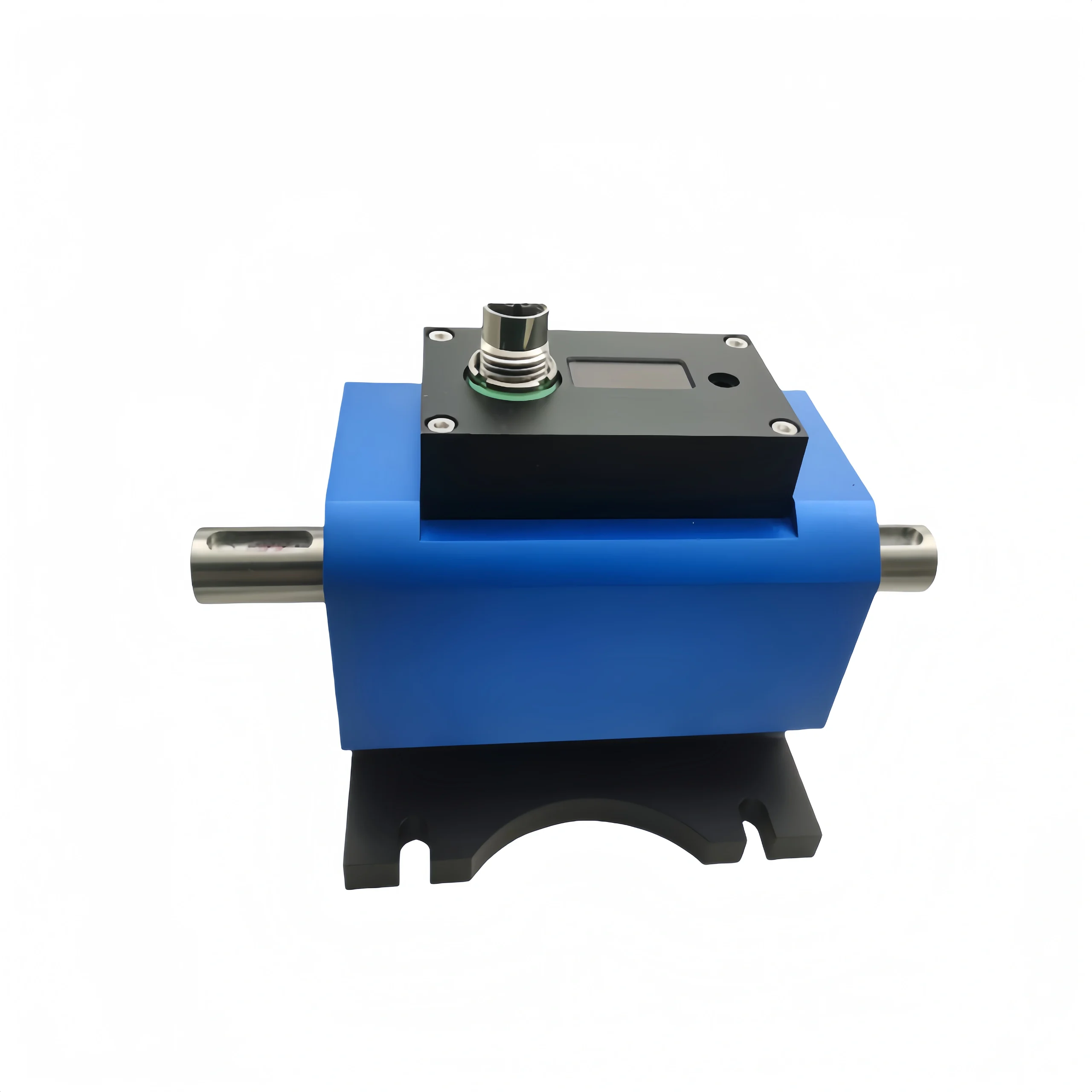
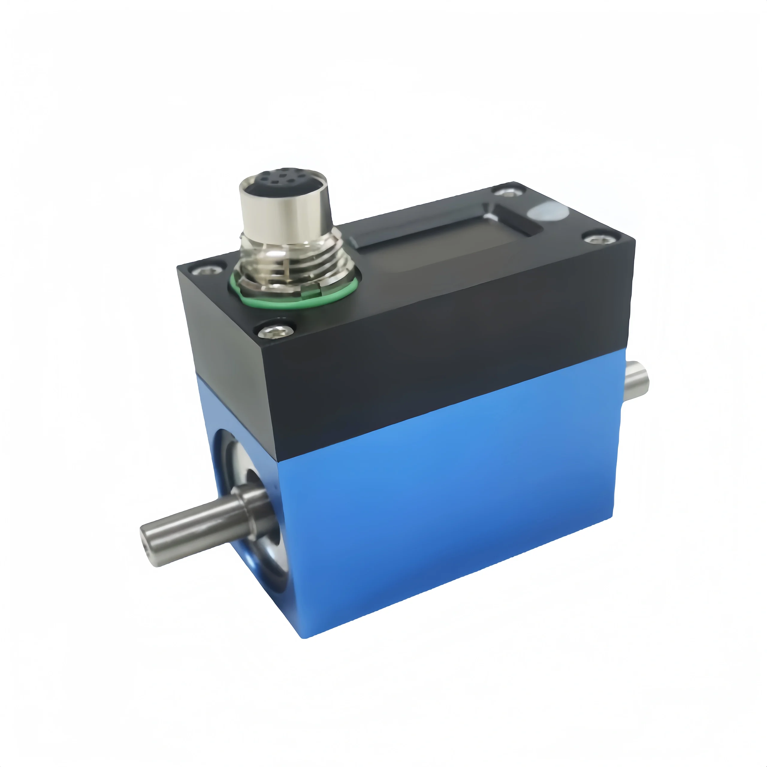
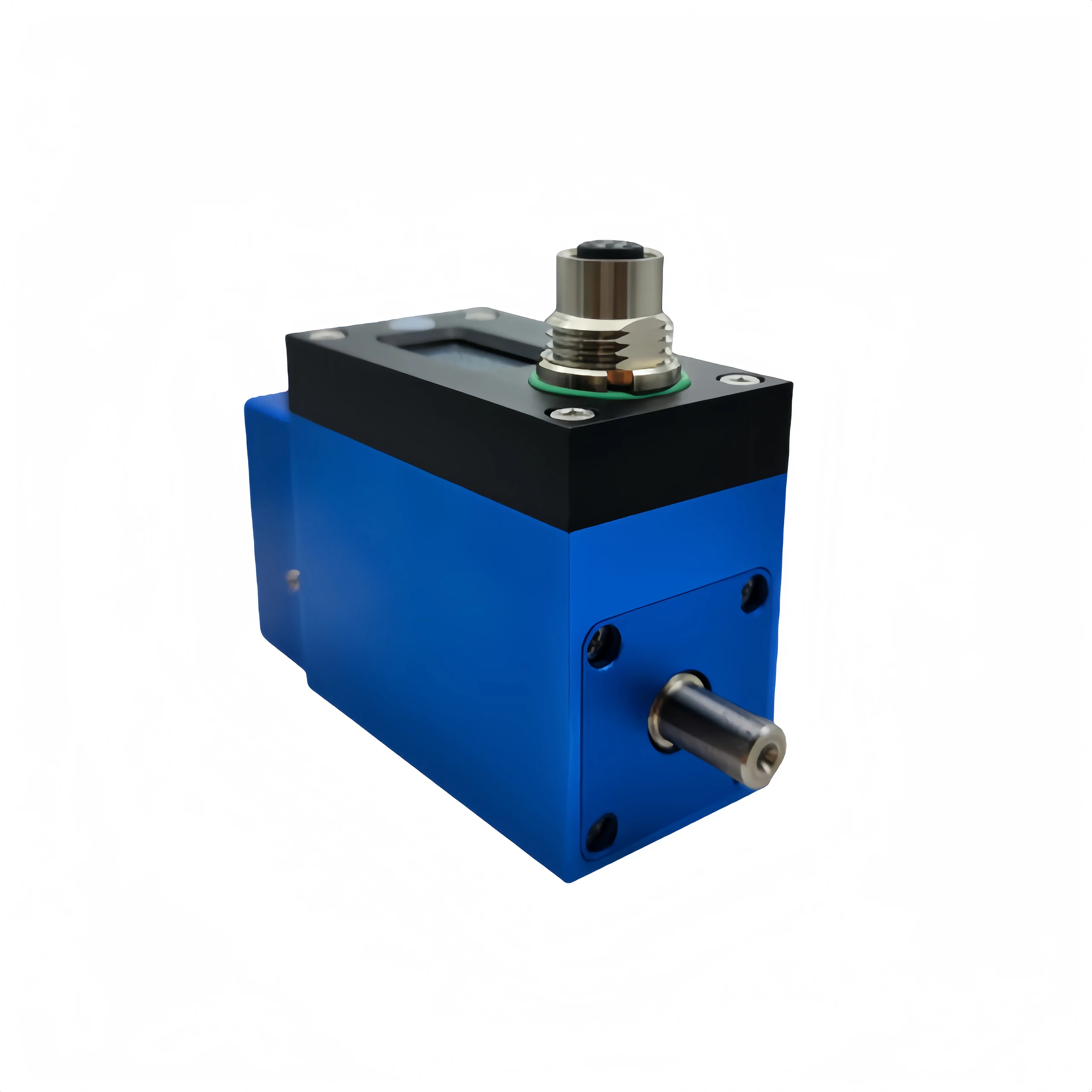
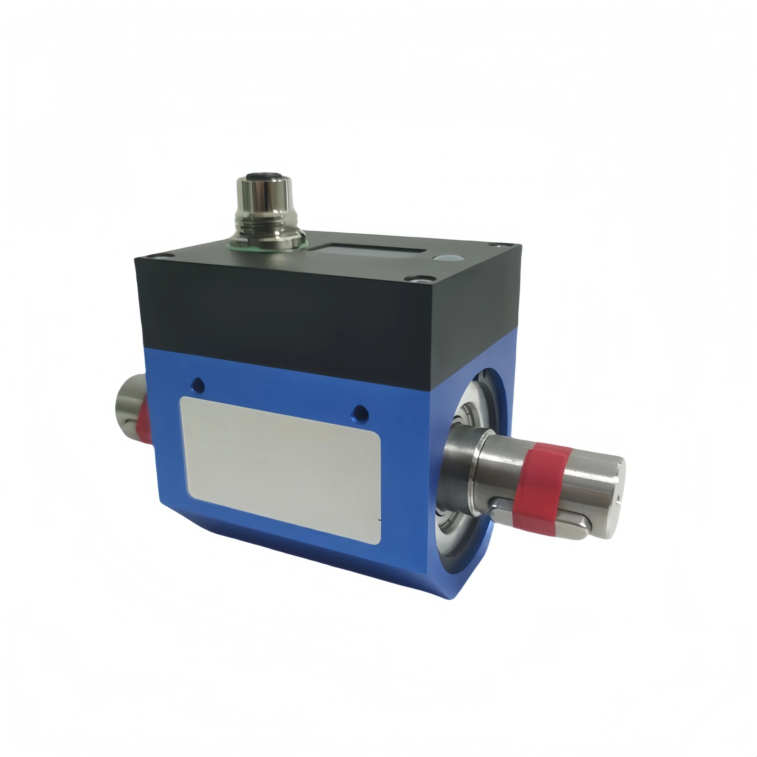
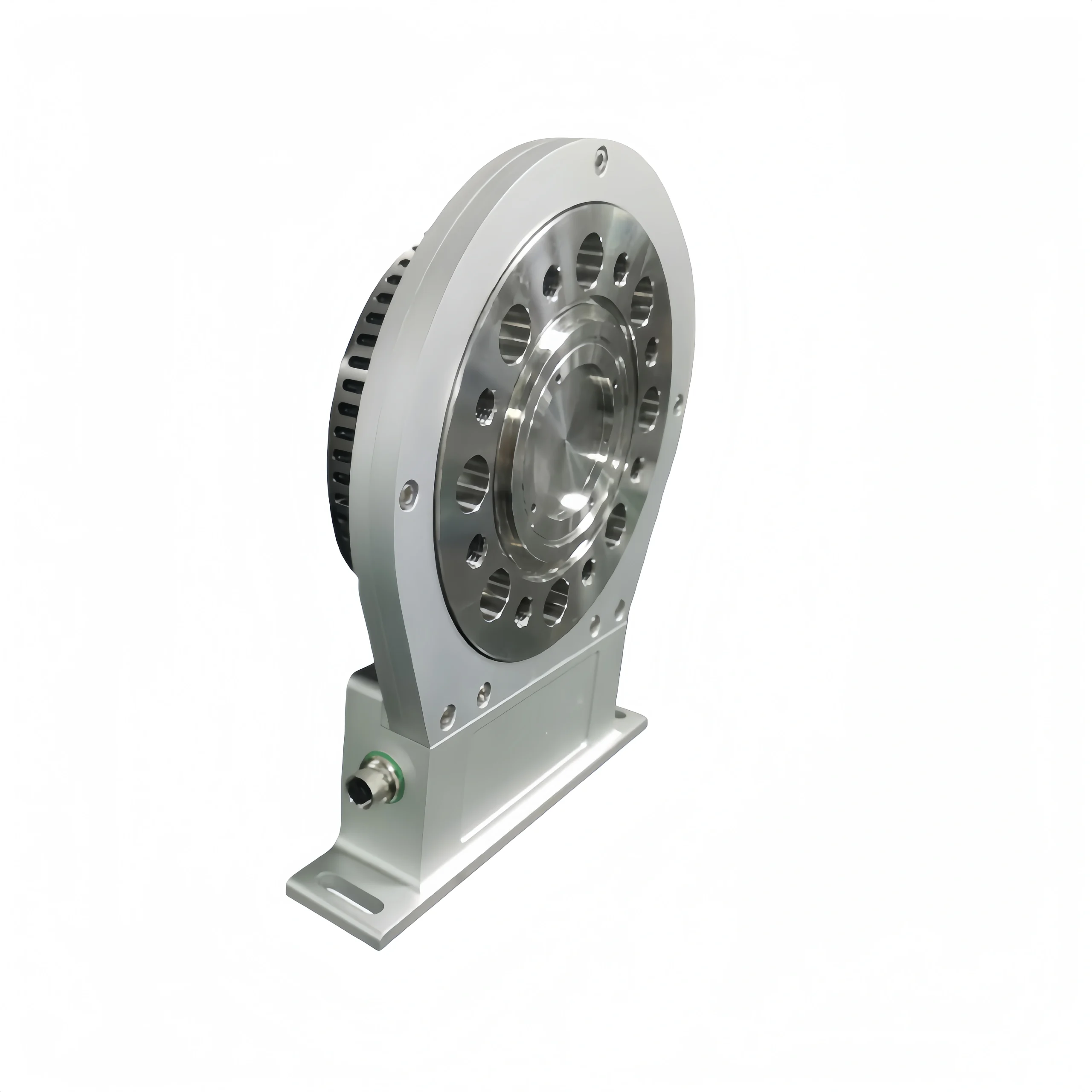
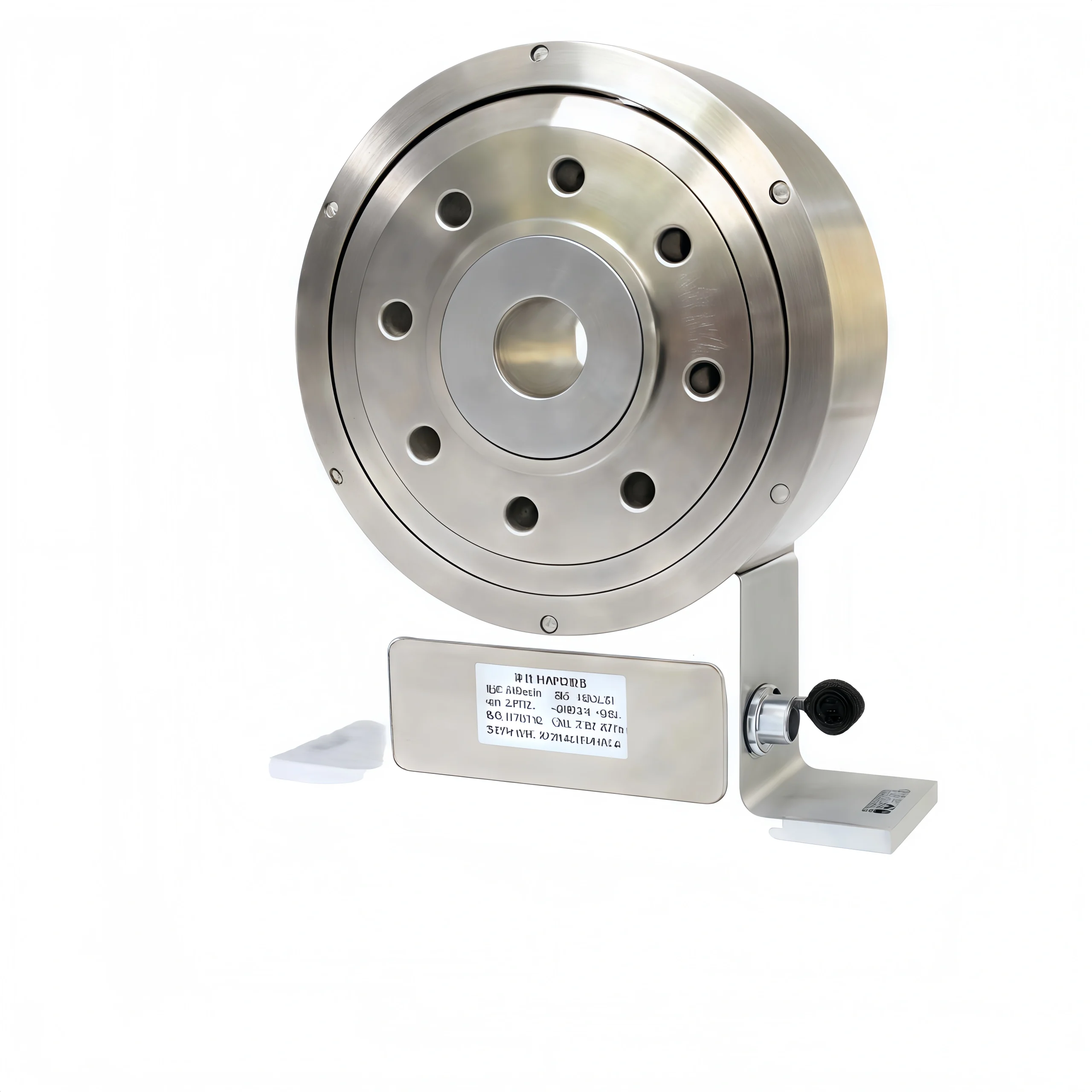
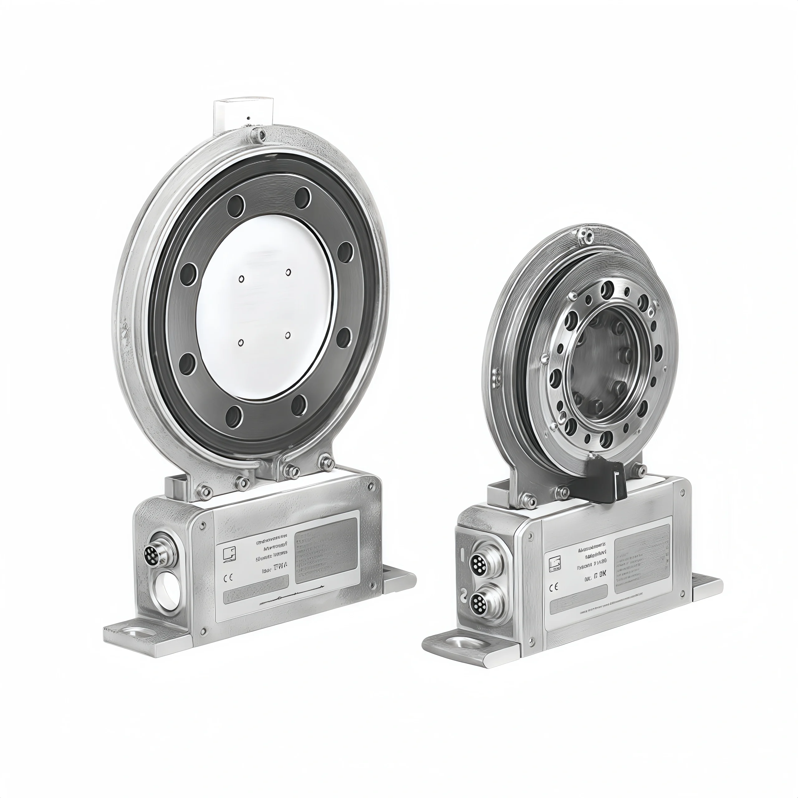
Working Principle of Disc Flange Torque Sensor:

The core components are a ring-shaped magnetic sensitive element and a magnetic ring. The magnetic ring is fixed on the rotating shaft. When the shaft rotates, the magnetic ring rotates and generates a changing magnetic field around the magnetic sensitive element. This change in magnetic field is captured by the magnetic sensitive element and converted into an electrical signal, which is then converted into a torque value by the signal processing circuit. This process is continuous, so the change in torque can be monitored in real time.

Why do We Need to Measure Torque?

Reason 1: Optimizing Fuel Efficiency (Marine Industry)

When you measure the true mechanical torque and power on the drive shaft, you can verify the true power output of the engine.

Reason 2: Load Management

Continuously monitor the material load on the equipment. Torque data also indicates whether the capacity in the equipment exceeds the capacity being used, thereby maximizing the throughput of the process. Using torque data to manage loads in industrial processes helps reduce downtime and improve operational efficiency.

Reason 3: High/Low Torque Alarm

By continuously monitoring the torque and power output of rotating equipment, you can ensure that the load remains within a safe operating range. When the load limit is triggered, the torque measurement data can signal your equipment. To shut down the equipment before a catastrophic failure occurs.

Disc Flange Torque Sensor

4: Diagnostics

By measuring torque and power, you can clearly understand the function of the equipment and the cause of the failure.

Reason 5: Predictive Maintenance

In addition to providing diagnostic capabilities for your equipment, measuring torque and power also allows you to complete preventive maintenance before major equipment failures occur, while also extending the service life of machinery.

How is Torque Calculated?

Generally, the formula for calculating torque is: Torque M = lever length r × vertical force F. The symbol is “M” and the unit is Newton meter Nm. Clockwise torque is expressed as a negative quantity and counterclockwise torque is expressed as a positive quantity.

The simplest formula for calculating torque in a motor is the vector product of the lever length and the force F applied perpendicular to the lever, that is, M = r×F.

In the actual application of motors, torque is called “driving torque”. The common formula for calculating torque is torque T = 9550×power P÷speed n, where P is the output power in kilowatts, kWn is the speed in revolutions per minute r/min.

Related Products

Related News

The function of a flow switch is to measure and control the flow of a pipeline. By monitoring the medium […]

A positive displacement flow meter is the most accurate flow meter. It is also called a fixed displacement flowmeter or […]

What is a Radar Level Transmitter? A radar level transmitter is an instrument that uses radar technology to measure the […]

About Ultrasonic Level Measurement Ultrasonic measurement is a proven and cost-effective level measurement solution for liquids and bulk solids. It […]

How to Check The Well Water Level? To check the static water level in a well, you can use a […]

Can pressure sensors measure vacuum? Yes, a pressure sensor can measure vacuum( -100KPa~0KPa). But only if it is specifically designed […]

About water pressure Water pressure is the pressure exerted by the weight of water on a unit area under the […]

What Are Mass Flow and Volume Flow? Mass flow Essentially, mass flow is the mass of a gas or liquid […]

Scroll to Top

Get A Free Quote Now !

Contact Form Demo (#3)