Turbine flow meters are also known as impeller flow meters. They can measure the flow rate of organic liquids, such as petroleum, inorganic liquids, liquefied gas, natural gas, coal gas, and low-temperature, low-viscosity fluids.
If you want to learn more about turbine flow meters, this article is worth reading.
A turbine flow meter is a velocity-type flow measurement instrument, which is used to measure the flow of liquids or gases.
Read More about: Guide for Different Types of Natural Gas Flow Meters
Pros:
- Wide turndown ratio, typically ranging from 10:1 to 20:1.1.
- High measurement accuracy, typically achieving ±0.5% to ±1.0%.
- Rapid response to flow changes, suitable for dynamic flow measurement, and capable of
promptly reflecting instantaneous flow variations. - Under stable operating conditions, multiple measurement results exhibit excellent repeatability.
Cons:
- Requires regular maintenance, including turbine cleaning and bearing lubrication, which increases operational costs.
- Fluid passing through the turbine flow meter causes some pressure loss, which may increase system energy consumption.
- Suitable for clean liquids or gases without impurities. However, it can measure non-corrosive, non-high-viscosity media without large particle impurities, causing turbine stalling or wear.
Gas turbine flow meters and liquid turbine flow meters are used in different scenarios. The following is a detailed introduction.
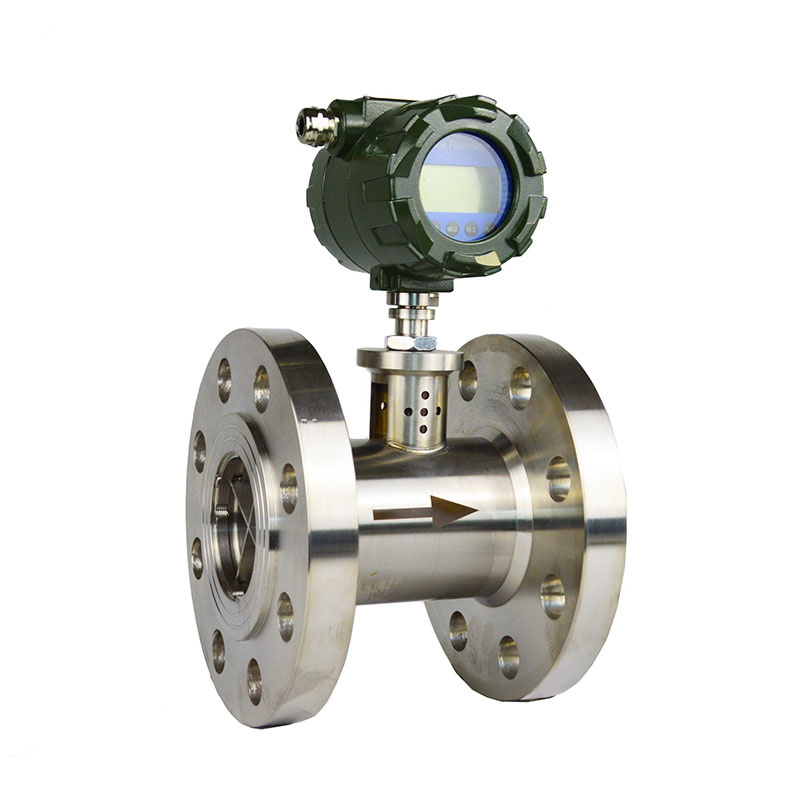
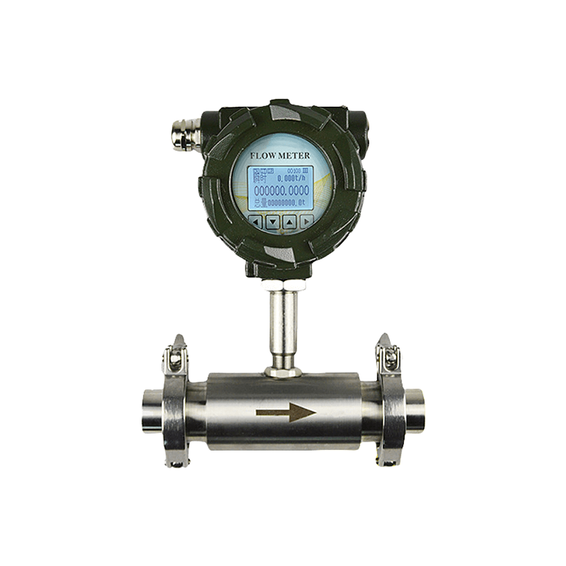
Liquid Turbine Flow Meter
Liquid Turbine Flow Meter is particularly suitable for measuring the flow rate of low-viscosity, medium-viscosity, and low impurity content liquids, such as water, emulsions, ethylene glycol mixtures, diesel fuel, and fuel oil. It can also measure low-temperature and high-temperature liquids. The following are specific application industries:
Petrochemical Industry:
It can be used to measure the flow rate of various light petroleum products, such as gasoline, kerosene, and diesel fuel.
In chemical production, it can measure the flow rate of some low-viscosity chemical raw materials, such as methanol, ethanol, and acetone.
Pharmaceutical Industry:
Precise flow control is required for various liquid raw materials and intermediate products. The pharmaceutical industry has high hygiene requirements. The turbine flow meter has a relatively simple structure. It is easy to clean and disinfect. It can meet the hygiene standards of the pharmaceutical industry.
Food and beverage industry:
For low-viscosity liquid foods, turbine flow meters can quickly and accurately measure the flow of liquids such as beer, juice, and milk. During beverage filling processes, turbine flow meters can precisely control the filling volume.
Water treatment industry:
In urban water supply and wastewater treatment processes, turbine flow meters can be used to measure the flow of wastewater and sewage.
In industrial water treatment, turbine flow meters also require real-time measurement of the dosage of various treatment chemicals.
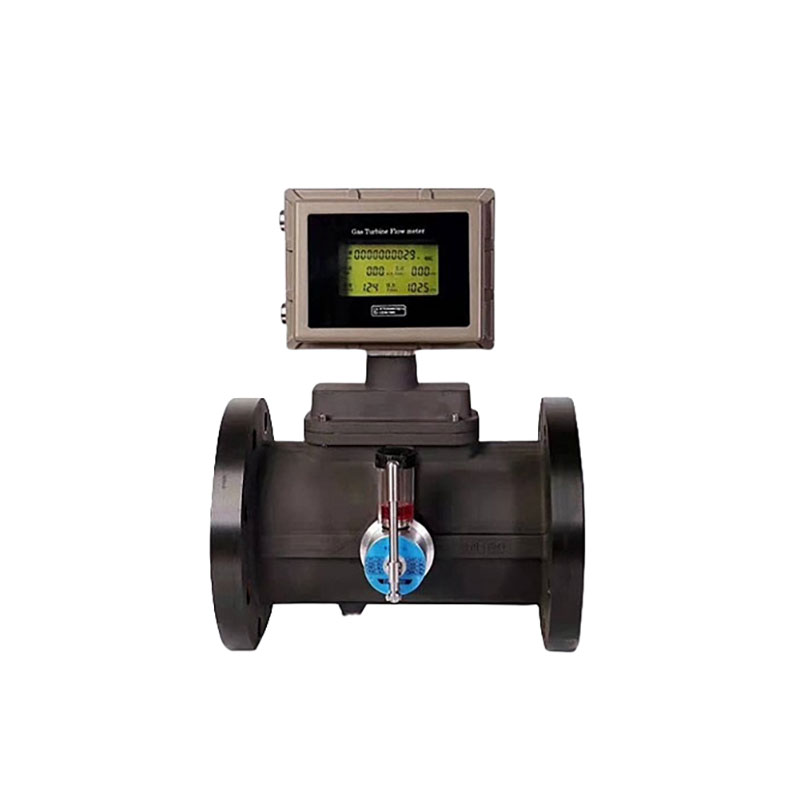
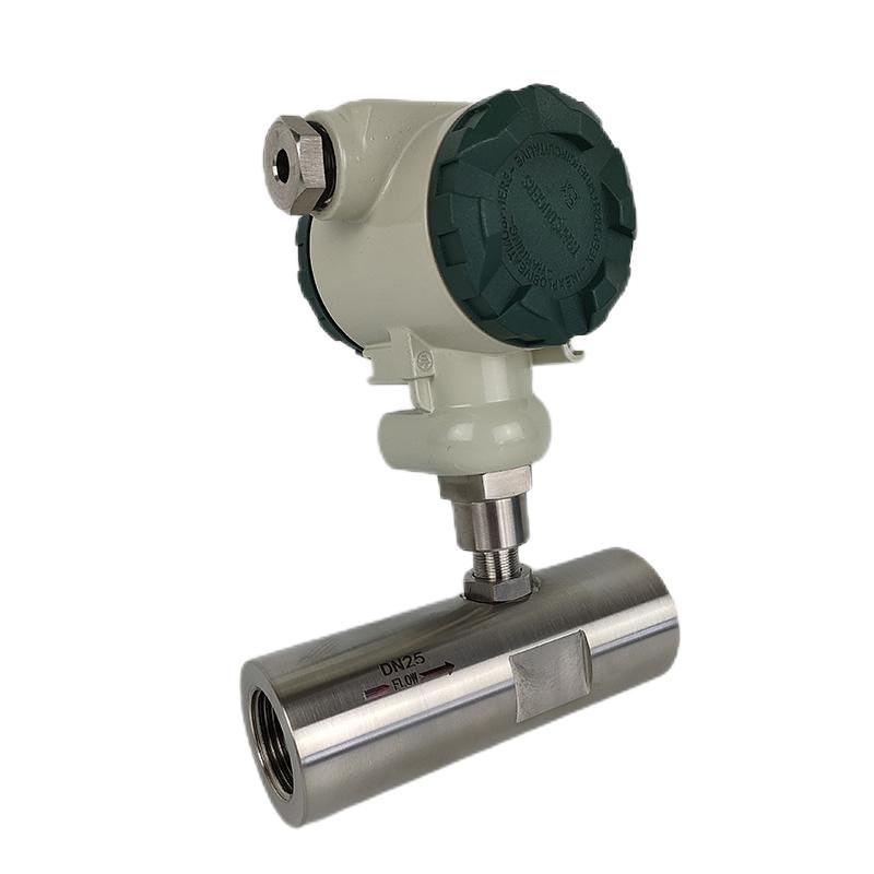
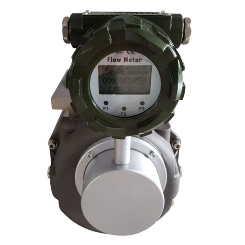
Gas Turbine Flow Meters
Gas turbine flow meters can measure the flow rate of non-corrosive gases and natural gas. The following are specific application scenarios, primarily including:
Chemical industry:
Gas turbine flow meters are used to measure the flow rate of reaction gases.
Oil and Gas Industry:
Used to measure natural gas flow rate and monitor oil and gas transportation.
HVAC systems: It measures air flow rates to ensure efficient system operation.
Energy management: In the power and heating industries, monitoring gas flow rates to optimize energy usage.
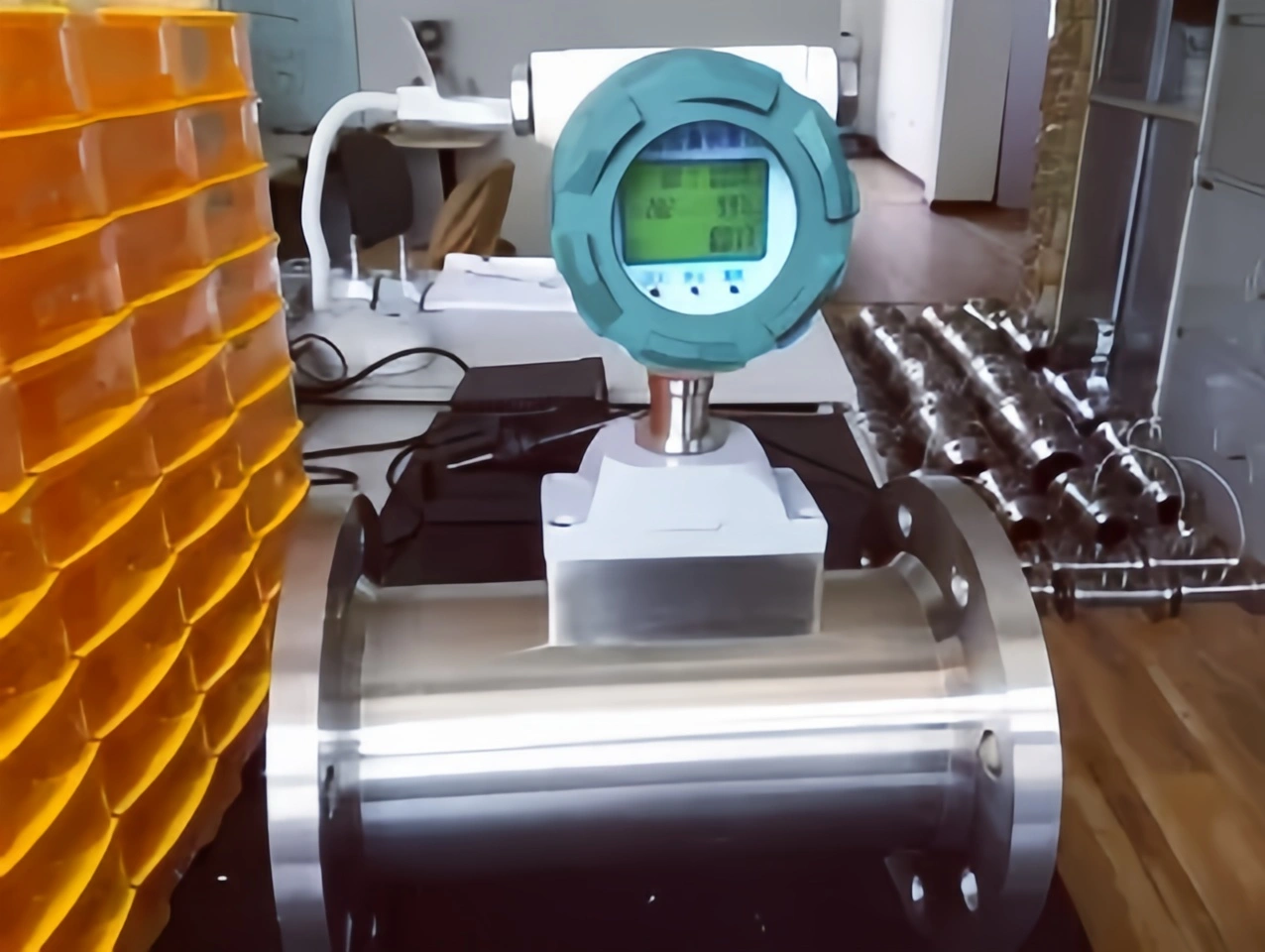
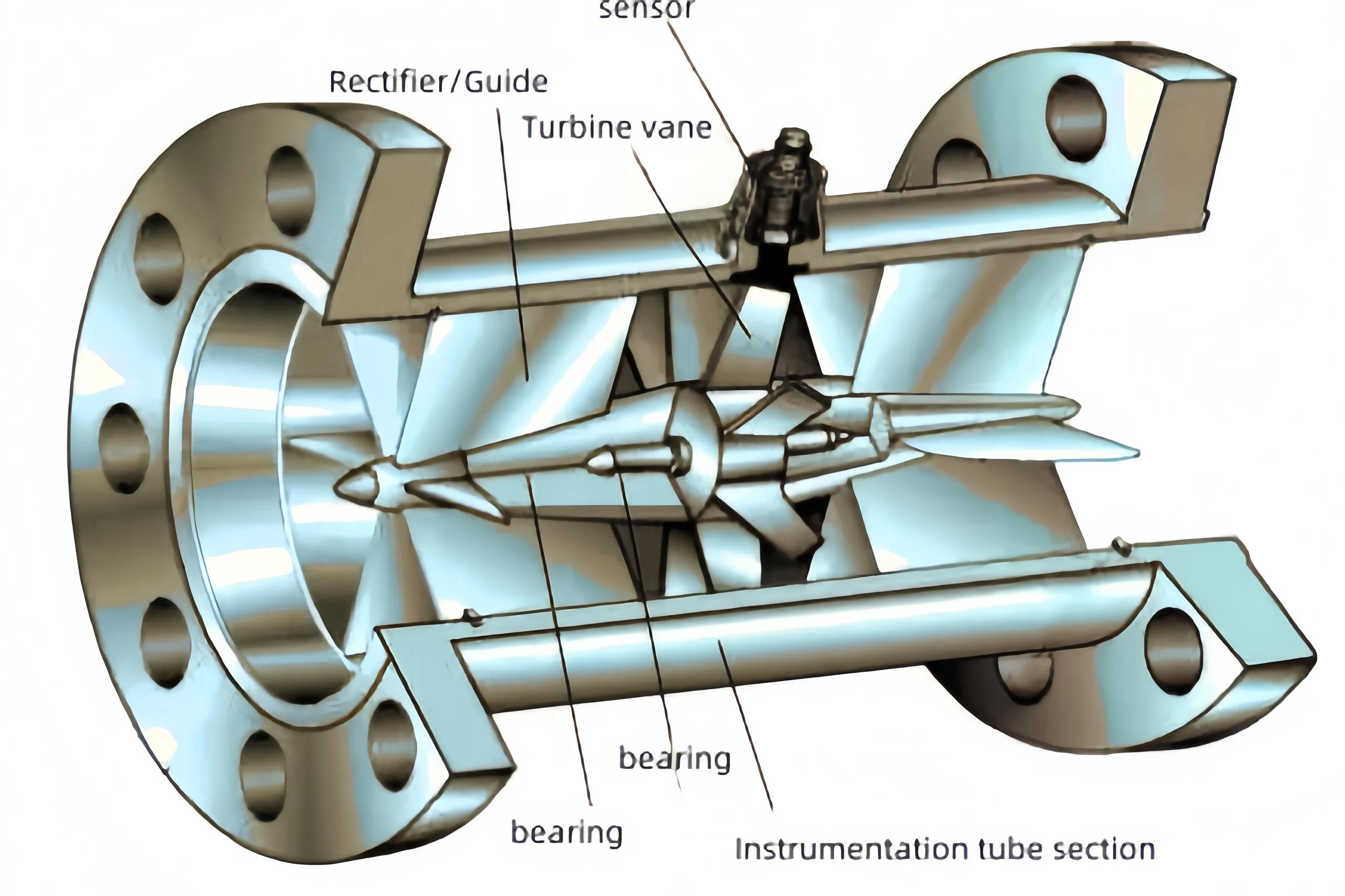
Turbine flow meters operate based on the principle of conservation of angular momentum of fluids. The fluid being measured drives the turbine blades, which cause the turbine to rotate.
Within a certain range, the rotational speed of the turbine is directly proportional to the average flow velocity of the fluid. Through a magnetic-electric conversion device, the rotational speed of the turbine is converted into an electrical pulse signal, which is then amplified and sent to the display and recording instrument, thereby enabling the calculation of the instantaneous flow rate and cumulative flow rate of the measured fluid.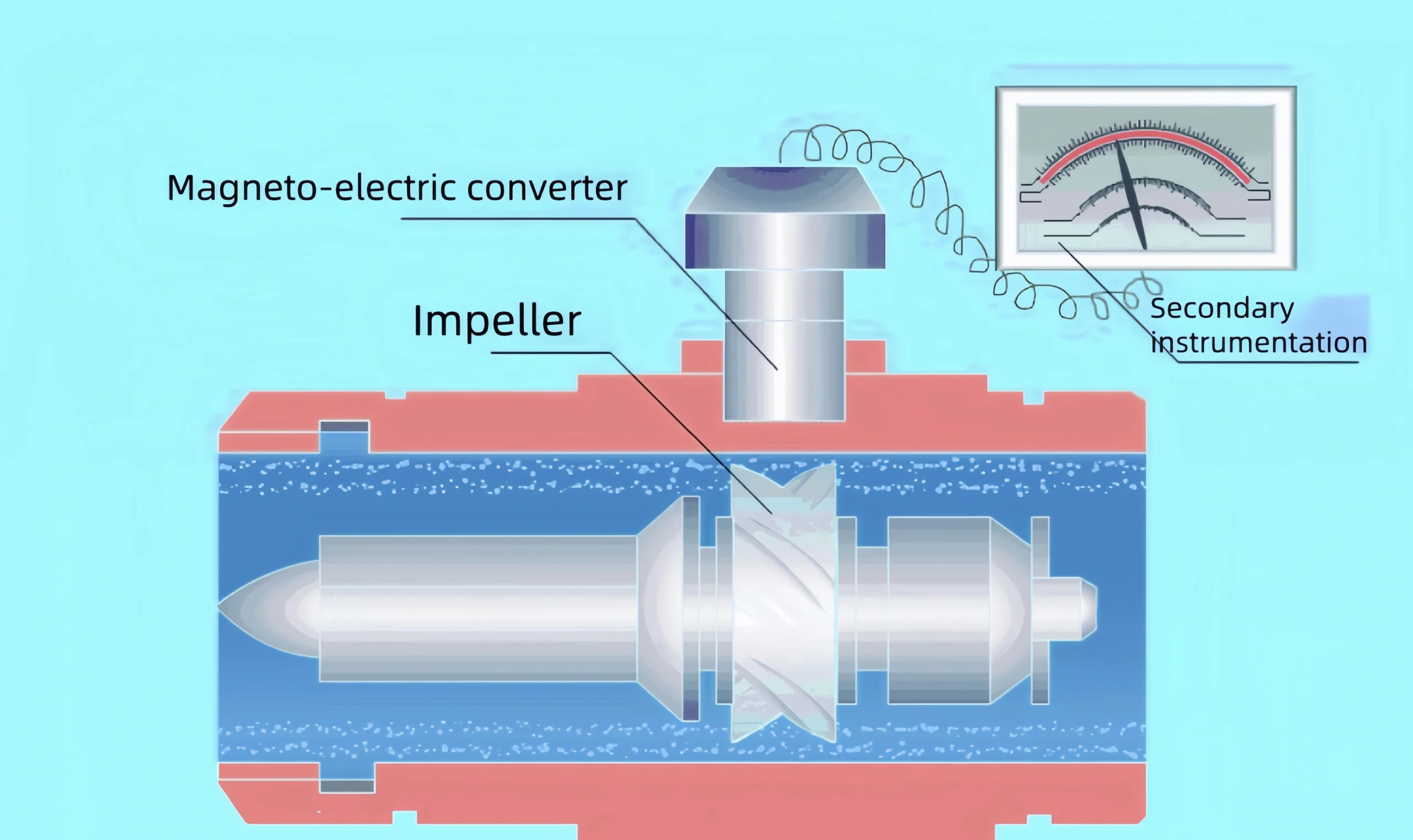
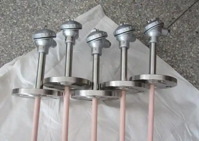
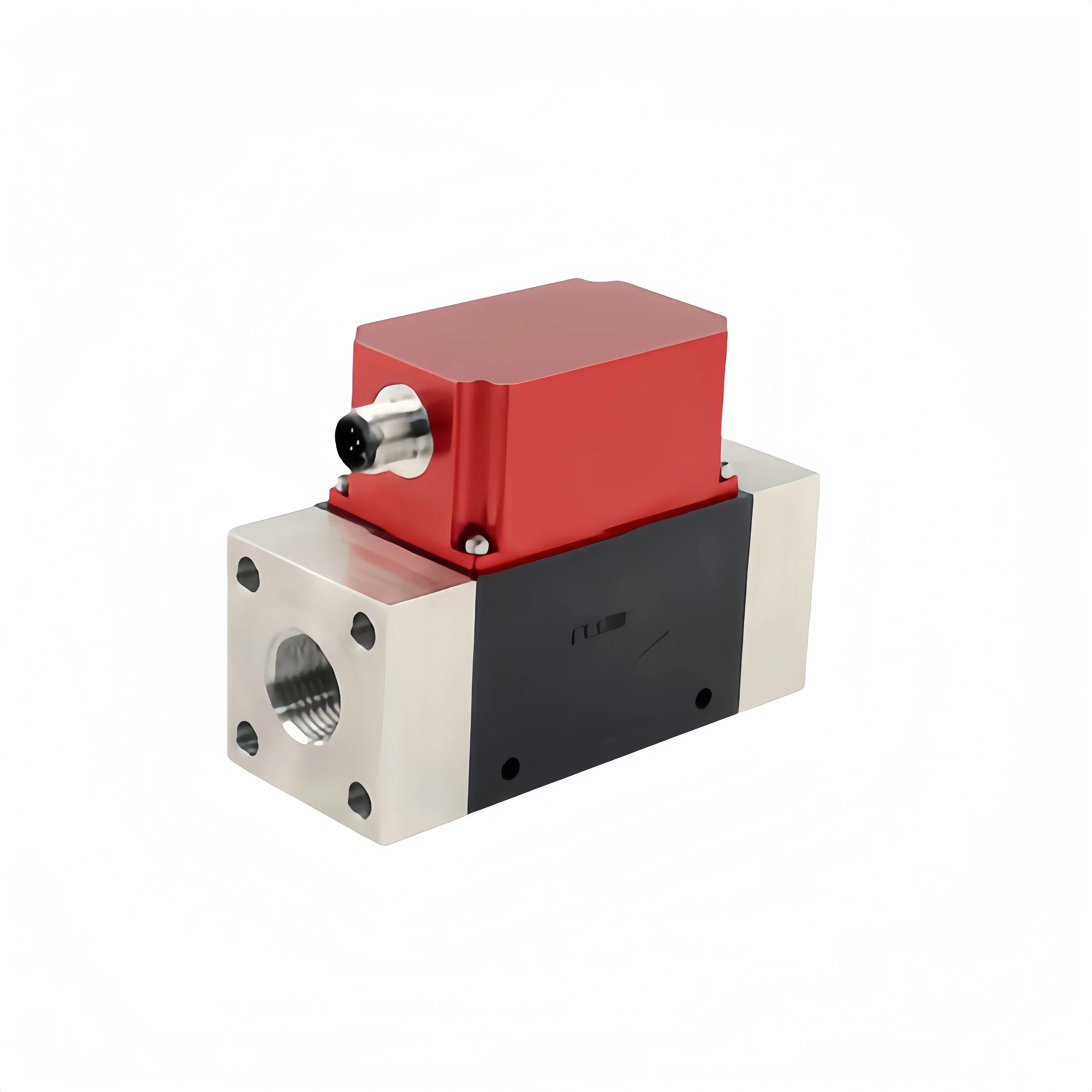
Turbine sensors can be classified into different types based on their angles. The following is a detailed classification:
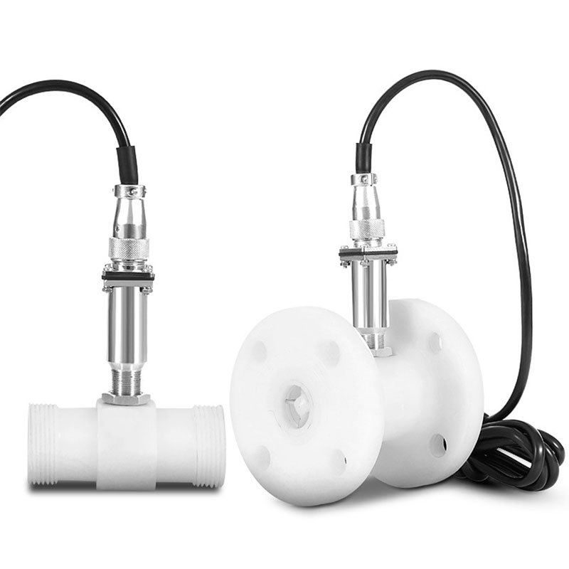
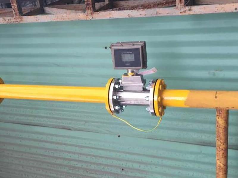
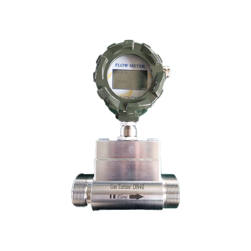
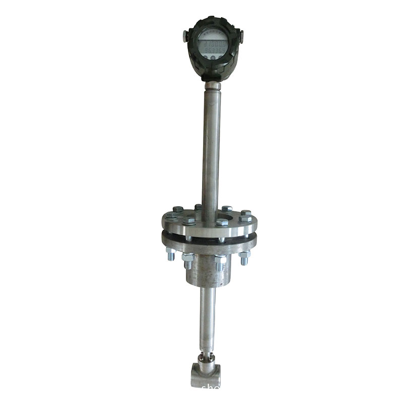
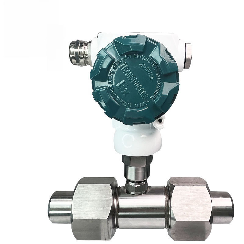
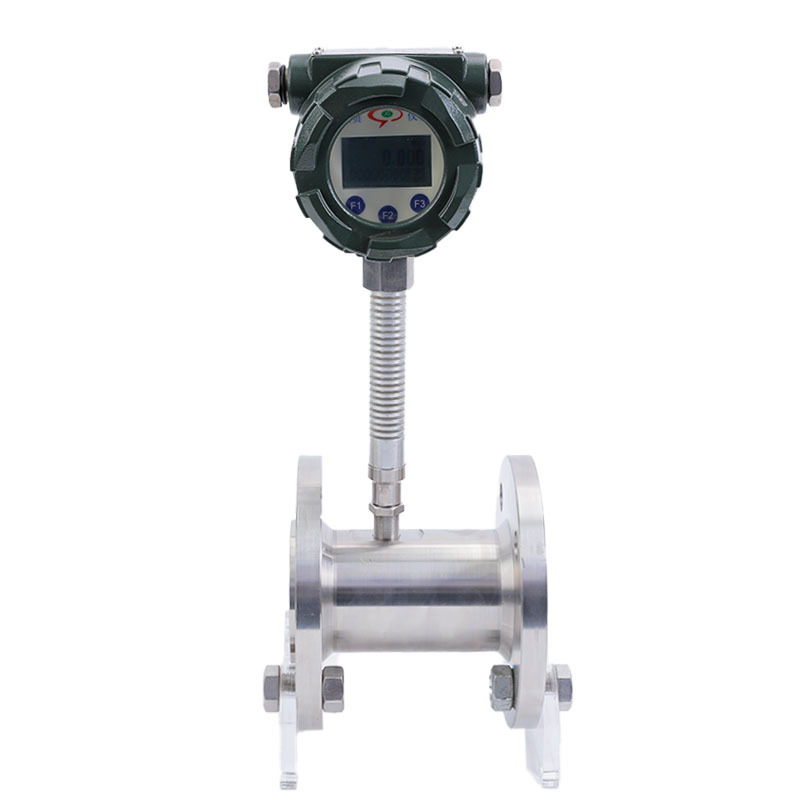
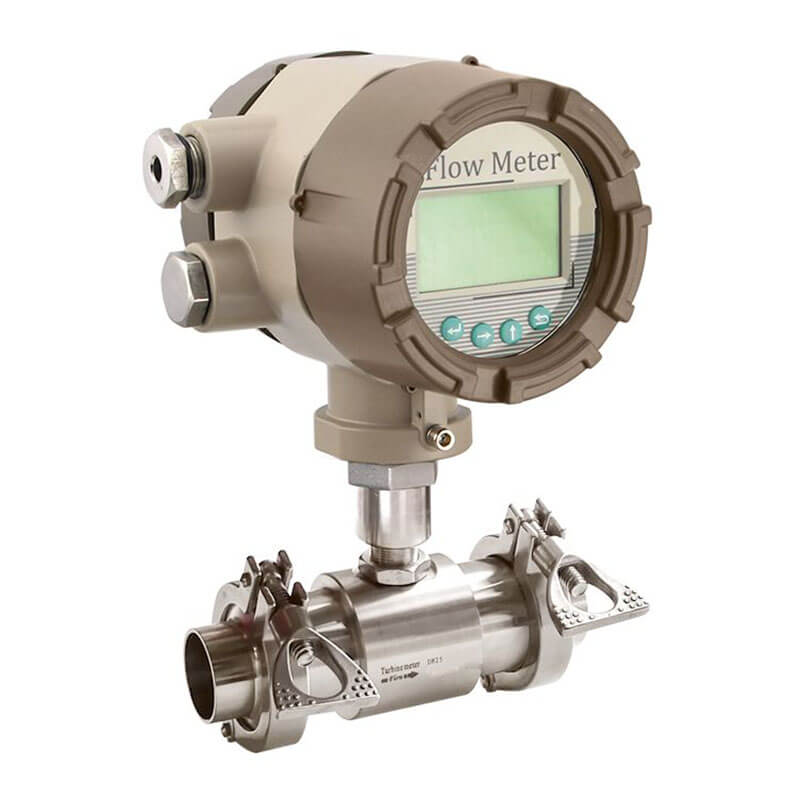
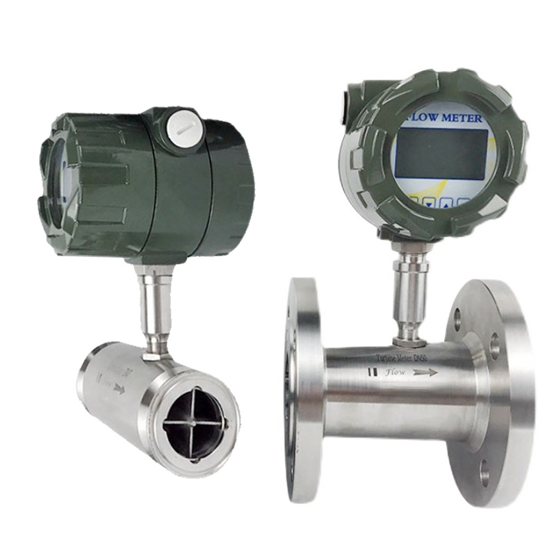
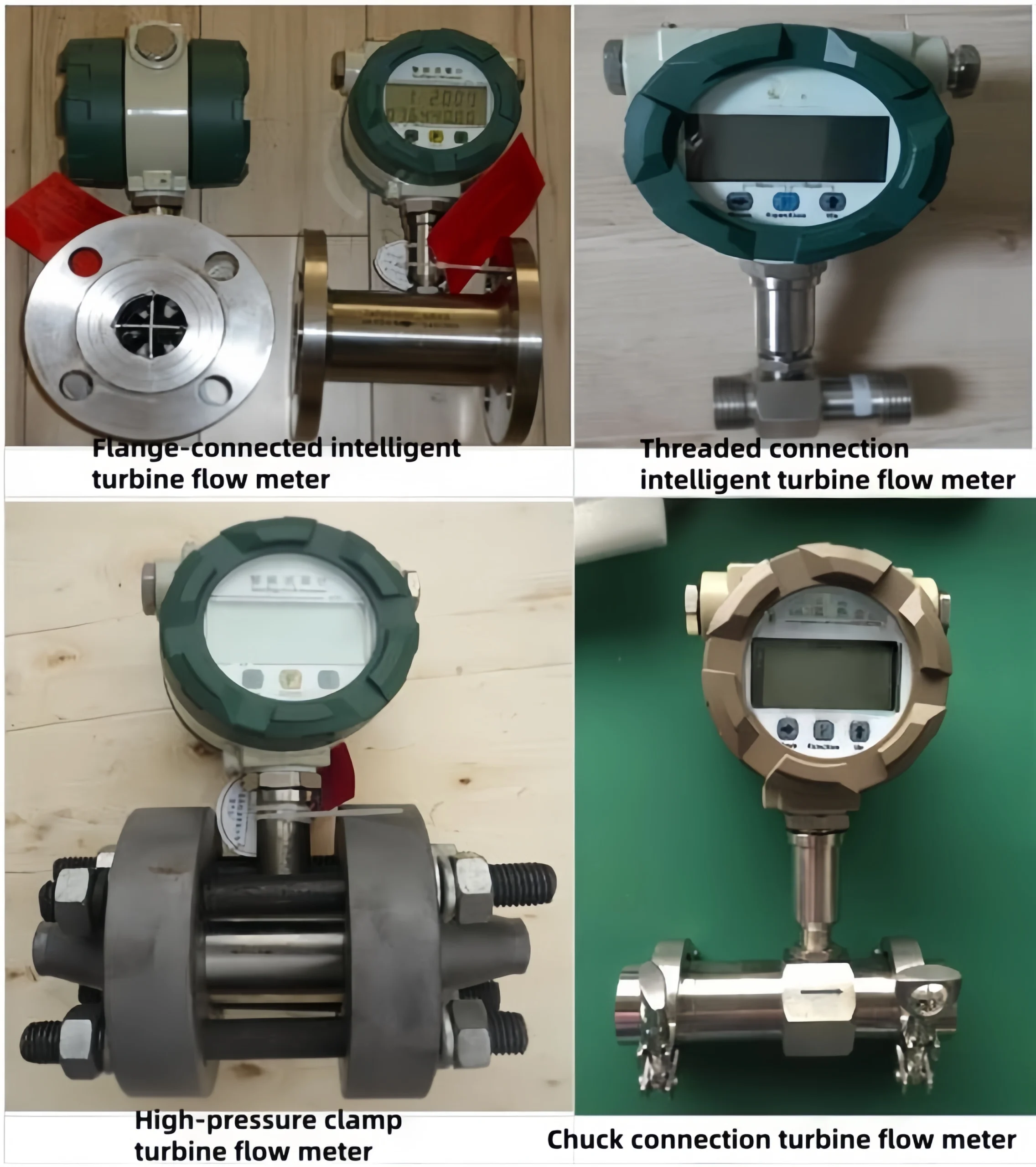
Turbine flow meters can be classified into various types based on their installation interfaces, including flanged turbine flow meters, threaded turbine flow meters, clamp-on turbine flow meters, and insertable turbine flow meters.
Turbine flow meters can also be further classified based on signal detection methods. It primarily includes inductive, variable reluctance, reed switch, and photoelectric types.
Turbine flow meters can be further classified based on different media characteristics. It includes high-temperature turbine flow meters, general turbine flow meters, low-temperature turbine flow meters, and high-pressure turbine flow meters.
Sino-Inst can customize the following parameters: General turbine flow meter: -20°C to 120°C. Low-temperature turbine flow meter: -200°C. High-temperature turbine flow meter: 160°C. High-pressure turbine flow meter: 42 MPa.
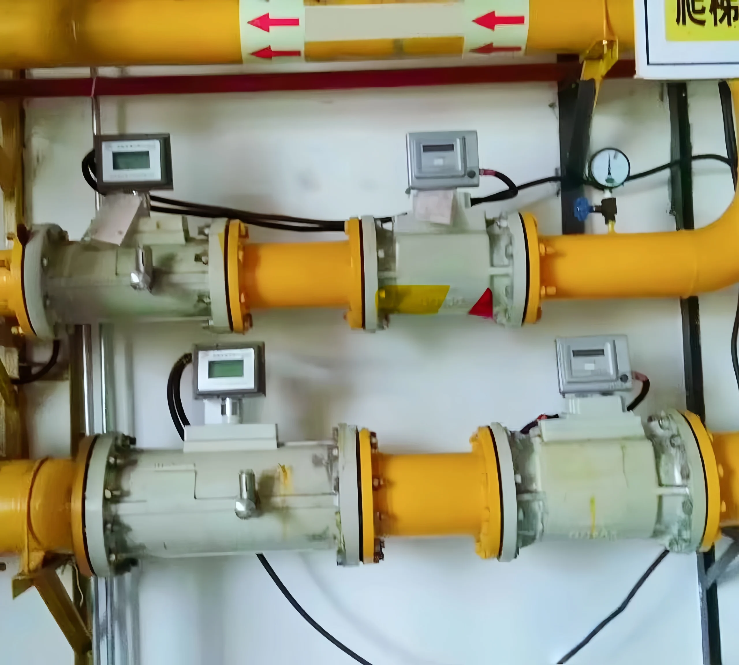
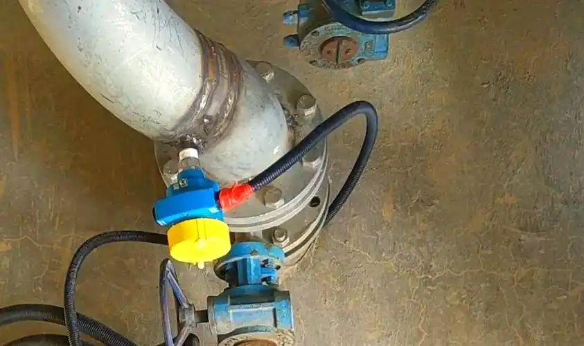
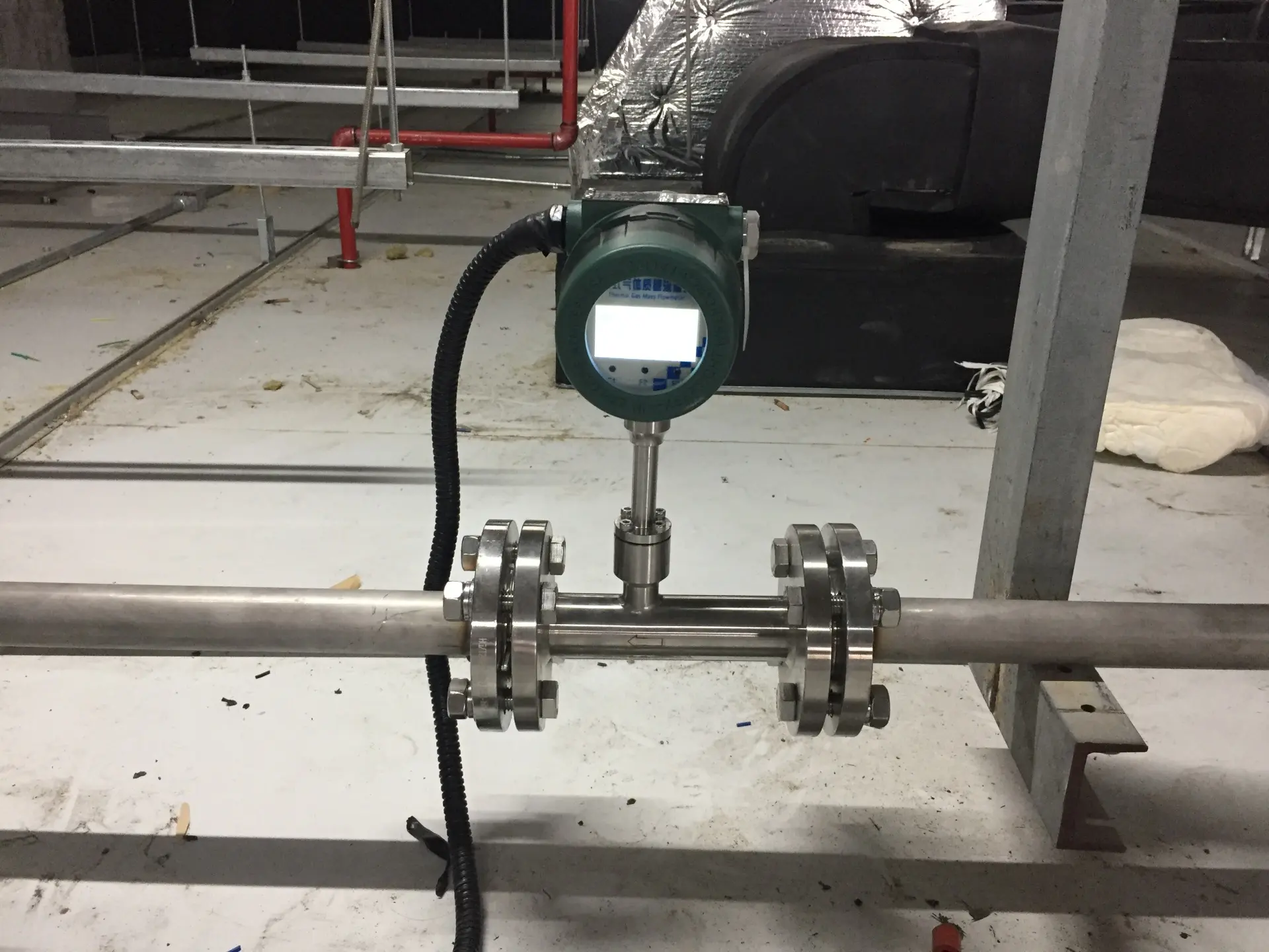
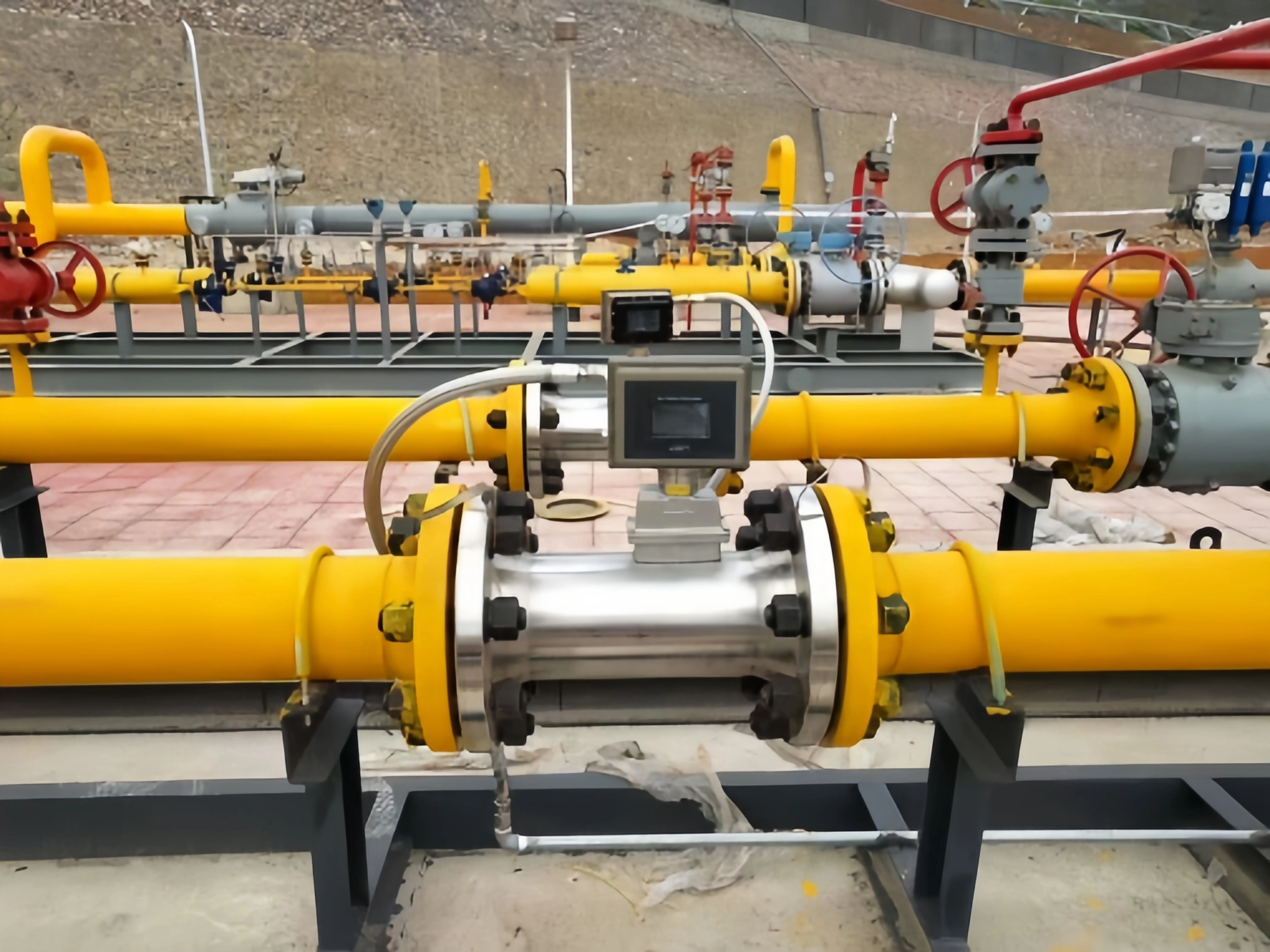
The installation of turbine flow meters on process pipelines requires special care. Based on their installation methods, turbine flow meters can be classified into in-line turbine flow meters and insertion turbine flow meters. The following are key installation points:
Pre-installation considerations:
The installation location should be as far as possible from vibration sources and electromagnetic interference sources. Ensure the pipeline is thoroughly cleaned before installation to ensure measurement accuracy.
The axis of the turbine flow meter should align with the pipeline axis. Avoid installation tilting that could affect measurement accuracy.
During installation:
The turbine flow meter must be installed horizontally. The fluid flow direction must match the arrow indication. The surrounding environmental temperature should be maintained between 20-120°C. And the relative humidity does not exceed 80%.
The inner diameter of the pipeline connected to the flow meter must match the flow meter’s nominal diameter. The straight pipe section length before the flow meter should be at least 20 times the pipe diameter. The straight pipe section length after the flow meter should be at least 15 times the pipe diameter. To optimize measurement performance.
The centerline of the process pipeline must align with the centerline of the flow meter. And there should be no protrusions at the connection points extending into the pipeline, ensure the accuracy of the pipeline cross-section and the flow field distribution at the flow meter inlet.
To smoothly control flow and minimize upstream flow field interference, control valves should be installed downstream of the flow meter. Additionally, pressure gauges can be installed separately at the inlet or outlet of the flow meter. And temperature gauges should be installed downstream.
Additionally, a flow straightener can be used to reduce the impact of upstream vortex flows and shorten the required straight pipe length. A filter should be installed upstream of the flow meter to remove impurities. When measuring the flow of volatile liquids, a degasser should be installed to remove gases from the pipeline.
When measuring the flow rate of unidirectional fluids, a check valve should be installed downstream of the flow meter. To prevent fluid backflow from affecting the flow meter’s performance.
During installation, pressure should be minimized to avoid deformation and distortion caused by thermal expansion and contraction.
If conditions permit, a bypass pipeline should be installed. To protect the startup and to avoid interrupting fluid transportation during maintenance.
For flow meters without a preamplifier, the distance between the flow meter and the preamplifier should not exceed 3-5 meters. Shielded cables should be used for signal transmission. Flow meters with a preamplifier should use four-core shielded cables to transmit output signals to the flow indicator and accumulator. Ensure proper grounding of the flow meter and ensure normal operation and safe performance.
During startup, slowly open the pipeline valves to avoid overloading the flow meter and causing damage.
Intelligent flow indicator and accumulator display instruments should be placed horizontally or installed on an instrument panel. The installation height should be determined based on ease of reading and operation.
After installation, note the following:
Turbine flow meters require regular inspection and maintenance to ensure long-term stable operation.