Gas turbine flow meters are instruments used to measure gas flow rates, and they’re used a lot in industrial, energy, and chemical sectors. Gas turbine flow meters are better than regular meters for a bunch of reasons. They’re small, they’re accurate, they’re fast, and they can handle interference really well. These features get around problems like inaccurate metering under tricky operating conditions, awkward maintenance, and poor adaptability. They can handle all sorts of gas, like natural gas, coal gas, compressed air, and inert gases. They’re great at dealing with high, medium, and low pressure, and they’re pretty affordable, too.
Principle of Gas Turbine Flow Meters
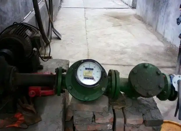
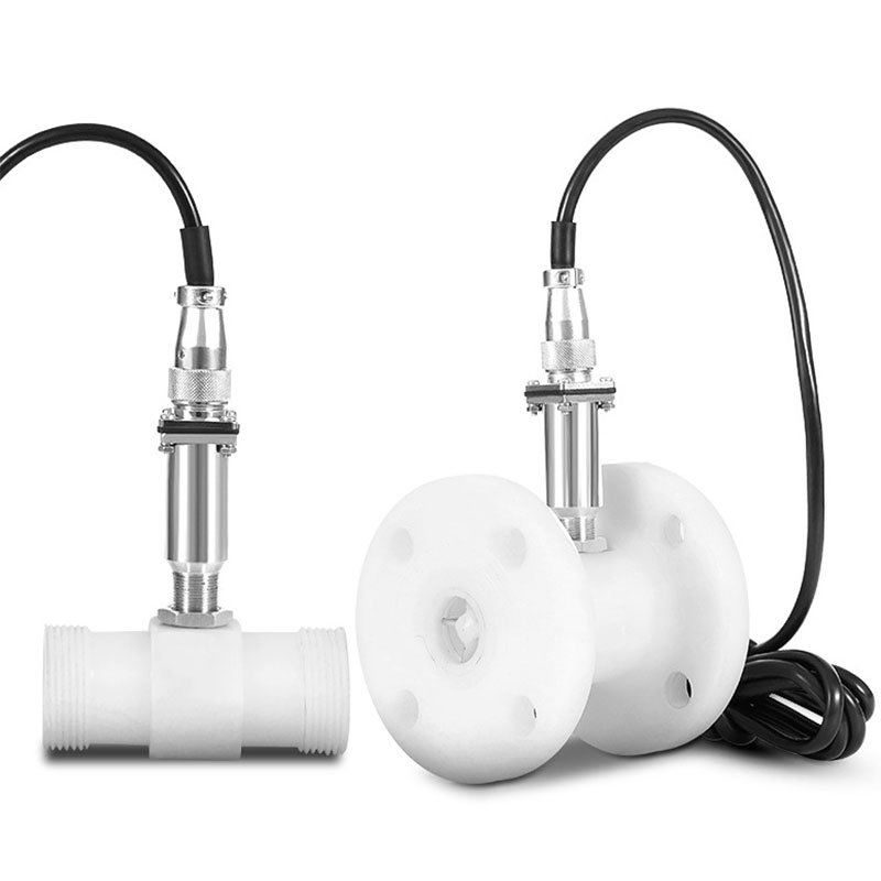
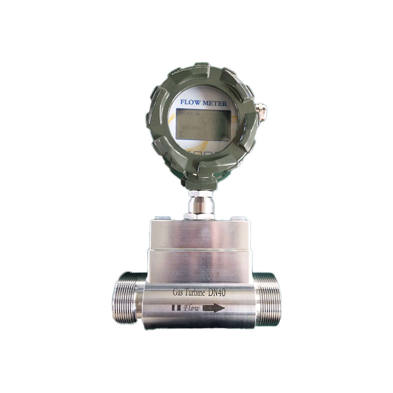
The operating principle of gas turbine flow meters is based on the relationship between turbine rotational speed and flow rate. When gas flows through the meter, its kinetic energy makes the turbine rotate. The faster the turbine spins, the more gas there is. The flow meter normally has sensors that keep an eye on the turbine’s speed and change this information into signals or other numbers that can be read to help with measuring the flow.
Specific operational sequence of the gas turbine flow meter:
Gas inflow: Gas enters the flow meter through the inlet, where the flowing gas impels the turbine to rotate.
Turbine rotation: The turbine’s rotational speed is directly proportional to the gas flow rate; higher flow results in faster turbine rotation.
Signal conversion: The turbine’s rotational speed is converted into an electrical signal via sensors (such as Hall effect sensors or photoelectric sensors).
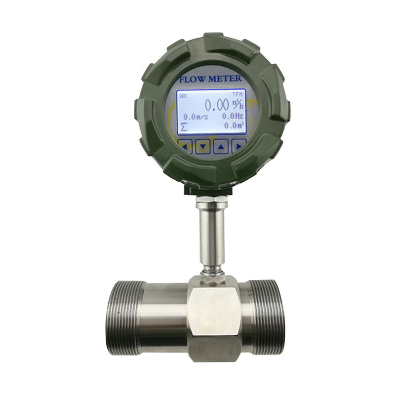
Data processing: The electrical signal is processed and displayed as the gas flow rate value.
Characteristics of Gas Turbine Flow Meters
Advantages:
High Accuracy: Accuracy classes usually range from 0.5 to 1.0, with some models achieving 0.2. This meets the standards for measuring trade, providing accurate data for both natural gas transactions and industrial energy use, and preventing losses from inaccurate measurements.
Rapid Response: Swiftly detects fluctuations in gas flow, delivering real-time feedback even during intermittent usage without lag. Ideal for dynamic flow measurement scenarios.
Low Pressure Drop: Its smooth inner design allows gas to flow easily through the pipeline and keeps the pressure steady. This prevents gas stoves from producing less heat in people’s homes and reduces energy wastage in factories.
Wide Rangeability: The standard range of turndown ratios is from 1:10 to 1:40, with some models capable of 1:100. This accommodates diverse flow requirements—from low residential flows to high industrial volumes—enabling a single instrument to cover the spectrum without frequent replacements.
Rapid response: Particularly suited for pulsating flows (e.g., engine intake measurement) and rapidly changing processes.
Digital output: Generates frequency pulse signals with strong anti-interference capability, facilitating remote transmission. Direct connection to computers or PLCs is possible without A/D conversion.
Excellent repeatability: Exceptionally high short-term repeatability makes it ideal for process control feedback signals.
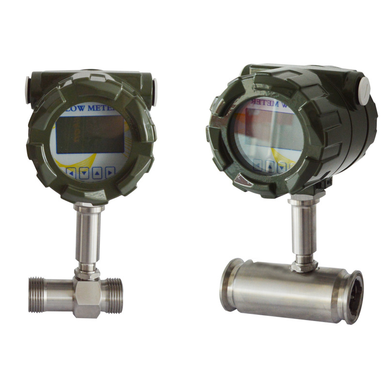
Compact design: Relatively small footprint for straightforward installation.
Disadvantages:
High cleanliness requirements for media: Particles, dust, droplets or other contaminants in gases can wear or adhere to bearings and blades, altering instrument characteristics or even seizing the turbine, leading to measurement failure. Upstream filtration is mandatory.
Significant influence from fluid properties: The instrument coefficient K of turbine flowmeters relates to gas density and viscosity. Accurate standard volume flow or mass flow requires compensation based on actual gas composition, temperature, and pressure.
Moving components present: The turbine and bearings are moving parts subject to mechanical wear. If you use it for a long time, it might not be as accurate as it should be. The standard range of turndown ratios is from 1:10 to 1:40. Some models can go as high as 1:100.
High installation requirements: To make sure that the water flows at the same speed in all directions, there are strict rules about how straight the pipe should be (usually 10D upstream and 5D downstream, where D is the pipe’s diameter). You cannot install this in places where there is a lot of vibration.
Applications of Gas Turbine Flow Meters
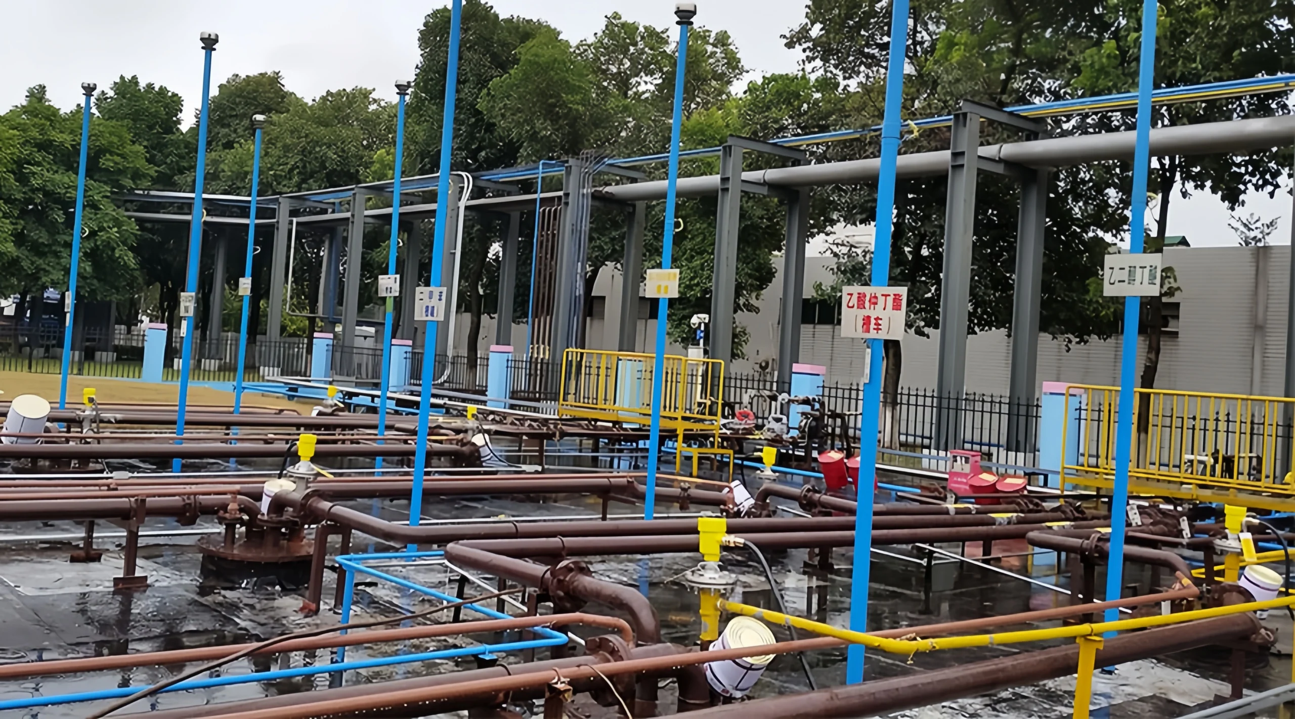
Natural Gas Sector
Gas turbine flowmeters are important to the natural gas industry. These meters are perfect for measuring gas in many different situations.
Upstream Exploration and Production: At wellheads and gathering stations, these meters quantify well output and aggregated gas flow. Designed for high-pressure environments and outdoor vibration, they furnish data for well capacity assessments.
Midstream Long-Distance Pipeline Transmission: At metering stations and provincial border transfer points within long-distance pipeline networks, large-bore, high-precision gas turbine flow meters serve as core equipment for natural gas trade settlement. Paired with temperature and pressure compensation devices, they eliminate the impact of thermal and pressure variations on measurement accuracy.
Downstream End-Use: At city gate stations, commercial/industrial users, and residential estates, instruments of varying diameters are selected for gas settlement and energy consumption accounting—e.g., small-diameter meters for residential estates and medium-diameter meters for commercial/industrial users.
Industrial Fuel Gas Measurement
Metallurgy, chemicals and coal processing are all industries that commonly use coke oven gas, blast furnace gas and liquefied petroleum gas (LPG, post-vaporisation) as fuels. After drying and removing impurities, these gases can be measured exactly using gas turbine flowmeters:
For example, in steelworks, measuring the recovery flow of blast furnace gas lets us use energy more efficiently. In chemical plants, measuring fuel gas flow controls the combustion ratios, making it more efficient and reducing energy consumption.
Industrial Metrology
Processes such as chemical synthesis, electronics manufacturing, and food processing require gases including nitrogen, oxygen, hydrogen, and argon. Accurate flow measurement of these gases directly impacts product quality:
Chemical synthesis: You can measure hydrogen and nitrogen flow to make sure you’ve got the right raw materials ratios, so your product is going to be right.
Electronics/Food: Measuring protective gases like nitrogen and argon prevents product oxidation and deterioration—e.g., nitrogen preservation in food packaging and inert gas shielding in semiconductor chip production.
Recommendations for Selecting Gas Turbine Flow Meters
Medium Compatibility
Gas Type: Suitable for clean gases such as natural gas, air, and nitrogen. Corrosive gases require special materials (e.g., 316L stainless steel, Hastelloy).
Contaminant Presence: Make sure you install a filter or use bearings that don’t need lubrication, so the blade doesn’t get stuck if there’s dust or drops in the gas.
Flow Range and Pipe Diameter
Choose a suitable nominal diameter (DN15–DN300) based on the flow conditions you are dealing with. Ensure that the flow rates are between 20% and 80% of the measurement range to maintain accuracy.
For low flow velocities (less than 2 m/s), models with low starting flow rates are recommended. If you’ve got really high flow rates, you’re going to need some custom solutions.
Operating Environment Requirements
Just pick based on industry standards and what you need for the job, and don’t go overboard trying to get super precise. For municipal gas and general industrial applications, Class 1.0 or 1.5 suffices. For very exact measurements, like in chemistry, managing energy and checking the accuracy of measurements, choose a Class 0.5 or higher to make sure the measurement is correct.
Temperature and Pressure: Standard models withstand -20°C to 80°C; high-temperature models reach 150°C. Pressure rating: 2.5 MPa. Select based on actual operating pressure.
Explosion-proof requirements: Flammable/explosive environments (e.g., natural gas stations) necessitate explosion-proof models with Ex dⅡCT6 certification.
Materials
Select equipment materials judiciously: The materials must match the medium and operating conditions, especially the casing, impeller and bearings.Cast iron or carbon steel is best for casings that deal with normal dry, clean gases.
Use stainless steel or Hastelloy for corrosive, high-temperature or high-pressure gases. Impellers should be selected based on the abrasiveness of the medium. To extend service life and reduce maintenance, bearings should be high-precision, wear-resistant types.
Functional Configuration
Signal Output: Standard pulse signal output. Optional 4-20mA or RS485 communication (supporting Modbus protocol).
Intelligent Compensation: Sensors inside the machine measure the temperature and pressure. This allows the machine to automatically adjust the flow rate to a set value.
FAQ
What are the differences in applicable media and operating conditions between gas and liquid turbine flowmeters?
Liquid Turbine Flowmeter
This is primarily suitable for clean, low-viscosity, single-phase Newtonian fluids, such as clean water, diesel, petrol, hydraulic oil and methanol. The standard operating conditions are a temperature range of -200°C to 180°C and a pressure range of 0 to 6.4 MPa. Customisable options are available for 15, 20 or 40 MPa. Suitable for pipe diameters DN4 to DN300. Strictly prohibited for use with liquids containing substantial solid particles or fibres, high viscosity (>50 mm²/s), or gas-liquid two-phase mixtures.
Gas Turbine Flow Meters
Core application: Clean, dry, low-viscosity single-phase gases such as natural gas, compressed air, nitrogen, argon, etc. Standard operating conditions: Temperature -20°C to 80°C, pressure 0 to 4.0 MPa. Suitable for pipes DN15 to DN300. Do not use this product with gases that contain liquid droplets, dust, or high humidity. Both of these need fluid that is moving smoothly and steadily.
Why must gas turbine flow meters undergo temperature and pressure compensation?
Gas volume is significantly affected by temperature and pressure. Field measurements capture the volumetric flow rate under operating conditions, whereas industrial metering or billing typically requires standardised volumetric flow rates (0°C/101.325 kPa or 20°C/101.325 kPa). Temperature and pressure compensation achieves this by continuously acquiring the medium’s temperature and pressure parameters, converting the operating flow rate to a standardised flow rate to ensure metrological accuracy.
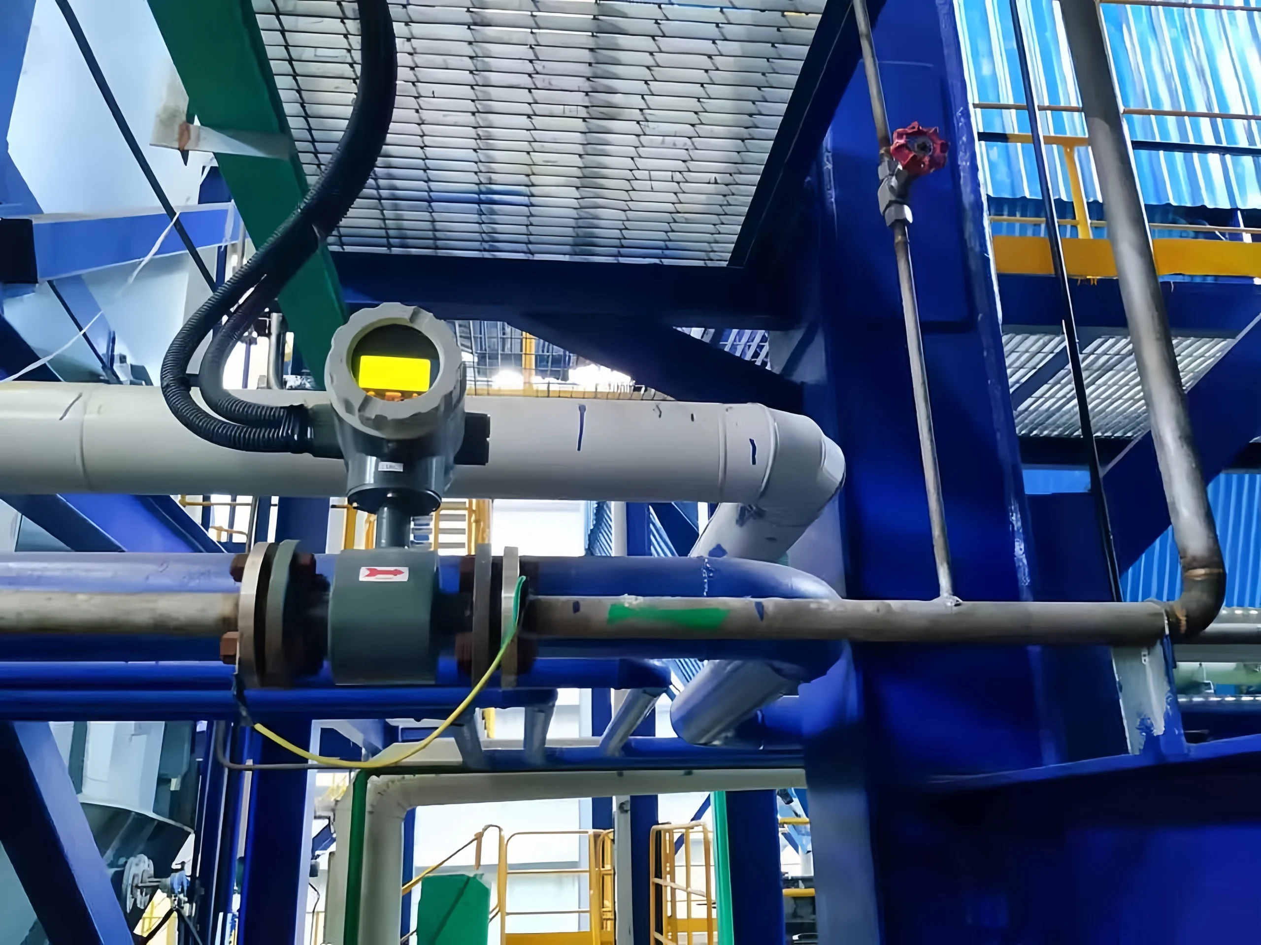
Are there specific requirements for the installation orientation of gas turbine flow meters?
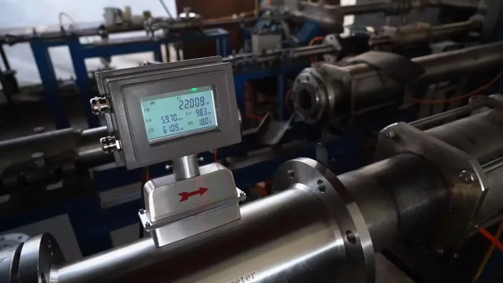
The instrument body is marked with a medium flow direction arrow. It is imperative that the medium flow direction aligns with the arrow. Reverse installation is strictly prohibited (as it may damage the turbine rotor and bearings).
Preferably install horizontally (the primary installation method) to ensure uniform force distribution on the rotor and extend bearing life;
Vertical installation is only permissible when the medium flows upwards (utilising gas thrust to drive the rotor, preventing stalling due to its own weight). Vertical installation with downward-flowing medium is strictly prohibited.
Sion-Inst has lots of experience in measuring flow. We have developed a series of gas turbine flow meters that meet strict quality standards and use advanced technology. These meters are suitable for different industries, such as chemical processing, energy, metallurgy and supplying gas to buildings. These products are very precise, very stable and can resist interference. They meet all the usual standards for measuring flows, but they also offer custom solutions to meet all your needs.