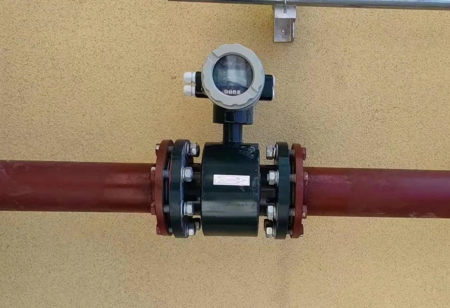
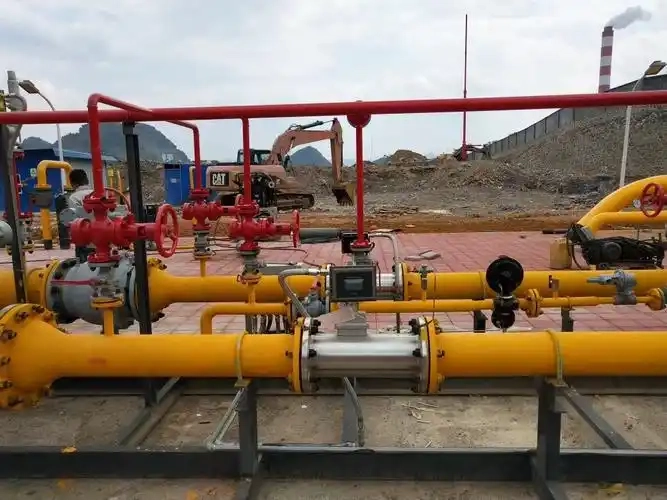
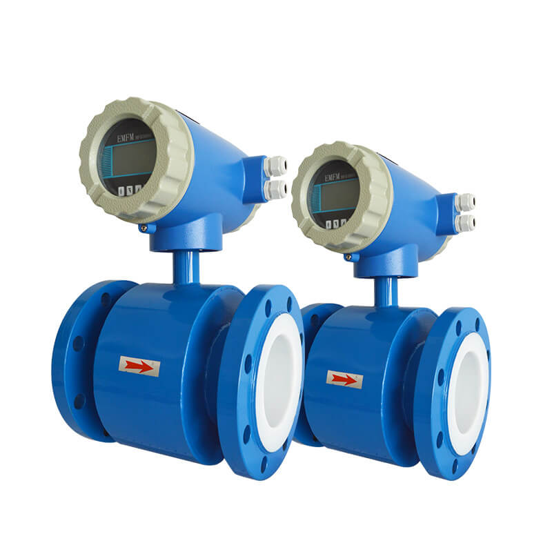
Electromagnetic flowmeters are devices that measure the flow of a liquid by using the principle of electromagnetic induction. They have certain requirements regarding the electrical environment when they are being installed and when they are in use. One of the most important things to consider is grounding, which helps to make sure that measurements are accurate and things run smoothly.
Working Principle of Electromagnetic Flowmeters
The fundamental theory underlying electromagnetic flowmeters is Faraday’s law of electromagnetic induction. When a conductor moves through a magnetic field, an induced electromotive force is generated within the conductor. Based on this principle, the volume of conductive fluid flowing within a pipe can be measured. The direction of the conductive fluid flow is perpendicular to the direction of the electromagnetic field.
An alternating magnetic field is applied perpendicular to the conduit axis, and a pair of electrodes is installed on both sides of the inner wall of the insulated-lined conduit. The connecting line between the two electrodes is perpendicular to both the conduit axis and the direction of the magnetic field. When conductive liquid flows through the conduit, it cuts the magnetic field lines, an induced electromotive force is generated across the two electrodes.
Why must electromagnetic flowmeters be properly earthed?
1.Electromagnetic flowmeters produce very small output signals, typically only a few millivolts. To enhance the instrument’s immunity to interference, the zero potential in the input circuit must be at the same potential as the earth. This constitutes a necessary condition for sensor earthing. Inadequate earthing or the absence of an earth connection can introduce external interference signals, preventing normal measurement.
2.The grounding point of the electromagnetic sensor must be electrically connected to the measured medium. This is an essential condition for the operation of the electromagnetic flowmeter. Failure to meet this requirement will prevent the sensor’s signal circuitry from functioning normally. When the fluid cuts magnetic field lines to generate flow signals, the fluid itself serves as the zero potential. One electrode generates a positive potential while the other generates a negative potential, alternating continuously. Therefore, the midpoint of the converter input (signal cable shield) must be at zero potential and electrically connected to the fluid to form a symmetrical input circuit. This midpoint is electrically connected to the measured fluid via the sensor’s output signal grounding point.
3.For steel pipe materials, standard grounding enables normal flowmeter operation. For special pipe materials such as PVC, the electromagnetic flowmeter must incorporate a grounding ring to ensure adequate grounding and proper functioning.
The Function of Grounding
Shielding External Interference
Grounding establishes an equipotential reference point, enabling instruments to effectively distinguish genuine signals from interference noise. Without grounding, electromagnetic interference from equipment such as motors, frequency converters, and pumps may mask the actual flow signal, leading to unstable readings or increased measurement errors.
Ensuring Measurement Circuit Integrity
The voltage sensed by electrodes requires a complete circuit comprising the sensor, cable, and transmitter. Grounding facilitates the establishment of a stable reference potential, ensuring unimpeded signal pathways.
Protecting Equipment Integrity
If pipelines or fluids carry an electrical charge (for example, if they contain electrolytes or are in close proximity to high-voltage equipment), grounding effectively dissipates this charge. This prevents high potentials from entering the circuit via signal lines, thereby protecting internal instrument components from damage.
Preventing Static Charge Accumulation
Certain fluid flows may generate static electricity, particularly within plastic piping or high-velocity fluid systems. Grounding facilitates the timely dissipation of static charges, thereby preventing erroneous operation.
What issues may arise from poor grounding in electromagnetic flowmeters?
Zero drift: Under static fluid conditions, the instrument exhibits zero-point deviation with irregular numerical fluctuations. After calibration, the fault recurs within a short period—this constitutes the most typical technical characteristic of inadequate grounding.
Abnormal measurement jumps and fluctuations: During stable fluid flow conditions, the instrument displays erratic measurement values that fluctuate unpredictably between high and low readings, showing significant deviation from actual process flow values.
Systematic measurement deviation: Instrument readings exhibit consistent positive or negative bias, with error magnitude increasing proportionally to flow rate.
Low-flow measurement failure: At minimal flow rates, the induced electromotive force signal operates within the microvolt range. This weak signal is easily masked by interference, resulting in no valid measurement output or zero readings.
Converter malfunctions: Stray currents infiltrating internal converter circuits overload amplification and filtering modules, triggering equipment lock-ups, fault alarms, and interruptions or distortion in 4-20mA analogue or RS485 digital signals.
Accelerated Electrode Polarisation and Corrosion: A persistent potential difference between the electrode and the measured fluid triggers irreversible electrochemical polarisation reactions. This results in the formation of a passivation layer on the electrode surface, accompanied by scaling phenomena. Simultaneously, it accelerates electrode degradation in corrosive media, significantly shortening electrode service life.
Signal Shielding Failure: Grounding failure prevents the signal cable shield from providing electromagnetic shielding, allowing external electromagnetic interference to directly couple into the signal transmission line. If you keep it running too long, it can get old and worn out, which can make it more likely to have a short circuit.
Grounding Methods for Electromagnetic Flowmeters
The grounding approach for electromagnetic flowmeters varies depending on the pipeline material.
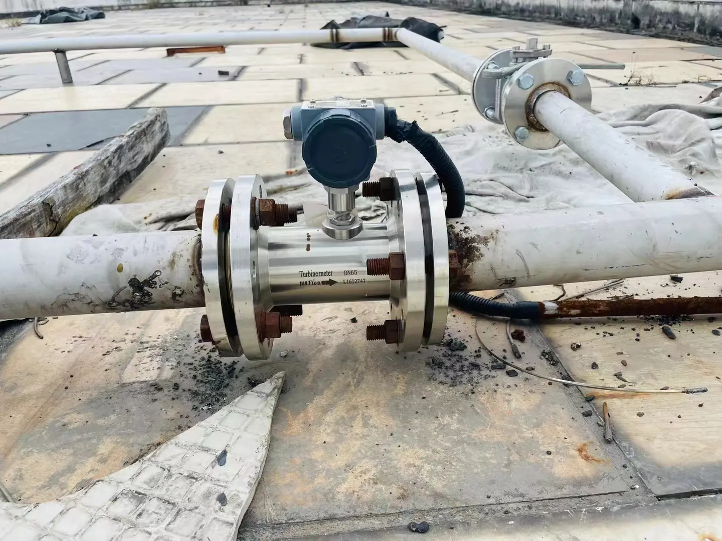
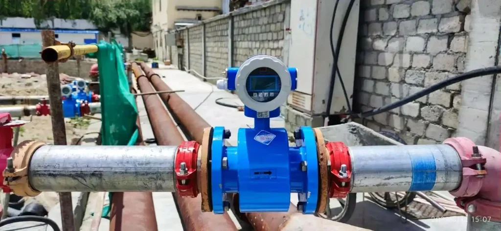
I. Metal Pipelines
If the pipeline is already earthed, the process is straightforward: the sensor flange can be bolted to the pipeline to establish electrical continuity. In such cases, no additional grounding ring is required. Simply connect the sensor flange to the pipeline using a jumper wire, ensuring electrical continuity and integrity. Then, connect the flow meter’s own ground terminal separately to the grounding electrode. This ensures reliable grounding.
If the pipeline is not grounded, a grounding electrode or grounding ring must be installed near the sensor. A separate wire must be run to the grounding grid; it must not share the grounding with other equipment to avoid interference.
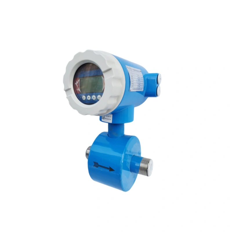
II. Non-metallic Piping
Non-metallic piping lacks inherent conductivity, necessitating supplementary grounding accessories. Three common approaches exist, selectable based on operational conditions:
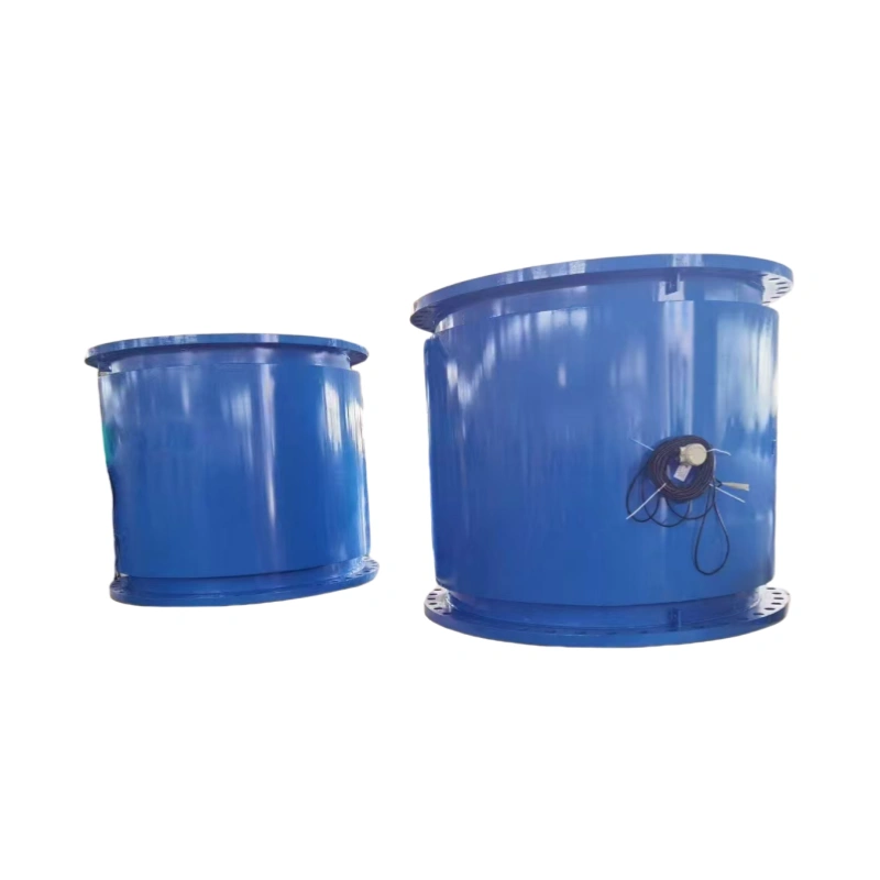
1. Grounding Ring Installation
Where the measuring pipe features a lining, grounding rings should be fitted to both end flanges. The purpose of this is to establish the conductive liquid securely as the reference point for differential potential signals. Connect it to the signal terminal of the converter to ensure that the potential between the liquid and the equipment remains consistent, thus stabilising the measurement signal.
The material of the grounding ring must be carefully considered. It is best to use the same or a similar material to the electrode to prevent corrosion by the medium, which could affect its service life. There are also various styles, with three being the most commonly used: the standard type resembles an orifice plate with a handle, simple and practical; the protective type can be fixed to flanges to prevent damage to the flange lining; for highly abrasive media, such as those containing particulate impurities, a necked protective ring should be selected to specifically shield the lining from wear.
2. Employing Grounding Electrodes (Three-Electrode Method)
If the liquid is really corrosive, the electrodes of electromagnetic flowmeters need to be made from precious metals like tantalum, titanium, or platinum. In cases like this, installing a grounding ring—which has to be made of the same material as the electrodes, as per the specs—would end up costing way too much.
To reduce expenses without compromising effectiveness, employ the three-electrode grounding method: locate the lowest point perpendicular to the measuring electrodes on the sensor’s measuring tube and install an additional electrode. This electrode, identical in material and size to the measuring electrodes, serves the grounding function, offering excellent cost-effectiveness.
3. Virtual Grounding
Thanks to new technology, virtual grounding is now being used by many people. Its principle is straightforward: it uses an input amplifier and an optocoupler in the circuit to create isolation. This means that the measurement circuit can be made to float with the liquid’s potential. The circuit will only detect a voltage signal when conductive liquid flows through the sensor at a certain speed.
The foremost advantage of this approach lies in its simplicity and cost-effectiveness. The sensor operates reliably with only its own grounding, eliminating the need for additional grounding rings or third electrodes. This streamlined installation process reduces maintenance requirements, making it well-suited for numerous routine operating conditions.
Grounding Requirements for Electromagnetic Flowmeters
1.Sensors and converters must be individually earthed. Under no circumstances should they be connected to motors or process piping. Grounding resistance should be less than 10 ohms.
2.The sensor needs to be earthed. This means that the measuring tube, housing, shielding cable, converter and secondary instrumentation must all be earthed.
3.Ground the sensor and converter locally. Ground the shielding layer of the cable to the secondary instrument at the control room end. Avoid multiple grounding points to prevent interference caused by potential differences.
4.When you’re installing sensors on metal pipelines, make sure you connect the sensor’s grounding conductor to the pipeline flange, just like the manufacturer says to, and you’ll have yourself a reliable grounding loop. The instrument’s grounding point must be an independent grounding point and must not share the grounding of other electrical equipment.
5.In locations with high electric fields, shielding measures may be implemented. However, measurement cannot be shielded; therefore, electromagnetic flowmeters must be installed away from strong magnetic fields.
As a specialist service provider with in-depth knowledge of the sensor sector, Sion-Inst prioritises technical compliance, product stability and standardised services. We deliver high-quality electromagnetic flowmeters and comprehensive solutions to clients across diverse industries.
Our ethos is all about ‘Empowering through Expertise, Collaborating with Integrity’ and we’ve got dedicated commercial and technical liaison teams to deal with client enquiries quickly, get solutions up and running, deliver equipment and provide post-installation support. We’re excited to work more closely with you, make sure we’re totally in sync with your needs, and give your business a boost with top-notch products and services.