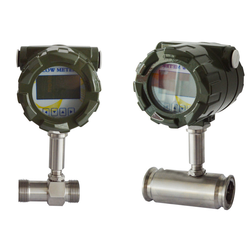
Turbine flow meters can output two types of signal: current and frequency. These represent their two main characteristics. Turbine flow meters usually convert flow into electrical signals, with each signal matching a certain volume of fluid. The frequency of these electrical pulses depends on the flow rate, so the higher the flow rate, the higher the pulse frequency.
This makes the turbine flowmeter a vital tool for measuring flow. The way it works is that when there’s more flow, the turbine spins faster, which creates an electrical signal. However, not all turbine flowmeters function in this manner. Under certain specialised conditions, they may also convert flow into a standard current signal output. In such instances, the output current remains proportional to flow velocity; a higher current indicates a greater flow rate.
Turbine flow meters are signal output types
1. Pulse/frequency output signal
The most common signal output for turbine flow meters is a frequency signal, where the output frequency is directly proportional to the volumetric flow rate of the fluid. Usually, the frequency signal output is a square wave signal, showing a linear relationship between frequency and fluid flow rate. The two main uses of frequency signals are equipment control and data logging.
2. Analogue Output Signal
Turbine flowmeters can also send out analogue signals, typically in the form of current or voltage. The strength of the output depends on the speed of the flowing fluid. These signals can be connected directly to other equipment, such as computers, controllers or data gathering systems. The standard output range for analogue signals is 4 mA to 20 mA for current signals, and 0 V to 10 V for voltage signals. This enables you to monitor and control flow variations via the analogue output.
3. Digital Output Signals
Turbine flow meters can also send digital signals. Fieldbus protocols such as Modbus RTU are commonly employed to transmit flow values for this type of indication. In industrial control systems, flow values can be accessed by decoding digital outputs. This makes the values more reliable and enables you to monitor and control them remotely.
Signal output types available from Sion-Inst
N | Pulse output direct outlet the signal line: +12~24V, Pulse output,High level≥8V Low level≤0.8V
|
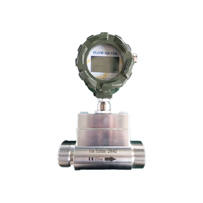
A | Explosion proof head, no display: three wire pulse output, two wire system 4 ~ 20mA output, three wire voltage output optional
|
A1 | Hesman joint, no display: three wire pulse output, two wire system 4 ~ 20mA output, three wire voltage output optional
|
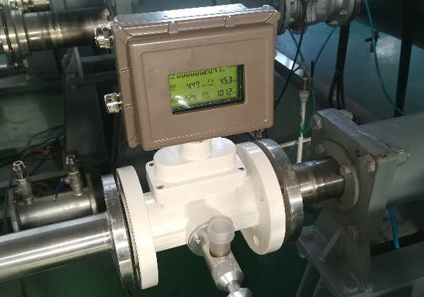
B | Dual power supply, LCD display: no output when 3.6V lithium battery power supply, output three wire pulsewhen DC 24 V power supply
|
C | 4~20mASingle power supply, LCD display: DC24 V power supply, output two-wire system 4 ~ 20mA
|
D | Single power supply, LCD display: DC24 V power supply, output 4~ 20mA + RS485 communication
|
CH | Single power supply, LCD display: DC24V power supply, output 4-20mA+HART protocol |
Advantages and Disadvantages of Different Output Signal Methods for Turbine Flow Meters
Pulse Signal Output
Pulse signal output represents the most fundamental and widely applied signal method for turbine flow meters. The core principle involves capturing the rotational pulses of the impeller using sensors. The number of these pulses is directly related to how fast the liquid is going through, showing any changes in the flow as they happen.
Advantages:
1. It’s really accurate and doesn’t get easily interfered with. Pulse signals are relatively unaffected by factors such as temperature, humidity or changes in voltage, meaning flow data can be relayed accurately. They are useful in circumstances that require very precise measurements, such as in business and trade.
2. It’s got a longer transmission range without needing any extra signal conversion. You can hook it up straight to counters, PLCs, data loggers and other similar devices, which makes wiring a lot easier and cuts costs.
3. It has a rapid response capability, capturing instantaneous flow variations in real time without any signal lag. This makes it suitable for dynamic flow monitoring scenarios, such as flow regulation during fluid conveyance.
4. High compatibility, adaptable to most industrial control systems without requiring dedicated receivers, offering strong versatility.
Disadvantages:
1. Cannot directly output flow values; requires auxiliary equipment for pulse counting and conversion to obtain instantaneous and cumulative flow rates, making it unsuitable for direct reading.
2. High wiring demands; poor contact or improper grounding may cause pulse loss, affecting measurement accuracy.
3. Unsuitable for low-flow scenarios. At extremely low flow rates, the impeller rotates infrequently, generating weak pulse signals susceptible to interference and data loss.
4-20mA analogue signal output
The 4-20mA analogue signal output is a standard signal format that’s used a lot in industrial automation. It basically takes flow signals and turns them into a 4-20mA current signal, which means you can keep the flow going.
Advantages:
1. Intuitive signal format directly interfaces with digital displays and DCS systems, enabling real-time instantaneous flow rate display without additional conversion for user-friendly operation.
2. It’s pretty immune to interference, so current signals stay unaffected by electromagnetic disturbances during transmission, making it perfect for complex industrial electromagnetic environments, like chemical and metallurgical workshops.
3. Enables long-distance transmission with a maximum range of 1000 metres, reducing cabling costs and meeting extended monitoring requirements in large industrial sites.
4. Supports continuous flow regulation through direct integration with control valves and variable frequency drives for closed-loop flow control, compatible with automated control systems.
Disadvantages:
1. Slightly lower accuracy than pulse signals, with minor errors arising during signal conversion, rendering it unsuitable for high-precision trade settlement scenarios.
2. Inability to transmit cumulative flow data necessitates integration with totalisers or systems for integration calculations, incurring additional equipment costs.
3. It’s slower than pulse signals, so there’s a bit of signal lag, which makes it not great for situations where you need to respond really quickly to changes in flow.
4. Complex commissioning means you have to calibrate the flow ranges yourself, which is 4mA and 20mA. This means higher maintenance costs later on.
RS485 Digital Signal Output
RS485 digital signal output uses a serial communication protocol, like Modbus, to send flow data (like instantaneous flow, cumulative flow and operating parameters) in digital format. This makes it so that different devices on a network can talk to each other.
Advantages:
1. Comprehensive data transmission: It simultaneously conveys instantaneous and cumulative flow, medium temperature, pressure and instrument status without requiring additional sensors.
2. High precision: Digital signals eliminate conversion errors, accurately transmitting raw flow data—ideal for high-accuracy metering and data traceability applications.
3. Robust networking capability: A single bus can connect multiple turbine flowmeters, enabling centralised monitoring and management suitable for large-scale industrial sites.
4. Exceptional interference resistance: Digital signals employ differential transmission, effectively shielding against electromagnetic interference and voltage fluctuations for high transmission stability.
Disadvantages:
1. Higher hardware costs: Requires RS485 converters and host computer software, with wiring and commissioning complexity exceeding pulse or 4-20mA signals.
2. Transmission distance is affected by bus load; connecting too many devices reduces range, necessitating repeaters and incurring additional costs.
3. Demands high operator proficiency, requiring familiarity with Modbus protocol and host computer operation, making maintenance relatively challenging.
4. Moderate response speed, influenced by communication rate, rendering it unsuitable for ultra-high-speed dynamic flow monitoring scenarios.
HART Protocol Signal Output
The HART protocol signal employs a hybrid signalling approach, superimposing digital signals onto a 4-20mA analogue signal. This combines the easy-to-use nature of analogue signals with the full range of digital signals, making it a popular choice for signalling in industrial smart instrumentation.
Advantages:
1. High compatibility, enabling direct replacement of traditional 4-20mA instruments without rewiring. Retains original analogue display and control functions while adding the multi-data transmission capabilities of digital signals.
2. It covers all types of data transmission, like instant and cumulative flow, instrument faults, calibration parameters, and more. It supports remote debugging and calibration, which reduces the on-site maintenance workload.
3. Strong interference resistance, combining the anti-interference advantages of both analogue and digital signals. Suitable for complex industrial environments with high stability.
4. High accuracy. The digital signal component eliminates conversion errors, while the analogue signal component meets standard control requirements, catering to both metering and control scenarios.
Disadvantages:
1. Higher cost, as HART protocol instruments, HART handheld communicators, and host computer software are priced above standard pulse or 4-20mA instruments.
2. Complex commissioning and maintenance, requiring specialised personnel to operate HART handheld communicators for parameter configuration and fault diagnosis, placing high demands on operator skills.
3. Relatively slow transmission rate, with the digital signal component transmitting at speeds lower than RS485, rendering it unsuitable for high-frequency data acquisition scenarios.
Recommendations for Selecting Signal Outputs in Turbine Flow Meters
Transmission Distance and Interference Resistance
Signals may attenuate or suffer electromagnetic interference during long-distance transmission, necessitating trade-offs based on the on-site cabling environment.
Short distances or high interference resistance requirements: Prioritise pulse output. Pulse signals are digital quantities that resist distortion during transmission, requiring consideration only of frequency response and cable capacitance.
Long distances or complex electromagnetic environments: Prioritise 4-20mA analogue output. Particularly the two-wire 4-20mA configuration offers the highest interference resistance, suitable for long-distance transmission in industrial high-voltage environments.
Extremely demanding scenarios: Consider digital communication outputs such as RS485. These not only support extended transmission distances but also enable bidirectional transfer of multiple parameters, including instantaneous flow rate, cumulative totals, and fault information.
Interface for associated display or control equipment
The flow meter’s output must match the input interface of the receiving device downstream; otherwise, a signal converter is required.
PLC systems: If the PLC module is an analogue input card, select 4-20mA output; if it is a high-speed counting module, select pulse output.
Display instruments: Confirm whether the display instrument supports frequency input. If not, select a flow meter with 4-20mA output.
Battery-powered equipment: In remote locations without mains power, flow meters with built-in batteries are typically selected. Their outputs are often pulse or local display to minimise power consumption.
Explosion-proofing and power supply methods
The type of signal output depends on the flow meter’s power supply method. This is particularly important in hazardous areas where there are strict intrinsic safety requirements.
Intrinsically Safe Environments: Prioritise the two-wire 4–20 mA output. This method uses the signal cable to supply power, uses low power and is the simplest way to achieve intrinsic safety.
Three-wire or Four-wire Systems: This is suitable for locations with an AC power supply and offers greater output flexibility (e.g. 4–20 mA, pulse, high/low alarms). However, explosion-proof requirements and wiring costs increase.
Battery-powered with pulse output: Suitable for applications requiring no external power supply but occasional data collection via inspection vehicles.
Intelligent and maintenance requirements
Requiring bidirectional communication: Select outputs with RS485 communication (Modbus, HART protocol). This enables flow data to be retrieved and provides remote access to information about the instrument’s self-diagnostics (e.g. bearing wear and reverse flow alarms), which facilitates preventive maintenance.
Multi-parameter monitoring: Opt for intelligent outputs to obtain temperature- and pressure-compensated flow values via a single signal line, enhancing measurement accuracy.
We’re dedicated to offering our clients a complete flow measurement solution, from selection to application, and from solutions to service. Whatever the complexity of your operations, we’re here to use our expertise to solve your problems, helping your business cut costs, improve efficiency and boost competitiveness. We’re excited to build a long-term, stable partnership with you, where we can both grow and create shared value.