Differential pressure transmitters are core sensing instruments in industrial process control; their measurement accuracy directly impacts process stability and operational safety. Regular, standardised calibration is key to ensuring their precise operation and avoiding measurement errors.
Complex operating conditions can easily lead to issues such as zero drift and span drift in transmitters. Mastering scientific calibration methods and adhering to standardised procedures are central to instrument maintenance and operation. This article will break down the core principles of calibration to help ensure the accuracy and reliability of instruments.
Principle of Operation
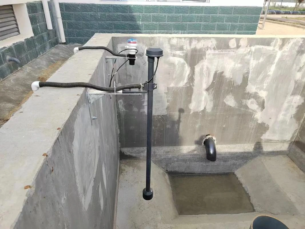
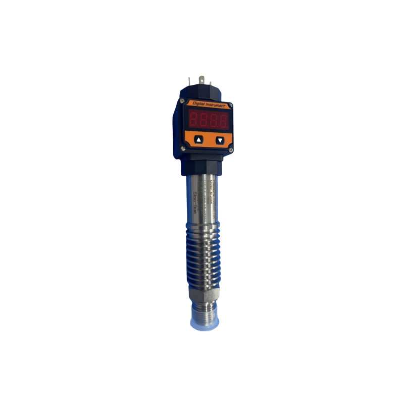
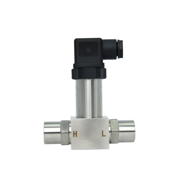
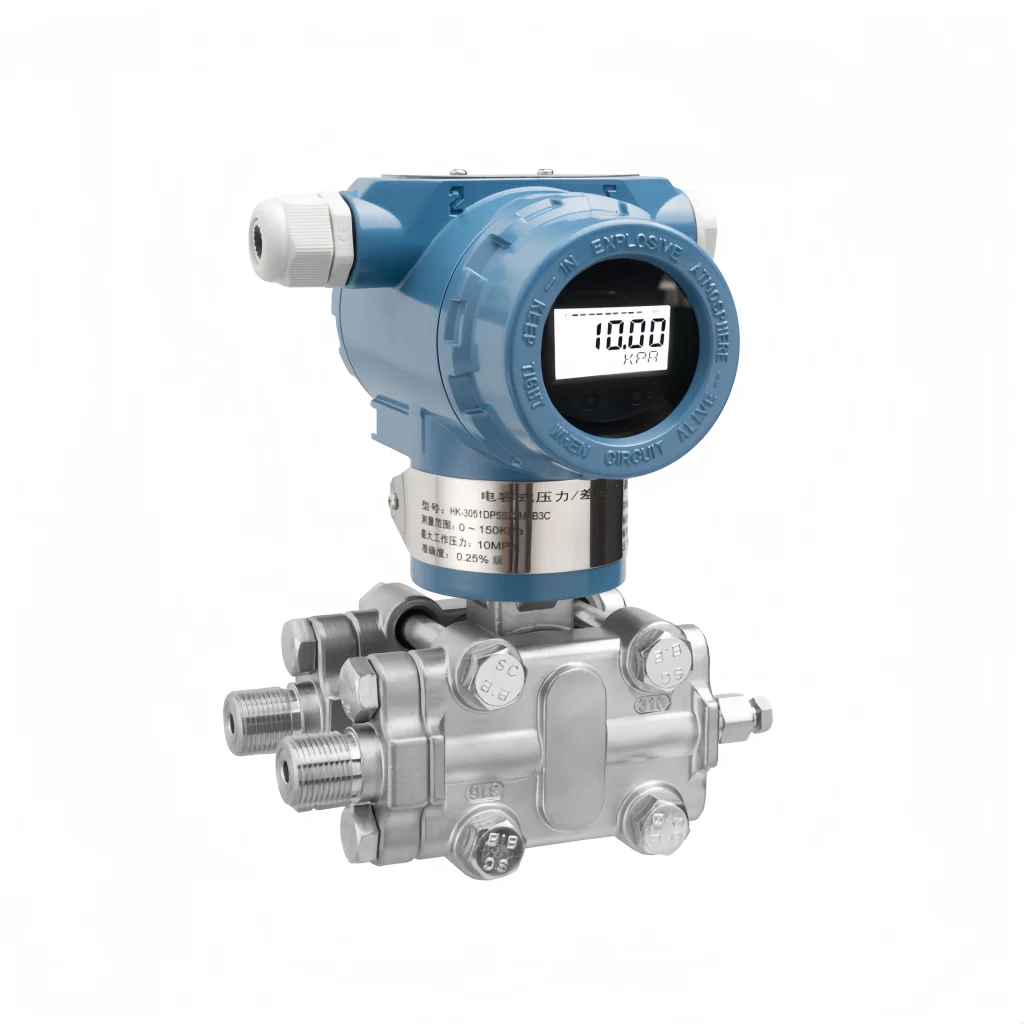
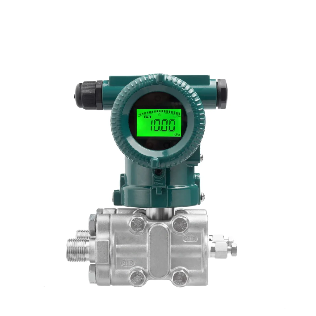
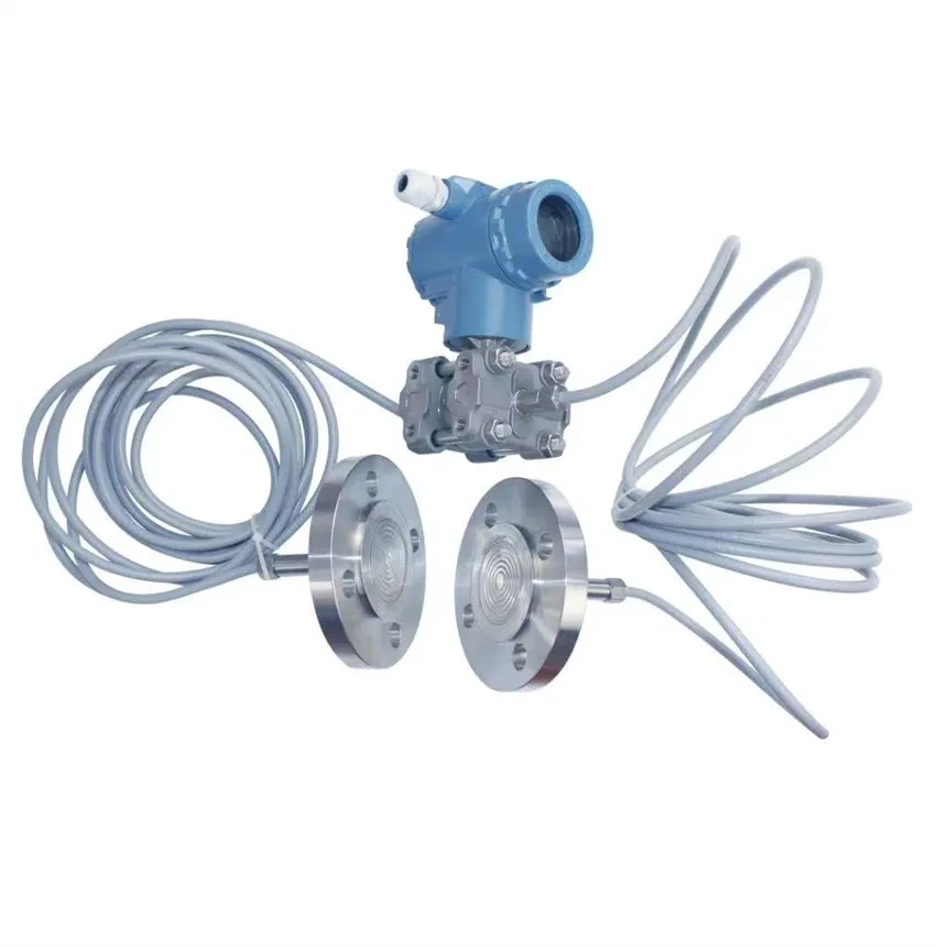
A differential pressure transmitter is a device that measures the pressure difference between the two ends of the transmitter. Unlike standard pressure transmitters, it has two input pressure ports, designated as the positive pressure side and the negative pressure side. Measurement can only be performed when the pressure on the positive pressure side exceeds that on the negative pressure side.
The principle of a differential pressure transmitter is that the isolation diaphragms on both sides of the transmitter’s sensor directly receive the differential pressure from the pressure conduits on either side. This pressure is then transmitted via the sealing fluid within the diaphragms to the measuring element, where the measured differential pressure signal is converted into a corresponding electrical signal. Finally, this signal is transmitted to the converter, amplified and processed, and output as a standard electrical signal.
The Impact of Differential Pressure Transmitter Calibration on Measurements
Impact of an Uncalibrated Zero Point: Zero-point drift can cause a problem where the measurement is always a bit wrong. This is because sometimes the instrument will show a reading that is higher or lower than the actual pressure. This error is particularly pronounced in low-range and low-differential-pressure conditions.
Effects of Uncalibrated Measurement Range: A misaligned measurement range causes linear proportionality errors; the greater the input differential pressure, the greater the error. The instrument’s output is not proportional to the actual operating conditions, resulting in overall distortion of flow and level conversion results.
Effects of poor linearity calibration: The transmitter’s measurement curve is not a straight line, with errors increasing a lot in the mid-range. The high and low pressure points are normal, but the mid-range is inaccurate. This can make it hard to keep an eye on the process and get the measurements right.
Effects of improper offset calibration: Incorrect positive and negative offset settings can cause problems when using negative or static pressure. For example, when measuring the level in a closed tank, the readings may be incorrect. This can make it appear as though there is more or less liquid in the tank than there actually is.
Consequences of uncalibrated static pressure: The diaphragm is subject to off-centre forces due to high-pressure static pressure on the process side, which generates static pressure errors. Over time, measurements slowly change when equipment is used for a long time, which can make the equipment less reliable.
Consequences of uncorrected hysteresis and lag: If the values being measured are not consistent when pressure is rising or falling, and if the instruments are slow to respond, this can cause the control system to become unstable. This can affect automated interlocks and closed-loop control.
Benefits of successful calibration: System errors are eliminated, measurement repeatability and stability are enhanced, and accurate measurement of flow, level and pressure is ensured. This meets compliance requirements for process control, trade metering and safety interlocks, whilst reducing energy consumption and material wastage.
Calibration Procedure
Pre-calibration Preparation
Confirm the calibration environment (the environment must be between 15–25 °C, with a relative humidity of 45–75%, and free from vibration, electromagnetic interference and draughts); Prepare standard equipment with an accuracy 3–5 times higher than that of the instrument to be calibrated, along with standard tools and calibration records; disconnect the transmitter’s piping, power supply and signal lines, release any residual pressure and label the lines; after checking that the instrument’s exterior is free of abnormalities, power it on and allow it to warm up for 15–30 minutes until stable, then proceed to the calibration stage.
Zero Point Calibration
First, apply the zero-point pressure. Slowly adjust the standard differential pressure generator to gradually bring the pressure to 0 kPa (i.e. the transmitter’s zero-point pressure). When you are adjusting it, be very careful not to change the pressure too quickly or too slowly. This will stop the sensor from getting damaged.
After applying the zero-point pressure, allow the instrument to stand for 3–5 minutes until the output signal has fully stabilised, then proceed with deviation adjustment and recording. Observe the reading on the standard ammeter; if the reading deviates from the standard zero-point of 4 mA, fine-tune the instrument using either the built-in mechanical adjustment knob or a dedicated handheld communicator, depending on the transmitter’s adjustment method. Monitor the standard ammeter reading in real time during fine-tuning, and repeat the adjustment until the output signal stabilises within the range of 4 mA ± the permissible deviation.
Span Calibration
Span calibration must be performed after successful zero calibration to ensure the correct calibration sequence and avoid affecting the calibration results. Before calibration, verify that the following prerequisites are met: the span of the standard differential pressure generator must fully cover the rated span of the transmitter under test, and its accuracy must be 3–5 times higher than that of the instrument. Additionally, check that the connection between the standard equipment and the transmitter is secure, with no looseness or leakage.
During the full-scale calibration phase, slowly adjust the standard differential pressure generator to gradually apply the rated differential pressure range of the transmitter under test. The application must be uniform and gradual. Once the instrument’s output signal has stabilised, observe the reading on the standard ammeter. If the reading deviates from the full-scale reference of 20 mA, promptly perform a fine adjustment of the range via mechanical adjustment or a handheld communicator until the output signal stabilises within the range of 20 mA ± the permissible deviation, and record the range data at this point.
Reverse-range calibration is a key part of range calibration, used to check the transmitter’s round-trip accuracy. Then, gradually reduce the differential pressure from full scale to 0 kPa, making sure the rate is consistent throughout. Finally, check that the instrument’s output signal accurately returns to the 4 mA zero point. If there is any deviation, simply repeat the zero-point and full-scale calibration steps until the transmitter’s round-trip accuracy meets the relevant standard requirements. Ensure that the instrument measures accurately across the entire measurement range.
Linearity Calibration
Linearity and hysteresis calibration is used to check that the transmitter is linear across its full measurement range. This makes sure that the accuracy at each measurement point meets the required standards. First, determine the calibration points: There’s zero, 25%, 50%, 75% and full scale. So, based on the rated range of the transmitter we’re testing here, just calculate the differential pressure value for each calibration point, and record these on the calibration chart in advance. This will make it easier to check during the calibration process.
When performing point-by-point calibration, first apply the corresponding differential pressure to the transmitter in the sequence ‘zero point – 25% – 50% – 75% – full scale’. After applying pressure at each calibration point, allow the instrument to stand for 2–3 minutes until the output signal stabilises.
Accurately record the actual differential pressure value displayed by the standard differential pressure generator and the instrument output current value displayed by the standard ammeter; Subsequently, perform reverse-range calibration in the order of “Full Scale – 75% – 50% – 25% – Zero”, repeating the above procedure and recording the relevant data at each point to ensure that both forward and reverse measurement data for each calibration point are complete, for subsequent linearity calculation and analysis.
Additional Calibration
Depending on the transmitter’s actual operating environment and requirements, extra calibrations for static pressure and temperature effects may be performed to make sure the instrument maintains accurate measurements under complex operating conditions.
For static pressure calibration, apply the rated static pressure simultaneously to the transmitter’s positive and negative pressure ports to maintain a differential pressure of 0 kPa. After letting the system stabilise for a bit, check if the instrument’s output signal is different from the 4 mA zero point. If there’s a deviation, check whether it’s within the allowed range. This helps to make sure that changes in static pressure don’t affect the instrument’s accuracy.
To calibrate for temperature effects, simply place the transmitter in high and low-temperature test environments to simulate the temperature variations that might be encountered during normal use. If the temperature changes, redo the zero-point and span calibration steps. Record the calibration data at each temperature and ensure that the impact of temperature changes on the instrument’s measurement accuracy remains within acceptable limits. This will ensure the instrument is stable at different temperatures.
Resetting after calibration
Once you’ve finished calibrating, disconnect the standard equipment from the transmitter, reconnect the transmitter to the process piping, and tighten the pressure taps and seals to make sure there are no leaks. Just reconnect the transmitter’s power supply and signal lines, and power on the unit. But before you do that, make sure the wiring labels are correct.
Practical Applications of Differential Pressure Transmitters
1. Petrochemical Industry
Tank level monitoring: You can measure the pressure difference between the liquid in the tank and the air pressure outside it to calculate the height of the liquid. This means you can keep an eye on and control the tank’s liquid level in real time.
Pipeline flow monitoring: In petrochemical pipelines, differential pressure transmitters can be used to measure the flow rate of the fluid. The fluid flow rate can be calculated by measuring the pressure difference at each end of the pipeline and taking into account factors such as the fluid’s density and the cross-sectional area of the pipeline.
2. Pharmaceutical Sector
Pressure and Level Control in Reactors: In pharmaceutical processes, the pressure and liquid level inside reactors are crucial. Differential pressure transmitters can be used to accurately measure the pressure and liquid level inside reactors, enabling precise control of the reaction process.
3. Power Systems
Steam flow and boiler water level monitoring: In power systems, differential pressure transmitters can be used to monitor the flow of steam or gas in turbines, as well as the level of water in boilers. These measurements are crucial for ensuring the safe and reliable operation of power systems.
4. Water Treatment
Flow and level monitoring: When it comes to water treatment systems, differential pressure transmitters can be used to measure the flow rate and level of fluids in pipelines. Monitoring these factors enables us to control the water treatment process precisely, ensuring the water always meets the required standard.
5. Gas Analysis
Monitoring gas composition and pressure changes in boilers or burners: Differential pressure transmitters can be used to monitor gas composition and pressure changes in boilers or burners. This helps you to control the combustion process and the flow rate. The flow rate can be calculated by measuring the pressure difference in the gas, enabling precise control of the combustion process.
FAQ
When using a differential pressure transmitter for level measurement, is there a difference between installing it on an open vessel and a closed vessel?
There is a clear difference between the two. For open vessels, the positive pressure side of the transmitter is connected to the bottom of the vessel, whilst the negative pressure side is vented directly to atmosphere. The liquid level is calculated using the static pressure difference of the medium, with no additional compensation needed.
When it comes to closed vessels, you need to make sure the negative pressure side is hooked up to the vapour space at the top of the vessel. This helps to balance out the vapour pressure and keeps it from messing with the accuracy of the level reading. If the vapour is corrosive, a isolation tank must be used.
How should differential pressure transmitters be selected and used for corrosive or viscous media?
Select corrosion-resistant diaphragms (made of Hastelloy or fluoroplastic materials). If you’re dealing with viscous media, you’ll need a separation tank and a condensation tank. Make sure you regularly purge the pressure-conducting tubes to get rid of any leftover liquid and crystallised material, so you don’t end up with any blockages.
Before calibration, clean the positive and negative pressure chambers with an inert gas or the corresponding cleaning medium to prevent residual media from affecting calibration accuracy. During installation, minimise the length of the pressure-conducting tubes to reduce media stagnation.
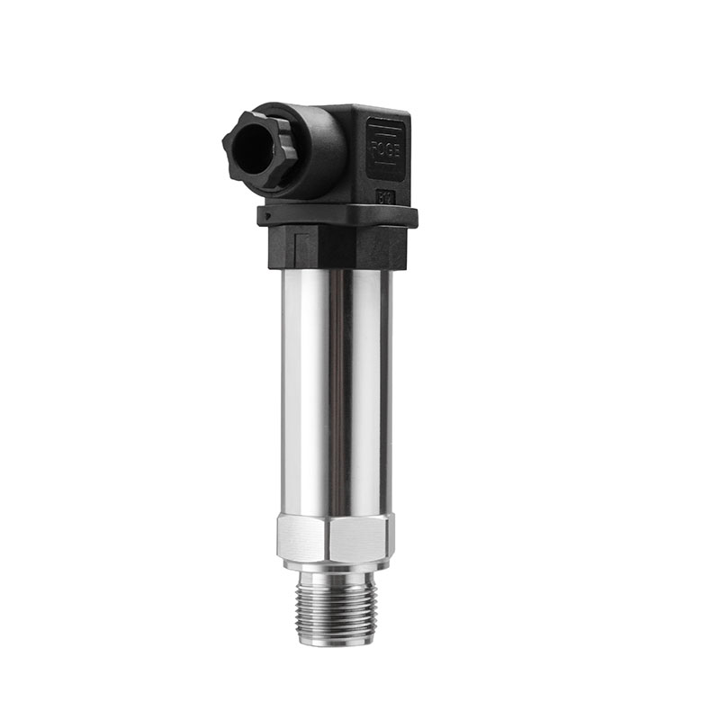
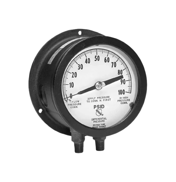
What is the difference between a differential pressure transmitter and a pressure transmitter?
The key distinction lies in the measurement range. A differential pressure transmitter measures the difference between two pressure points, and it can measure gauge pressure or differential pressure. It’s more accurate and it’s good for measuring small pressure differences.
In contrast, a pressure transmitter can only measure the gauge pressure or absolute pressure at a single point; it has a wider measurement range and a relatively simpler structure.
With a long history in the industrial automation sector, Sino-Inst is dedicated to achieving precision and practicality in instrument calibration. We have lots of experience in this field and can provide all the support you need, whether you need advice, technical help or maintenance. We work with clients in many different sectors, like petrochemicals, pharmaceuticals, power generation and water treatment.
We help businesses to control their instruments more effectively and streamline their processes. In the future, we will continue to share our knowledge of industrial instrumentation and promote the importance of proper calibration. Through collaboration with industry partners, we seek to enhance manufacturing processes by taking precise measurements and developing more automated industrial machinery.