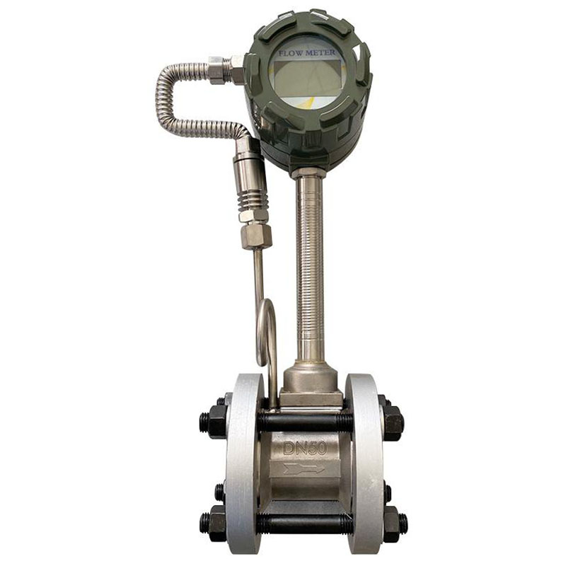
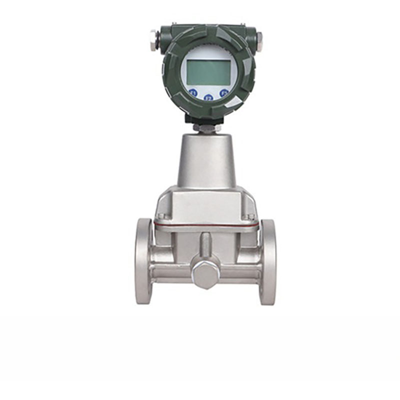
Vortex air flow meters are high-precision instruments that are utilised for the measurement of the flow of gaseous media, including compressed air and atmospheric air. The underlying principle is that of Karman vortex street fluid oscillation, a technique that has been found to be suitable for measuring different types of flow in various industrial applications, including air conveyance, process gas supply and energy efficiency monitoring. It has no moving parts, can resist interference, and has a wide turndown ratio. This makes it a popular choice for industrial air metering. It is used in many industries, such as mechanical engineering, chemical processing, power generation, and building HVAC systems.
Working Principle of Vortex Flow Meters
Vortex flow meters work on something called the Karman vortex street principle. When liquid passes through the meter’s pipeline, it creates vortex structures within the device. The core component is an obstruction (called a vortex generator) installed within the pipeline. When liquid flows past something that’s in the way, it creates these swirly patterns because the speed of the flow changes. The frequency of these vortices is directly proportional to the flow velocity; higher velocities produce vortices at a higher frequency. This vortex frequency is detected by a sensor and converted into a corresponding flow signal, thereby enabling precise measurement of the flow rate.
Air
Atmospheric Air
Pressure Definition: Pressure approximating atmospheric pressure (≤0.1MPa, gauge pressure), without artificial compression, pipeline transport without high-pressure requirements
Transport Characteristics: Primarily open or low-pressure closed-pipe transport, relatively stable flow field with minimal pressure fluctuations
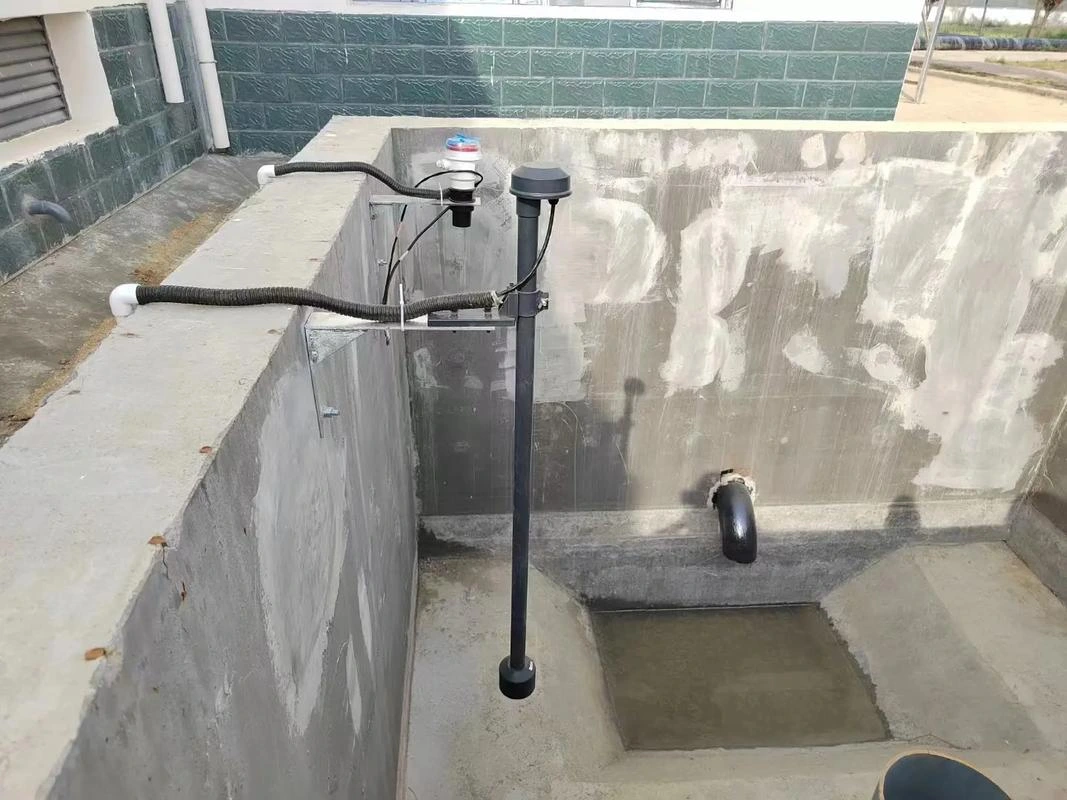
Typical Applications: Factory ventilation, fresh air or exhaust systems for central air conditioning, boiler supply and induced draft fans, process air supply for chemical workshops, exhaust gas treatment blowers
Compressed Air
Pressure Definition: It is compressed with air compressors to a pressure of at least 0.1 MPa. Low-pressure systems (0.1–0.6 MPa) and medium-to-high-pressure systems (0.6–10 MPa) are often used in industry, but some very precise processes need even higher pressures (greater than 10 MPa).
Transport Characteristics: The pipes are high-pressure and closed. The pressure changes based on how much water is being used. Compression makes condensation (which contains tiny drops of liquid), so the liquid has to be dried out and filtered.
Typical Applications: Workshop pneumatic tools Precision machining processes Air compressor station metering Compressed air trade settlement High-pressure pneumatic equipment control.
Special Considerations in Air Measurement
Compressibility Correction: The density of high-pressure air varies significantly with pressure, necessitating dynamic flow correction via temperature-pressure compensation modules. At one air separation plant, failure to compensate for pressure resulted in measurement errors reaching 3% during compressed air monitoring; this was subsequently resolved by enabling the compensation function.
Low Flow Sensitivity: Air’s low density means the signal is weak at low flow rates, so high-sensitivity designs are needed. Measurement errors occurred in the lab because the signals were too weak when low air flow rates were being measured. This issue was resolved by replacing the instrument with a high-frequency vortex flow meter.
Pulsating Flow Handling: Pulsating flow is common in air pipelines (e.g., compressor outlets), necessitating signal fluctuation suppression via damping devices or algorithms. A food processing plant addressed data volatility caused by pulsating flow by installing a buffer tank.
Advantages and Disadvantages of Vortex Flow Meters for Air Measurement
Advantages
Low pressure loss, minimal energy consumption
Thanks to its non-throttling, non-reduced-bore design, it experiences significantly less pressure loss during air passage than orifice plates and differential pressure flowmeters. Long-term use reduces energy consumption in air compressors and fans, making it suitable for continuous air metering applications sensitive to operational costs.
Wide Turndown Ratio and Strong Flow Adaptability
The standard turndown ratios are usually somewhere between 10:1 and 20:1, but some models can go as high as 30:1. It’s accurate even when the flow rate is low, which makes it great for uses where the flow changes a lot or there’s intermittent production (like when compressed air is used in workshops or the ventilation flows in industrial buildings change).
Simple structure, low maintenance costs
Features no vulnerable mechanical moving parts; the main body comprises only a vortex generator and sensor, minimising mechanical failures. Routine maintenance involves merely cleaning dust, oil residues, and other contaminants from the generator surface. Frequent disassembly for calibration is unnecessary, with maintenance frequency significantly lower than orifice plates or turbine-type air flow meters.
Moderate installation requirements with high versatility
Requires only 10D upstream and 5D downstream straight pipe sections, substantially less than orifice plate flowmeters. Typically requires no additional flow straighteners under standard conditions, occupying minimal installation space. Models of the same pipe diameter accommodate various air conditions including atmospheric air and compressed air without customised calculations, offering superior versatility compared to orifice plates.
Stable measurement accuracy with wear resistance
Standard measurement accuracy ranges from ±1.0% to ±1.5%, meeting industrial air metering and energy consumption assessment requirements. The vortex generator is made from hard alloy or stainless steel, which can resist high-speed air erosion. This makes sure that the accuracy doesn’t change a lot over time and that you don’t need to calibrate it as often.
Highly integrated intelligent models for industrial automation
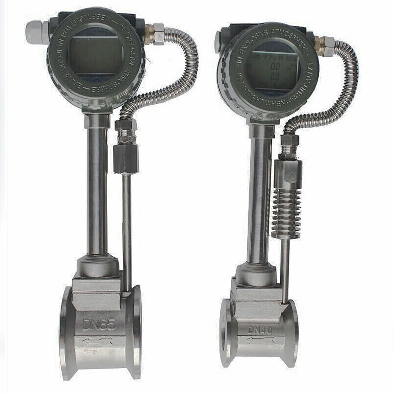
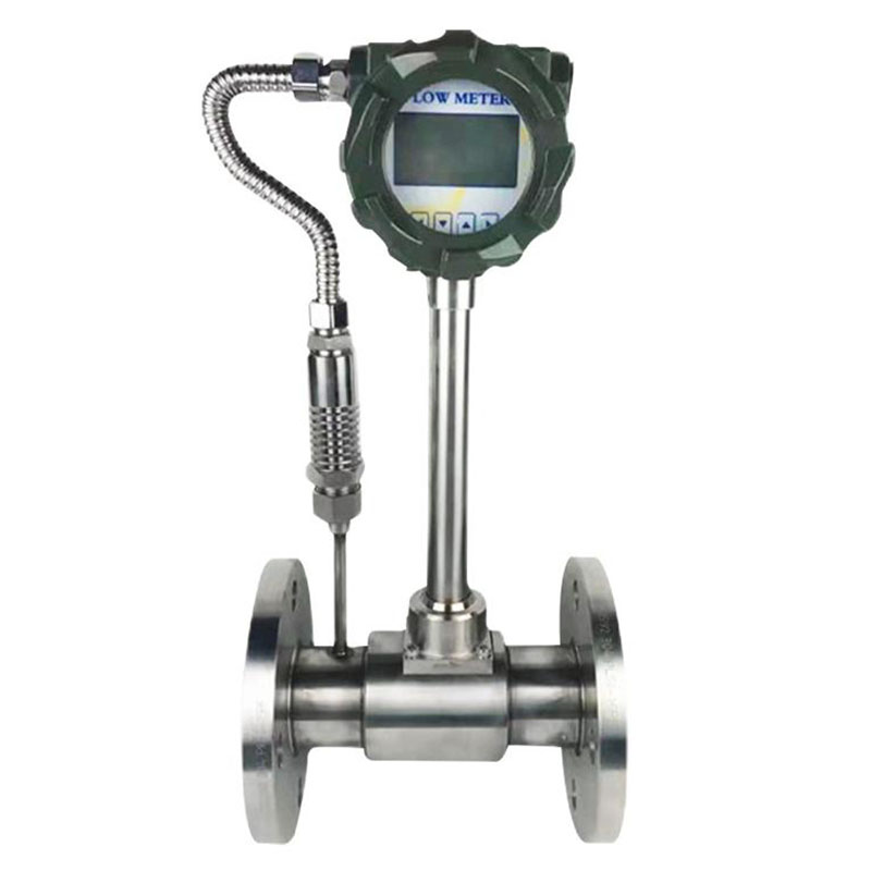
The intelligent integrated vortex flow meter incorporates temperature and pressure compensation, local digital display, and RS485 remote transmission. It directly outputs air flow at standard conditions, eliminating the need for additional display units or transmitters. This facilitates installation and integration with PLC/DCS industrial control systems, aligning with factory air metering automation upgrades.
Broad applicability with comprehensive bore sizes
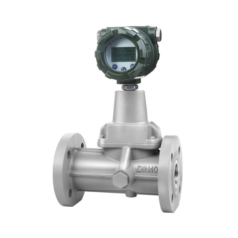
Accurately measures common industrial air media including atmospheric air and compressed air. Full bore size coverage from DN15 to DN300 meets most small-to-medium bore air metering requirements in industrial settings.
Disadvantages
Sensitive to medium conditions
Measures only single-phase clean fluids. If the medium contains solid particles, dust, viscous substances, or exhibits gas-liquid or gas-solid two-phase flow (e.g., steam laden with droplets, liquid containing bubbles, wastewater with solids), it may clog or wear the vortex generator, causing turbulent vortex signals and significantly increasing measurement errors or even signal loss.
Poor vibration resistance; vibrations readily induce measurement drift
The sensor detects flow by measuring micro-vibrations generated by vortex streets. If installed near high-vibration sources such as air compressors, fans, or compressors, external vibrations may superimpose on vortex vibrations, creating false signals. This causes significant fluctuations in instantaneous air flow and inaccurate cumulative flow measurements, necessitating the installation of vibration-damping pads or relocation away from vibration sources.
Accuracy degradation at low flow rates
Subject to minimum flow velocity constraints. When air velocity falls below the threshold, stable vortex generation becomes impossible, causing metering accuracy to plummet. This renders the device unsuitable for industrial applications requiring measurement of ultra-low air flow rates.
Upper limits on temperature and pressure adaptation
Specialised materials and configurations must be customised for extreme conditions like high-temperature, high-pressure compressed air, significantly increasing costs. Moreover, abrupt changes in air temperature and pressure may temporarily destabilise vortex formation, causing fluctuations in flow signals.
Reduced cost-effectiveness for large-diameter air measurement with slight pressure loss increase
Cost-effectiveness is high for small-to-medium diameters (DN15–DN200). However, when pipe diameter ≥ DN300, vortex flow meter manufacturing costs and installation complexity increase substantially. Pressure loss also rises slightly with diameter, making ultrasonic flow meters a more economical and convenient alternative.
Sensitive to localised resistance elements in straight pipe sections
Although straight pipe requirements are lower than for orifice plate flowmeters, installation adjacent to elbows, reducers, valves, or other localised resistance elements without sufficient upstream straight pipe can disrupt the air flow field. This leads to uneven vortex generation, causing measurement errors. Strict adherence to installation specifications is essential.
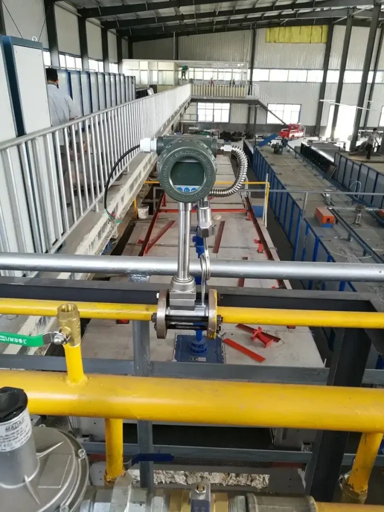
Vortex Flow Meter Installation Guide
1. Medium Parameter Correction:
When measuring media requiring temperature and pressure correction, such as compressed air or steam, pressure tapping points and temperature measurement points must be strictly positioned according to specifications: pressure taps shall be located 3 pipe diameters downstream of the flow meter, while temperature measurement points shall be positioned 5 pipe diameters downstream. This ensures collected parameters accurately reflect the medium state passing through the flow meter, minimising correction errors.
2. Size Matching:
The pipe’s internal diameter must precisely match the sensor’s nominal bore to prevent velocity discontinuities caused by diameter changes, which could introduce measurement errors. Additionally, the internal diameters of gaskets on both sides of the sensor must strictly correspond to the sensor’s nominal bore. This prevents fluid turbulence from undersized gaskets or leakage from oversized gaskets.
3. Sensor Protection:
To prevent any damage during installation, it’s important to take steps to protect it. This is to stop it from being damaged by things like collisions or being dropped, or by being exposed to high temperatures for a long time. Where there is a risk of liquid deposition, sensors can be installed with a vertical tilt of up to 30°, as long as this doesn’t affect the accuracy of the measurements.
4. Flow Direction Verification:
Before you install it, check the arrow on the sensor housing to make sure it is pointing in the right direction for the fluid to flow.
FAQ
Can vortex flow meters be installed vertically?
Vertical installation is permissible, provided the core requirement is met: the air medium must flow from bottom to top. This prevents gravitational settling of the medium from creating localised turbulence that disrupts stable vortex generation. Additionally, the installation locati0n must be free from liquid accumulation and impurity deposits.
Calibration Methods for Vortex Flow Meters
1. Static Calibration Method: This method is suitable for low flow rates. First, install the vortex flow meter alongside a standard flow meter on the same pipeline. Then, compare the measurement results from both meters to calculate the deviation and accuracy of the vortex flow meter.
2. Dynamic Calibration Method:This method is suitable for high flow rates. First, supply fluid to both the vortex flow meter and the standard flow meter via a stable flow pump. Then, compare the measurement results from both meters to calculate the deviation and accuracy of the vortex flow meter.
3. Online Calibration Method: This approach is suitable for scenarios demanding high real-time requirements. The vortex flow meter and a standard flow meter are simultaneously installed on the pipeline and connected to a central control system. Real-time monitoring and comparison of both meters via the central control system enables online calibration.
Key Differences Between Mass Flow Meters and Vortex Flow Meters
How it’s measured: Mass flow meters measure the amount of a fluid flowing directly. Vortex flow meters measure the flow rate of a fluid by looking at how often a vortex is created. The first one is more about controlling the masses, while the second one is more about the amount of stuff going through.
Suitable Applications: Mass flow meters are ideal for scenarios demanding precise mass flow measurement, particularly for high-accuracy measurement of liquid and gas flows. Vortex flow meters are suitable for medium-flow gas, liquid, and steam measurement, demonstrating particular advantages under relatively stable temperature and pressure conditions.
Accuracy and Stability: Mass flow meters offer higher accuracy and maintain good stability across varying fluid characteristics, though they are comparatively more expensive. Vortex flow meters provide moderate accuracy suitable for most industrial applications and are relatively economical in price.
When it comes to industrial settings where precision and efficiency are key, picking the right flow meter isn’t just about choosing a measuring instrument. It’s about choosing a reliable partner that you can depend on in the long term. Sion-Inst has lots of experience in measuring the flow of liquids in industry. The company’s main focus is on developing and implementing solutions for measuring flow in different situations.
Our comprehensive range of standardised flow meters enables tailored selection based on your specific site requirements—be it atmospheric or high pressure, flow range, or installation environment. We complement this with professional on-site installation guidance, commissioning and calibration, alongside comprehensive operational maintenance support. From equipment selection to sustained operation, ensuring your precise measurement needs are safeguarded throughout the entire process.