In diverse fluid measurement scenarios across industrial production, the precise control of flow parameters directly impacts both production efficiency and product quality. The insertion vortex flow meter, with its core advantages of straightforward installation and broad compatibility, has become the preferred solution for numerous enterprises seeking to resolve flow measurement challenges.
Working Principle of Insertion Vortex Flow Meters
The core measurement logic of insertion vortex flow meters is based on the classical Karman vortex street fluid dynamics principle, combined with an insertion-type structural design. This setup can be adjusted to meet the fluid measurement needs of both non-full-bore and full-bore flow in large-diameter pipelines. It doesn’t have any mechanical moving parts. Instead, it uses the fluid’s natural flow properties to make precise measurements. The Karman vortex street principle is a theory that explains how regular vortices form on either side of a non-streamlined object when fluid flows past it at a certain speed. These swirling masses of air move at a set speed within the fluid, creating a pattern of swirling air known as a Karman vortex street. By measuring the frequency of these oscillations, the fluid velocity can be calculated, thereby enabling flow measurement.
The operational mechanism is as follows:
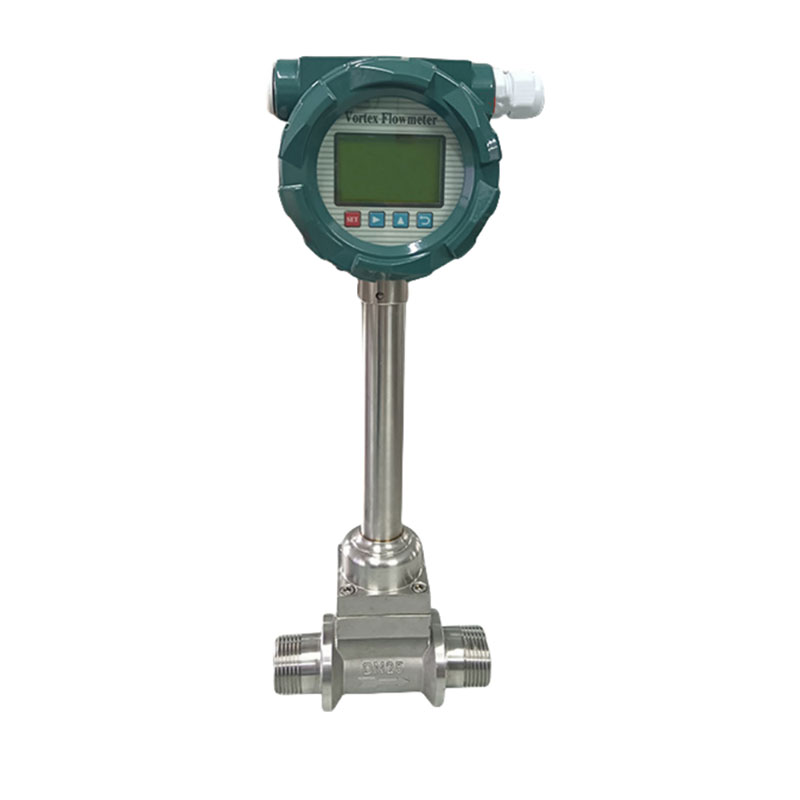
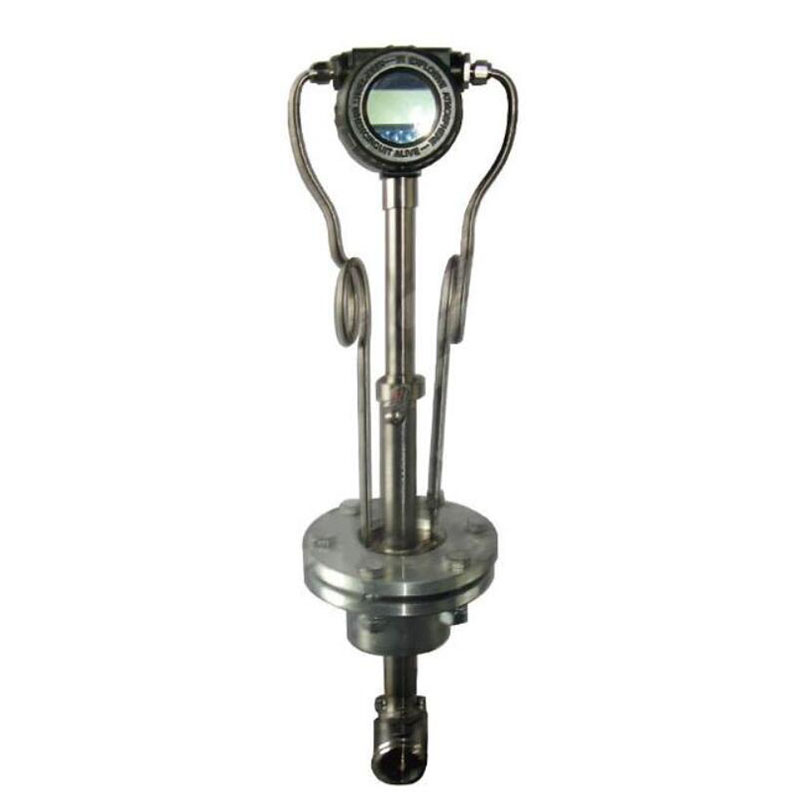
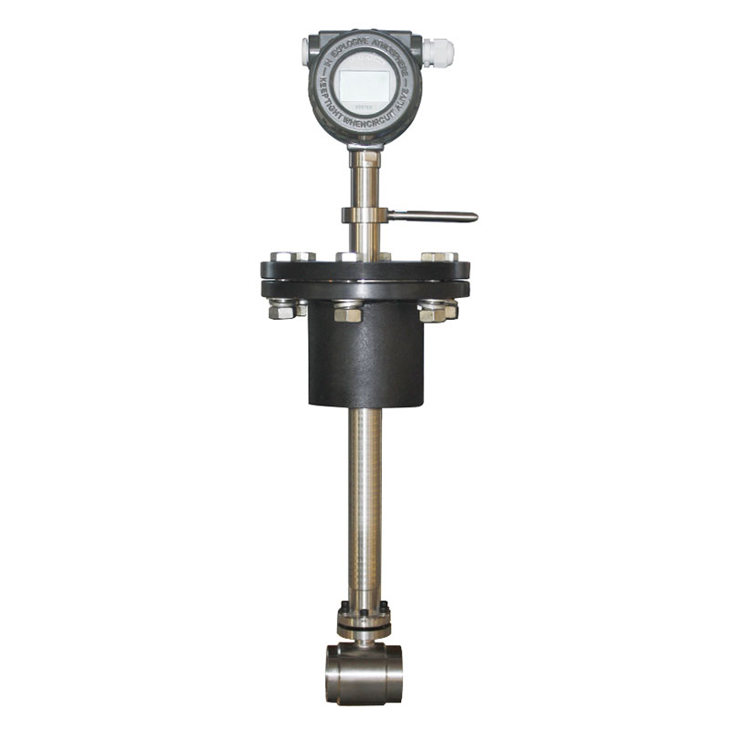
1. Flowmeter Probe: The primary component is a probe fitted with a vortex generator. When liquid flows past the vortex generator, it creates swirly patterns called vortices on either side, forming a series of them. People call this a “Karman vortex street.”
2. Sensor Detection:The probe sensors detect Karman vortex street fluctuations. Many of these devices transform vibrations into electrical impulses using thermosensitive, piezoelectric, or electromagnetic principles.
3. Signal Processing: The electrical signal is first amplified, filtered and shaped before being transmitted to the flow calculator. The flow calculator processes this signal to determine the fluid velocity and flow rate, subsequently displaying and outputting the results.

Advantages and Disadvantages of Insertion Vortex Flow Meters
Advantages
Convenient installation with low retrofitting costs
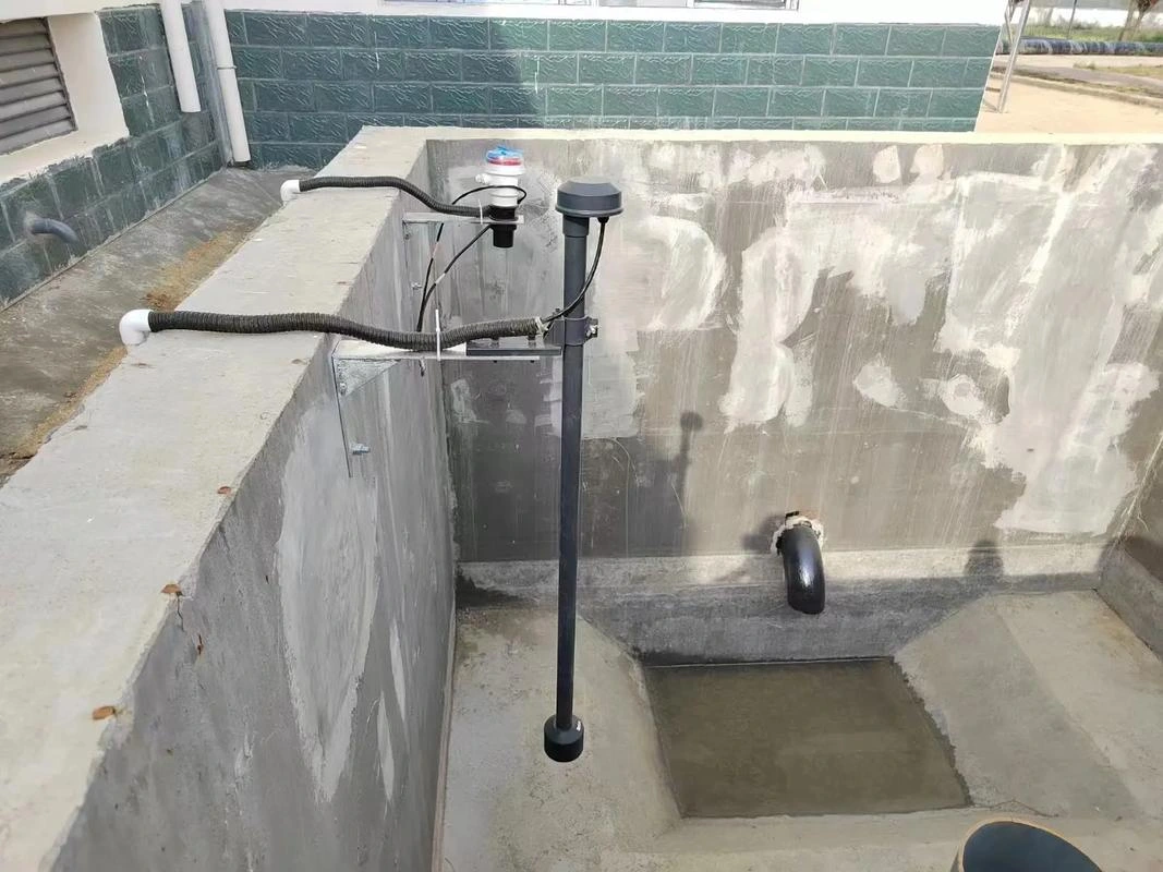
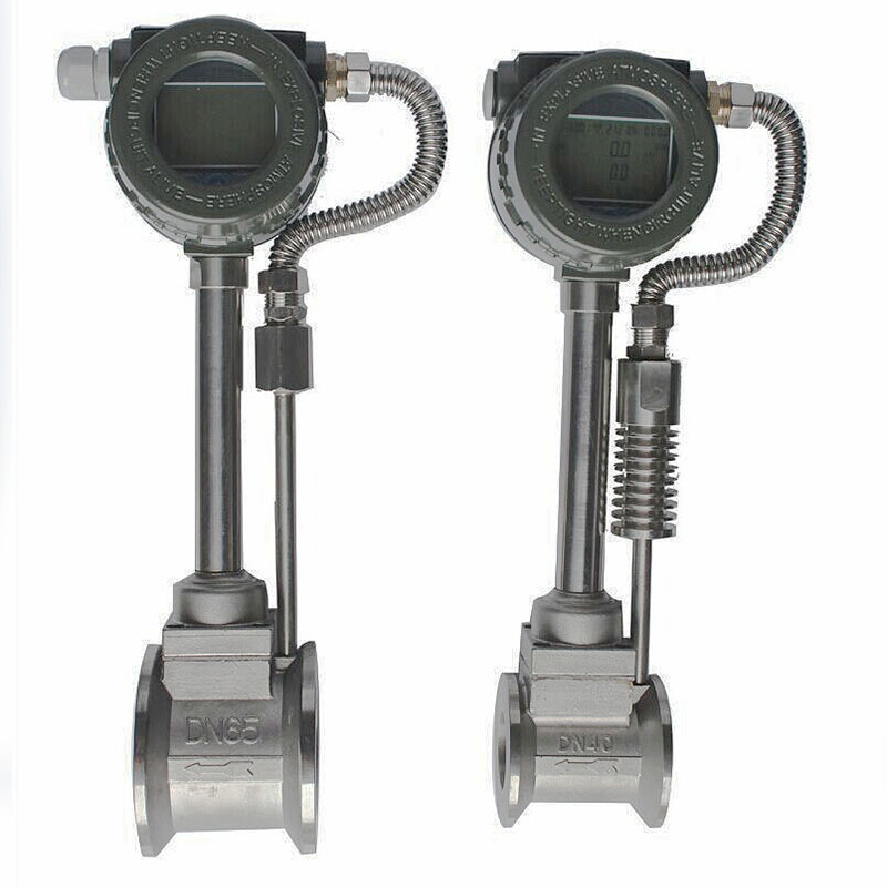
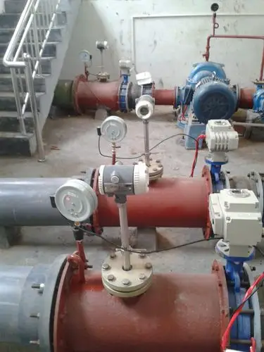
There is no need to cut or replace entire large-diameter pipelines. The probe is inserted into the central flow zone after an opening has been drilled in the pipe wall. This results in a short construction period and minimal disruption to on-site production, making the method particularly suitable for retrofitting flow measurement systems to operational pipelines. It significantly reduces pipeline modification costs.
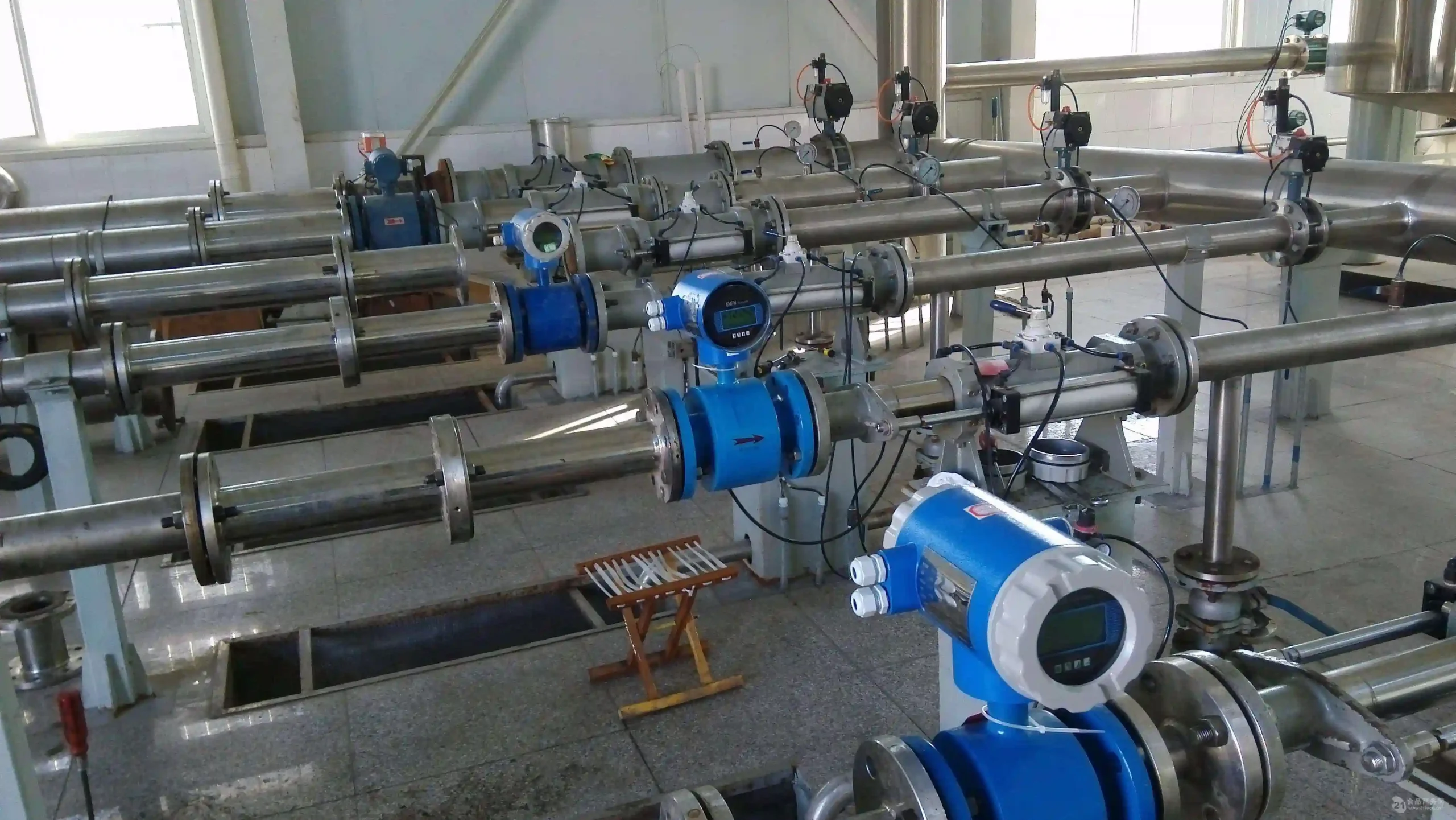
Suitable for large-diameter pipelines with broad measurement range
Designed for large-diameter pipelines, it can handle various fluid media, including liquids, gases, and steam. With a wide turndown ratio, it can adapt to minor fluctuations in industrial fluid velocities. It meets the metering requirements of large-diameter pipelines in multiple sectors, including chemical processing, power generation, and municipal water supply and drainage.
No Wear-Prone Moving Parts, Extended Service Life
The measurement process involves no mechanical rotation or friction components, relying solely on the interaction between the fluid and the vortex generator to achieve measurement. This minimises the risk of component wear and jamming. Under stable operating conditions, the equipment exhibits low failure rates and a longer service life.
Simple maintenance, low operational costs
Its straightforward structure features highly integrated core probes and sensors. Routine maintenance requires only periodic checks of probe cleanliness and wiring connections, eliminating complex disassembly for calibration. Certain models support hot-swappable probes, enabling maintenance and calibration without shutdown, further reducing operational and maintenance time and labour costs.
Stable measurement accuracy with robust interference resistance
Vortex frequency exhibits a strict linear relationship with fluid velocity. Measurement precision is minimally affected by fluid properties (e.g., viscosity, particularly in low-viscosity media). The transmitter unit filters and shapes raw signals, effectively eliminating minor electromagnetic interference on-site to ensure stable and accurate flow data.
Disadvantages
Requirements for fluid velocity and pipeline conditions
The fluid within the pipeline must be in a fully developed turbulent state, necessitating sufficient straight pipe sections upstream and downstream. If there are not enough straight pipe sections, the speed distribution can be uneven, which can make the measurement inaccurate. Also, the system performs poorly with low-velocity media, meaning it has a lower measurement limit and is unsuitable for measuring micro-velocity fluids.
Susceptible to mechanical vibration interference
Vortex detection sensors are sensitive to vibration signals. If high-power pumps, fans, or other vibration sources are present at the installation site without effective vibration damping measures, vibration signals may be erroneously captured by the sensor. These signals can superimpose on vortex signals, causing signal distortion and compromising flow data accuracy.
Certain requirements for medium cleanliness
If the measured medium contains substantial solid particles or fibrous impurities, these may adhere to the vortex generator and sensor probe. This not only alters the generator’s shape, disrupting the regularity of vortex generation, but may also obstruct the sensor detection channel, causing signal loss. In severe cases, it can wear down the generator, reducing measurement accuracy.
Not suitable for high-viscosity media or those with high lower Reynolds number limits
For highly viscous liquid media (such as heavy oil or viscous chemical feedstocks), laminar flow tends to form around the vortex generator, making it difficult to generate stable Karman vortices. This significantly reduces measurement accuracy and may even prevent normal metering.
Applications of Insertion Vortex Flow Meters
Energy Sector
Within the energy sector, insertion vortex flow meters are extensively employed for measuring the flow of gases such as natural gas and steam, as well as liquids. These flow meters can handle the tough operating conditions often found in the energy industry thanks to their high pressure and temperature resistance, so you can be sure they’ll keep going for a long time.
Chemical Industry
In chemical production, it’s really important to measure the flow of liquids precisely to keep control of the product and how the reactions are going. Insertion vortex flow meters can measure the flow of stuff like chemicals, solvents and gases. They’re really adaptable, which means they can meet the strict requirements of chemical processes.
Environmental Protection Sector
In the field of environmental protection, insertion vortex flowmeters are widely used in wastewater treatment, sludge dewatering and gas emission monitoring processes. These meters measure water and gas flow rates with great precision, helping environmental enterprises to monitor emissions more effectively and ensure compliance with environmental regulations.
Food and Beverage Industry
Insertion vortex flow meters are also very important in the food and drink industry. They can measure the volume of liquids such as water, drinks and fruit juice very accurately. These instruments don’t touch the fluid, so they don’t create contaminants. This means they meet the strict cleanliness and precision rules of the food industry.
Selection Guide for Insertion Vortex Flow Meters
1. Fluid Type and Characteristic Compatibility
Gas/Steam Applications: Consider the impact of temperature and pressure on density, enhancing accuracy through temperature-pressure compensation. For example, superheated steam needs to measure both temperature and pressure at the same time. The actual flow is calculated using a formula.
Liquid Applications: Make sure there are no bubbles or other impurities that could disrupt the signals from the Vortices. You should definitely use this with degassing devices or filters. If you’re dealing with liquids that have particles in them, you should go for larger vortex generators to reduce the risk of clogging.
Corrosive Media Handling: Select vortex generator materials matching the medium’s properties. 316L stainless steel suits general media, while Hastelloy C-276 or tantalum are recommended for highly corrosive applications (e.g., chlorine gas, concentrated sulphuric acid).
2. Flow Rate and Nominal Diameter Parameters
Flow Range Design: The design flow rate must cover actual operating conditions with a 10%-20% margin. For instance, a steam pipeline with a design flow rate of 50 t/h should employ a flowmeter with a range of 0-60 t/h.
Flow Velocity Control: Gas velocities should be maintained between 5 and 60 m/s, and liquid velocities between 1 and 10 m/s. Excessively low velocities should be avoided as these cause signal instability, while excessively high velocities increase pressure loss and can damage the probe.
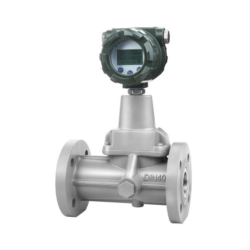
Nominal diameter matching principle: In order to prevent measurement errors caused by throttling or enlargement, the nominal diameter of the flow meter must match that of the pipeline. Reduced/enlarged diameter designs require velocity verification.
3. Accuracy and Stability Parameters
Accuracy Class Selection: High-accuracy scenarios (e.g., trade settlement, energy auditing) require ±1.0% FS (full scale) accuracy; General-purpose applications (e.g., process control) may utilise ±1.5%FS accuracy;low-cost scenarios (e.g., environmental monitoring) may employ ±2.0%FS models.
Long-term stability assurance: High-quality vortex flowmeters should exhibit repeatability ≤0.5%FS to ensure sustained measurement stability;Linearity must remain ≤1.0%FS across 10%-100% of the measurement range to mitigate non-linearity errors.
4. Environmental Adaptability Parameters
Temperature Range Compatibility: Sensor temperature range must cover actual operating conditions. Standard models support -40°C to 400°C, while high-temperature models (requiring cooling units) extend to -70°C to 500°C. Transmitter ambient temperature must be controlled within -20°C to 60°C (standard) or -40°C to 85°C (wide-temperature).
Pressure Rating Compatibility: Standard models support 0-2.5MPa (flanged/clamp-on type), while high-pressure models (requiring special design) cover 0-10MPa scenarios. Special applications (e.g., deep-sea pipelines) necessitate verification of the flowmeter’s pressure resistance.
Protection Rating Requirements: IP65 suffices for dry indoor environments, whereas outdoor or high-humidity scenarios demand IP67/IP68 to prevent ingress of rainwater or condensation.
5. Signal Output and Communication Parameters
Analogue Output Type: 4-20mA signal offers strong anti-interference capability, suitable for long-distance transmission to PLC or DCS systems; pulse output (frequency range 1-1000Hz) is applicable for flow accumulation or batch control.
Digital Output Protocol: RS485/Modbus protocol facilitates integration into IoT platforms, supporting remote monitoring and data upload; wireless transmission (LoRa/NB-IoT) is suitable for pipeline monitoring in remote areas, reducing cabling costs; protocol compatibility must cover industrial protocols such as HART and Profibus to meet diverse system integration requirements.
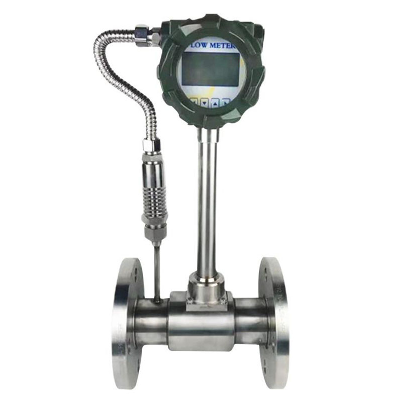
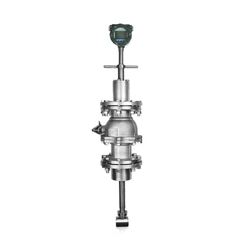
6. Installation and Maintenance Parameters
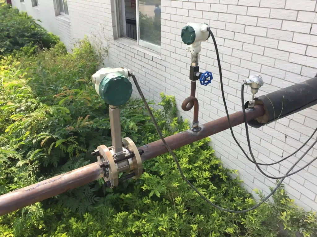
Installation Orientation Specifications: For horizontal installation, the vortex generator arrow must align with fluid flow direction. Requires minimum 10D upstream straight pipe section and 5D downstream straight pipe section. Vertical installation is suitable for scenarios requiring prevention of bubble or impurity deposition (e.g., liquid measurement).
Grounding and Explosion-Proof Design: Metal pipelines need to be properly grounded (with a grounding wire diameter of at least 5.5 mm²) to prevent safety issues caused by static electricity build-up. For explosion-proof applications such as chemical production lines, opt for flow meters with an Ex d IIC T6 rating.
Maintenance Interval Recommendations: Regular calibration (every 1-2 years) and cleaning (every 3-6 months for vortex generators and pipe interior walls) are critical for maintaining accuracy.Metal components require annual corrosion inspection with replacement as necessary.
It’s really important to choose the right stuff to get the most out of insertion vortex flowmeters. If you match the measurement range, material, structure, and extra functions to the on-site medium, pipeline parameters, and operating conditions, you can get the most out of their metrological value while avoiding measurement inaccuracies and equipment wear caused by improper selection.
Sion-Inst focuses on large-diameter pipeline metering requirements across industries. Integrating premium product resources with specialised technical expertise, we swiftly deliver precise selection recommendations tailored to your operational conditions. We provide cost-effective, highly compatible insertion vortex flow meters alongside comprehensive solutions, empowering enterprises to achieve standardised, efficient, and low-cost flow measurement. We look forward to collaborating with you, leveraging professional metrology to drive production upgrades.